Page 112 of 258

111GETTING THE BEST OUT OF YOUR VEHICLE
SELECTING AUTOMATIC/
SEQUENTIAL MANUAL
OPERATION
The main feature of this gearbox is
the possibility of being used in the au-
tomatic or sequential manual mode.
The operating mode is chosen posi-
tioning the gearshift lever in the right
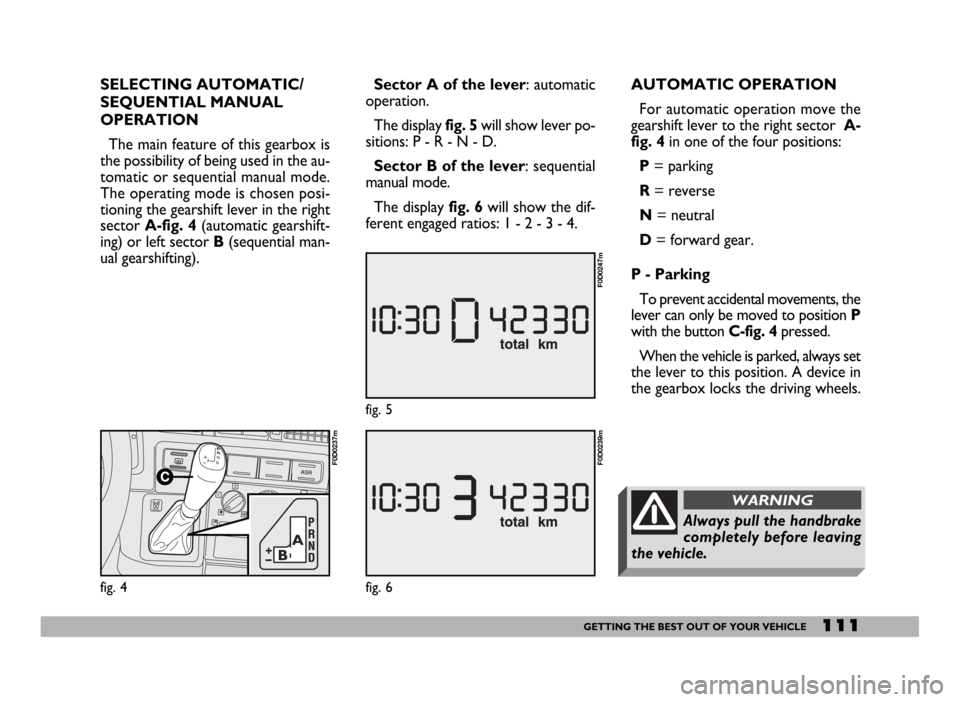
sector A-fig. 4(automatic gearshift-
ing) or left sector B(sequential man-
ual gearshifting).
fig. 4
F0D0237m
Sector A of the lever: automatic
operation.
The display fig. 5will show lever po-
sitions: P - R - N - D.
Sector B of the lever: sequential
manual mode.
The display fig. 6will show the dif-
ferent engaged ratios: 1 - 2 - 3 - 4.AUTOMATIC OPERATION
For automatic operation move the
gearshift lever to the right sector A-
fig. 4in one of the four positions:
P= parking
R= reverse
N= neutral
D= forward gear.
P - Parking
To prevent accidental movements, the
lever can only be moved to position P
with the button C-fig. 4pressed.
When the vehicle is parked, always set
the lever to this position. A device in
the gearbox locks the driving wheels.
fig. 6
F0D0239m
fig. 5
F0D0247m
Always pull the handbrake
completely before leaving
the vehicle.
WARNING
Page 115 of 258

114GETTING THE BEST OUT OF YOUR VEHICLE
SEQUENTIAL MANUAL
OPERATION
For the sequential manual operation
mode, move the lever to the left sec-
tor B-fig. 4with two positions:
(+) = engagement of the higher ra-
tio;
(–) = engagement of the lower ratio.
Moving the gearshift lever to the
manual sector is only possible from
position D: the ratio selected by the
automatic gearbox when the lever is
moved will remain engaged.
When the sequential manual mode is
selected, the display shows the en-
gaged gear fig. 6.
To select the higher ratio move the
lever in the (+) direction and to shift
down move the lever to (–).IMPORTANTIf the request to
downshift would cause engine
overevving, this is eliminated by the
electronic control unit. Moreover, if
the manually engaged gear causes en-
gine overevving, the electronic control
unit will shift gear automatically to the
most appropriate one (AUTO-UP).
When the sequential man-
ual mode has been set and
a high gear is engaged, to acceler-
ate rapidly, for example to over-
take, it is necessary to downshift
by hand: the kickdown feature
cannot be engaged!
WARNING
Engaging the automatic
WINTER programme
(only with lever in “D”)
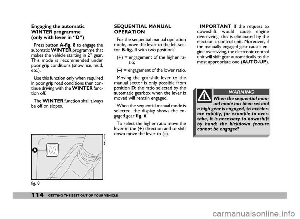
Press button A-fig. 8to engage the
automatic WINTERprogramme that
makes the vehicle starting in 2
ndgear.
This mode is recommended under
poor grip conditions (snow, ice, mud,
etc.).
Use this function only when required
in poor grip road conditions then con-
tinue driving with the WINTERfunc-
tion off.
The WINTERfunction shall always
be off on slopes.
fig. 8
F0D0241m
Page 178 of 258

177VEHICLE MAINTENANCE
ELECTRONIC
CONTROL UNIT
When the vehicle is being used nor-
mally, special measures are not nec-
essary.
The following instructions must be
followed very carefully however, if
you work on the electrical system or
in cases where emergency starting is
necessary:
– never disconnect the battery from
the electric system while the engine is
running;
– disconnect the battery from the
electric system if you are recharging it;
– never perform emergency starting
with a battery charger. Always use an
auxiliary battery;
– be particularly careful when con-
necting the battery to the electric sys-
tem. Make sure that the polarity is
correct and that the connection is ef-
ficient;
– do not connect or disconnect the
terminals of the electronic units while
the ignition key is at MAR;
– do not check polarity through
sparking;– disconnect the electronic control
units if you are electrically welding the
vehicle body. Remove the units if tem-
peratures exceed 80 °C (special op-
erations on the bodywork, etc.).
IMPORTANTIf the sound system
or vehicle alarm systems are not in-
stalled correctly, they can interfere
with the working of the electronic
control units.
Modifications or repairs to
the electrical system car-
ried out incorrectly and without
bearing the features of the system
in mind can cause malfunctions
with the risk of fire.
WARNING
SPEED LIMITER
On certain version, the injection con-
trol unit is set to limit the vehicle
speed at a max. preset limit.
Speed limits are the following:
– for Minibus versions (M2 homolo-
gation category): 100 km/h;
– for good Transport versions (ve-
hicle dead weight: > 3.5 t) (N2 ho-
mologation category): 90 km/h;
Label (fig.16) with admitted top
speed (90 or 100 km/h according to
versions) is applied on the wind-
screen.
This limit has been established by Eu-
ropean Directive 2002/85/EC, what-
ever violation is therefore punishable
by law.
IMPORTANTWhen the device
comes into action, the speed value
displayed on the instrument panel
could be approx. 10% higher than the
actual one.
fig. 16
F0D0299m