Page 33 of 258
32GETTING TO KNOW YOUR VEHICLE
fig. 39
F0D0217m
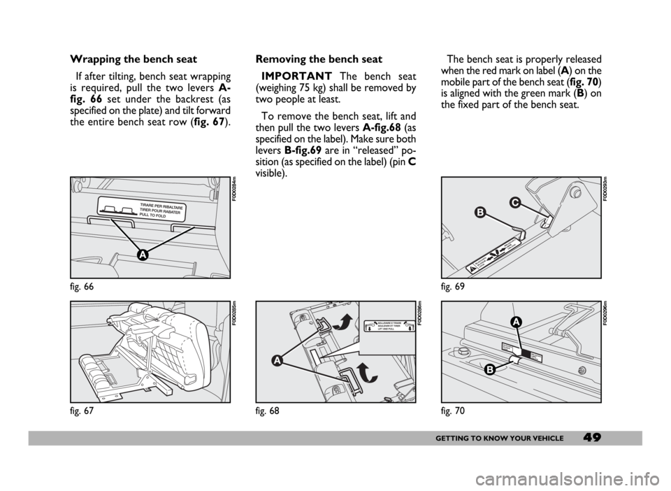
ENGINE OIL LEVEL GAUGE
(where provided)
The gauge graphically displays the en-
gine oil level between the MINand
MAXreference points.
To perform measurement ensure
the vehicle is on a flat ground, then
proceed as follows:
1)when the engine is not running,
turn the ignition key to MAR;
2)the word “OIL” will be displayed
for 5 seconds together with six dashes
and five or six boxes showing the cor-
rect engine oil level;
Fig. 38- Correct oil level.
Fig. 39- Minimum oil level.
Should oil level be at minimum, re-
store oil level to the correct level as
soon as possible. Anyhow, before top-
ping up, first use the special dipstick
to check the level.
3)If the words “OIL HIGH”fig. 40
are displayed, this means that oil level
is excessive (over maximum level) and
it is therefore necessary to reduce its
level in the sump. DIGITAL CLOCK fig. 37
Clock can always be adjusted (also
with engine off and key removed).
Setting time
The clock will advance by one unit
each time the button G-fig. 37is
pressed. Press the button and hold it
down for a few seconds to rapidly ad-
vance the time automatically.
When the clock draws near to the
correct time, release the button and
complete the regulation manually.
fig. 37
F0D0154m
fig. 38
F0D0254m
fig. 40
F0D0215m
Page 43 of 258
42GETTING TO KNOW YOUR VEHICLE
Height adjustment
To raise the seat: move lever B-
fig. 46 (front seat part) or lever D-fig.
47(rear seat part) upwards and unload
your weight on the seat part to be
raised.
To lower the seat: move lever B
(front seat part) or lever D(rear seat
part) upwards and load your weight on
the seat part to be lowered.
Adjusting the reclining seat back
Turn knob C-fig. 47.
fig. 47
F0D0046m
INDIVIDUAL
SETTINGS
FRONT SEATS
Moving the seat backwards
or forwards
Lift lever A-fig. 46and push the seat
backwards or forwards.
fig. 46
F0D0045m
Only make adjustments
when the vehicle is sta-
tionary.
WARNING
Once you have released the
lever, check that the seat is
firmly locked in the runners by try-
ing to move it back and forth.
Failure to lock the seat in place
could result in the seat moving sud-
denly and dangerously.
WARNING
Page 50 of 258
49GETTING TO KNOW YOUR VEHICLE
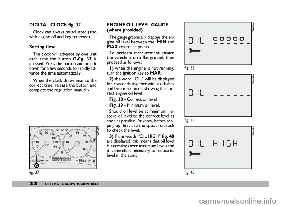
Wrapping the bench seat
If after tilting, bench seat wrapping
is required, pull the two levers A-
fig. 66set under the backrest (as
specified on the plate) and tilt forward
the entire bench seat row (fig. 67).
fig. 66
F0D0284m
fig. 67
F0D0285m
Removing the bench seat
IMPORTANTThe bench seat
(weighing 75 kg) shall be removed by
two people at least.
To remove the bench seat, lift and
then pull the two levers A-fig.68(as
specified on the label). Make sure both
levers B-fig.69are in “released” po-
sition (as specified on the label) (pin C
visible).The bench seat is properly released
when the red mark on label (A) on the
mobile part of the bench seat (fig. 70)
is aligned with the green mark (B) on
the fixed part of the bench seat.
fig. 68
F0D0286m
fig. 69
F0D0293m
fig. 70
F0D0296m
Page 51 of 258
50GETTING TO KNOW YOUR VEHICLE
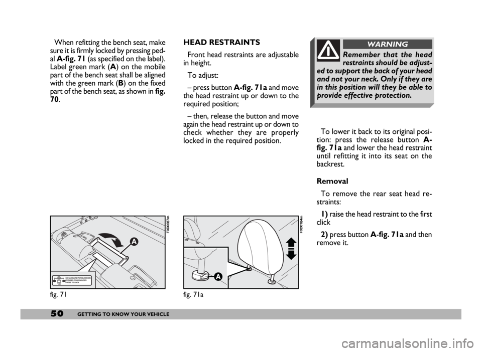
To lower it back to its original posi-
tion: press the release button A-
fig. 71aand lower the head restraint
until refitting it into its seat on the
backrest.
Removal
To remove the rear seat head re-
straints:
1) raise the head restraint to the first
click
2)press button A-fig. 71a and then
remove it.
Remember that the head
restraints should be adjust-
ed to support the back of your head
and not your neck. Only if they are
in this position will they be able to
provide effective protection.
WARNINGHEAD RESTRAINTS
Front head restraints are adjustable
in height.
To adjust:
– press button A-fig. 71aand move
the head restraint up or down to the
required position;
– then, release the button and move
again the head restraint up or down to
check whether they are properly
locked in the required position.
fig. 71
F0D0287m
fig. 71a
F0D0184m
When refitting the bench seat, make
sure it is firmly locked by pressing ped-
al A-fig. 71(as specified on the label).
Label green mark (A) on the mobile
part of the bench seat shall be aligned
with the green mark (B) on the fixed
part of the bench seat, as shown in fig.
70.
Page 52 of 258
51GETTING TO KNOW YOUR VEHICLE
HEIGHT ADJUSTABLE
STEERING WHEEL
The steering wheel of every version
can be adjusted vertically:
1)Move lever A-fig. 71b to position
1.
2)Adjust the steering wheel.
3)Take the lever back to position 2
to lock the steering wheel.
fig. 71b
F0D0040m
Only make adjustments
when the vehicle is sta-
tionary.
WARNING
DRIVING MIRROR
This mirror can be adjusted by means
of lever A-fig. 72.
1- normal position.
2- anti-dazzle position.
This mirror is also fitted with a safety
device that releases the mirror in the
event of an impact.
fig. 72
F0D0168m
It is absolutely forbidden to
carry out whatever after-
market operation involving steering
system or steering column modifi-
cations (e.g.: installation of anti-
theft Device) that could badly af-
fect performance and safety, cause
the lapse of warranty and also re-
sult in non-compliance of the car
with homologation requirements.
WARNING
Page 59 of 258

58GETTING TO KNOW YOUR VEHICLE
Turn knob fig. 83 under the roof to
turn the supplementary climate control
system on. It will only work when the
main system is running.
Air flow is distributed to the back
through the directional vents set under
the roof by lever A-fig. 84.
Like for Panorama and Combi, also the
Van versions can be equipped with an
optional climate control system to be set
in the load compartment and to be
switched on using the relevant console
controls.AIR CONDITIONING
(COOLING)
Control settings for quick cooling:
1)air temperature knob: pointer at
the blue sector
2)climate control system: press but-
ton √
3)air recirculation slider: at Ò
4) air distribution knob: pointer at O
5)fan knob: pointer at the required
speed.To reduce the cooling effect: posi-
tion the slider at Ú, to increase the
temperature and decrease the fan
speed.
Do not switch the climate control
system on for heating and ventilation.
Use the ordinary heating and ventila-
tion system (see previous section).
IMPORTANT The climate control
system is very useful for clearing the
windows rapidly because it dries the
air. Simply set the controls for demist-
ing and turn the climate control sys-
tem on with button √.
ADDITIONAL HEATER
Certain versions feature, under the
driver’s seat, an additional heater us-
ing the same heating system controls.
fig. 83
F0D0049m
fig. 84
F0D0075m
Page 67 of 258

66GETTING TO KNOW YOUR VEHICLE
Flashing the headlights fig. 94
Pull the stalk towards the steering
wheel (temporary position) to flash
the lights.Direction indicators fig. 95
Move the stalk as follows:
upwards - to turn the right-hand in-
dicators on
downwards - to turn the left-hand in-
dicators on.
Instrument panel warning light RE
will flash.
The direction indicators will auto-
matically be switched off when the ve-
hicle is straightened out.
If you wish to signal a lane change
where only a slight movement of the
steering wheel is required, move the
stalk up or down without pushing it far
enough to make it click. The stalk will
return to the neutral position as soon
as it is released.RIGHT-HAND STALK
Windscreen wiper/washer
fig. 96
The device will only work when the
ignition key is at MAR.
Positions
0- windscreen wiper off;
1- flick wipe;
2- slow continuous wipe;
3- fast continuous wipe;
4- temporary: when released the
stalk returns to position 0and auto-
matically switches the windscreen
wiper off.
fig. 94
F0D0016m
fig. 95
F0D0017m
fig. 96
F0D0018m
Page 68 of 258

67GETTING TO KNOW YOUR VEHICLE
REARVIEW
CAMERA
Vehicles equipped with CONNECT
NAV+ can be fitted with an optional
rearview camera. This camerafig. 98,
set on roof rear cross member dis-
plays on the CONNECT NAV+ mon-
itor the images of the rear part of the
vehicle, thus supporting the driver
during parking or reverse manoeuvres.
When the reverse gear is engaged, the
camera is automatically activated. In
the same way, the camera is deacti-
vated when disengaging the reverse
gear.
PARKING SENSORS
The parking system fig. 99detects
and informs the driver about the pres-
ence of obstacles in the rear part of
the vehicle.
It is a valid support to identify fences,
walls, posts, vases with plants and the
like or children playing behind the ve-
hicle.
fig. 98
F0D0173m
SMART WASH fig. 97
Pull the stalk towards the steering
wheel to send a jet of fluid to the
windscreen and operate the wiper
with a simple gesture. The windscreen
wiper will be operated automatically
by holding the washer stalk for longer
than half a second.
The windscreen wiper will flick three
times after the lever is released.
Operate the control repeatedly and
rapidly (for less than half a second) to
spray the windscreen several times
without operating the windscreen
wiper.
fig. 97
F0D0020m
fig. 99
F0D0223m