Page 69 of 293
Mist
Use this feature when weather conditions make occa-
sional usage of the wipers necessary. Pull down and
release the control lever for a single wiping cycle.
Speed Sensitive Intermittent Wiper System
Use the intermittent wiper when weather conditions
make a single wiping cycle, with a variable pause be-
tween cycles, desirable. Turn the lever to the delay
position, then select the delay interval. The delay can be
regulated from a maximum of approximately 18 seconds
between cycles, to a cycle every 1/2 second.
NOTE:The wiper delay times depend on vehicle speed.
If the vehicle is moving less than 16 km/h (10 mph),
delay times will be doubled.
TILT STEERING COLUMN
To tilt the column, push down on the lever below the turn
signal control and move the wheel up or down, as
desired. Push the lever back up to lock the column firmly
in place.
Tilt Steering Column Control
UNDERSTANDING THE FEATURES OF YOUR VEHICLE 69
3
Page 71 of 293
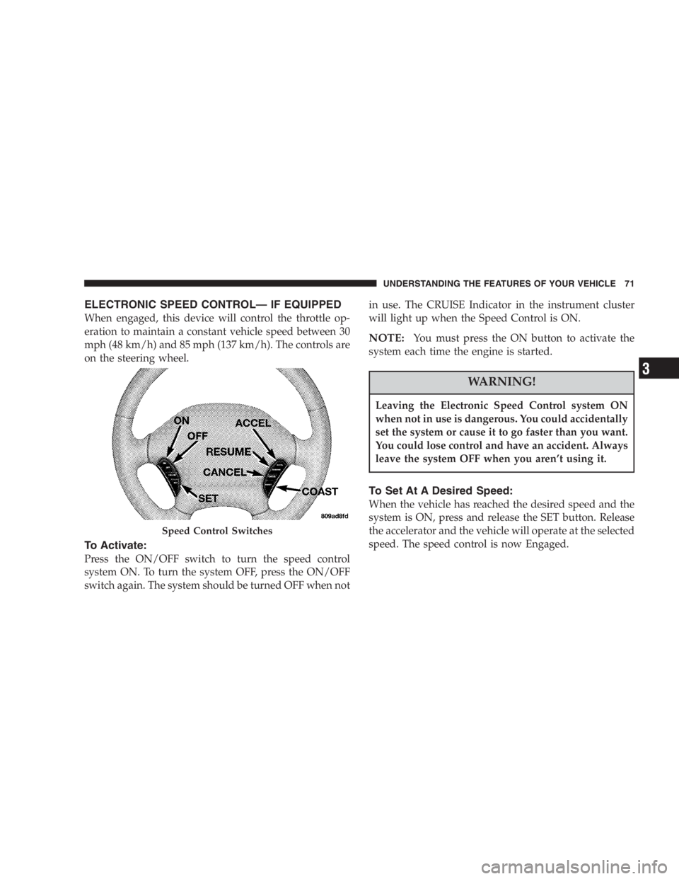
ELECTRONIC SPEED CONTROL—IF EQUIPPED
When engaged, this device will control the throttle op-
eration to maintain a constant vehicle speed between 30
mph (48 km/h) and 85 mph (137 km/h). The controls are
on the steering wheel.
To Activate:
Press the ON/OFF switch to turn the speed control
system ON. To turn the system OFF, press the ON/OFF
switch again. The system should be turned OFF when notin use. The CRUISE Indicator in the instrument cluster
will light up when the Speed Control is ON.
NOTE:You must press the ON button to activate the
system each time the engine is started.
WARNING!
Leaving the Electronic Speed Control system ON
when not in use is dangerous. You could accidentally
set the system or cause it to go faster than you want.
You could lose control and have an accident. Always
leave the system OFF when you aren’t using it.
To Set At A Desired Speed:
When the vehicle has reached the desired speed and the
system is ON, press and release the SET button. Release
the accelerator and the vehicle will operate at the selected
speed. The speed control is now Engaged.
Speed Control Switches
UNDERSTANDING THE FEATURES OF YOUR VEHICLE 71
3
Page 90 of 293

5. Tachometer
The red area of the scale shows the maximum permissible
engine revolutions-per-minute (rpm x 1000) for each gear
range. Before reaching the red area (over 6,500 rpm), ease
up on the accelerator to prevent engine over speed.
6. Turn Signal Indicators
The arrows will flash in unison with the exterior turn
signal, when using the turn signal lever.
7. High Beam Indicator
This light shows that the headlights are on high
beam. Pull the turn signal lever toward the
steering wheel to switch the headlights from high or
low beam.
8. Speedometer
Shows the vehicle speed in miles-per-hour and
kilometers-per-hour.
9. Charging System Light
This light shows the status of the electrical
charging system. The light should come on
briefly when the ignition is first turned on and remain
on briefly as a bulb check. If the light stays on orcomes on while driving, turn off some of the vehicle’s
electrical devices, such as the Fog Lights or Rear
Defroster. If the Charging System Light remains on, it
means that the vehicle is experiencing a problem with
the charging system. Obtain SERVICE IMMEDI-
ATELY. See your local authorized dealer.
10. Malfunction Indicator Light
This light is part of an onboard diagnostic
system called OBD that monitors engine and
automatic transmission control systems. The
light will illuminate as long as the key is in the ON
position, prior to engine start up. Approximately 15
seconds later the MIL may blink for 10 seconds then
resume to full illumination. (See“EMISSIONS IN-
SPECTION AND MAINTENANCE PROGRAMS”in
the“MAINTAINING YOUR VEHICLE”section of
your Owner Manual for more details). If the bulb does
not come on when turning the key from OFF to ON,
have the condition checked promptly.
Certain conditions such as a loose or missing gas cap or
poor fuel quality may illuminate the light after engine
start. The vehicle should be serviced if the light stays on
90 UNDERSTANDING YOUR INSTRUMENT PANEL
Page 122 of 293
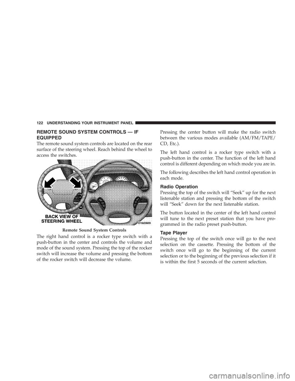
REMOTE SOUND SYSTEM CONTROLS—IF
EQUIPPED
The remote sound system controls are located on the rear
surface of the steering wheel. Reach behind the wheel to
access the switches.
The right hand control is a rocker type switch with a
push-button in the center and controls the volume and
mode of the sound system. Pressing the top of the rocker
switch will increase the volume and pressing the bottom
of the rocker switch will decrease the volume.Pressing the center button will make the radio switch
between the various modes available (AM/FM/TAPE/
CD, Etc.).
The left hand control is a rocker type switch with a
push-button in the center. The function of the left hand
control is different depending on which mode you are in.
The following describes the left hand control operation in
each mode.
Radio Operation
Pressing the top of the switch will“Seek”up for the next
listenable station and pressing the bottom of the switch
will“Seek”down for the next listenable station.
The button located in the center of the left hand control
will tune to the next preset station that you have pro-
grammed in the radio preset push-button.
Tape Player
Pressing the top of the switch once will go to the next
selection on the cassette. Pressing the bottom of the
switch once will go to the beginning of the current
selection or to the beginning of the previous selection if it
is within the first 5 seconds of the current selection.
Remote Sound System Controls
122 UNDERSTANDING YOUR INSTRUMENT PANEL
Page 150 of 293
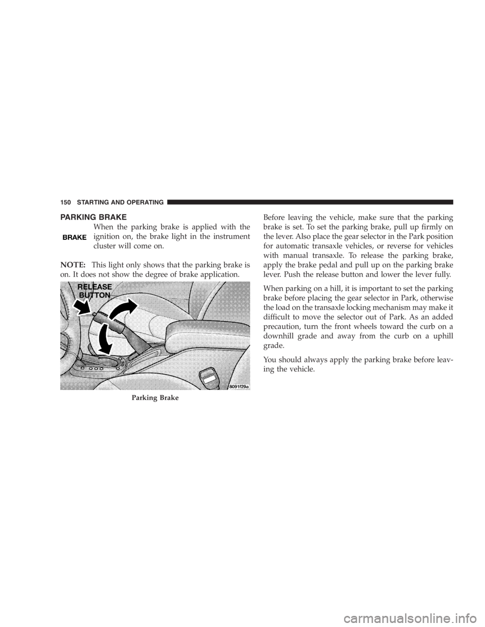
PARKING BRAKE
When the parking brake is applied with the
ignition on, the brake light in the instrument
cluster will come on.
NOTE:This light only shows that the parking brake is
on. It does not show the degree of brake application.Before leaving the vehicle, make sure that the parking
brake is set. To set the parking brake, pull up firmly on
the lever. Also place the gear selector in the Park position
for automatic transaxle vehicles, or reverse for vehicles
with manual transaxle. To release the parking brake,
apply the brake pedal and pull up on the parking brake
lever. Push the release button and lower the lever fully.
When parking on a hill, it is important to set the parking
brake before placing the gear selector in Park, otherwise
the load on the transaxle locking mechanism may make it
difficult to move the selector out of Park. As an added
precaution, turn the front wheels toward the curb on a
downhill grade and away from the curb on a uphill
grade.
You should always apply the parking brake before leav-
ing the vehicle.
Parking Brake
150 STARTING AND OPERATING
Page 152 of 293
Anti-Lock Brake System (ABS)—If Equipped
The ABS gives increased vehicle stability and brake
performance under most braking conditions. The system
automatically“pumps”the brakes during severe braking
conditions to prevent wheel lock-up.
All vehicle wheels and tires must be the same size and
tires must be properly inflated to produce accurate
signals for the ABS computer. However, the system will
compensate when the compact spare is in use.
During stops where ABS is activated, a vibration of the
brake pedal may be felt and associated system noises
may be heard.
WARNING!
Pumping of the brake pedal will diminish the effec-
tiveness of Anti-lock brakes and may lead to an
accident. Pumping makes the stopping distance
longer. Just press firmly on your brake pedal when
you need to slow down or stop.
WARNING!
•Anti-lock system (ABS) cannot prevent the natu-
ral laws of physics from acting on the vehicle, nor
can it increase braking or steering efficiency be-
yond that afforded by the condition of the vehicle
brakes and tires or the traction afforded.
•The ABS cannot prevent accidents, including
those resulting from excessive speed in turns,
following another vehicle too closely, or hydro-
planing. Only a safe, attentive, and skillful driver
can prevent accidents.
•The capabilities of an ABS equipped vehicle must
never be exploited in a reckless or dangerous
manner which could jeopardize the user’s safety
or the safety of others.
152 STARTING AND OPERATING
Page 153 of 293
POWER STEERING
The power assisted steering system of your vehicle
provides mechanical steering capability in the event
power assist is lost.
If for some reason the hydraulic pressure is interrupted,
it will still be possible to steer your vehicle. Under these
conditions you will observe a substantial increase in
steering effort.
TRACTION CONTROL—IF EQUIPPED
The Traction Control System will improve acceleration
and steering on slippery surfaces by reducing tire spin.
The system reduces wheel slip and maintains traction at
the driving (front) wheels by engaging the brake on the
wheel that is losing traction. When this occurs the
traction control indicator light located in the instrument
cluster will flash. The system operates at speeds below 35
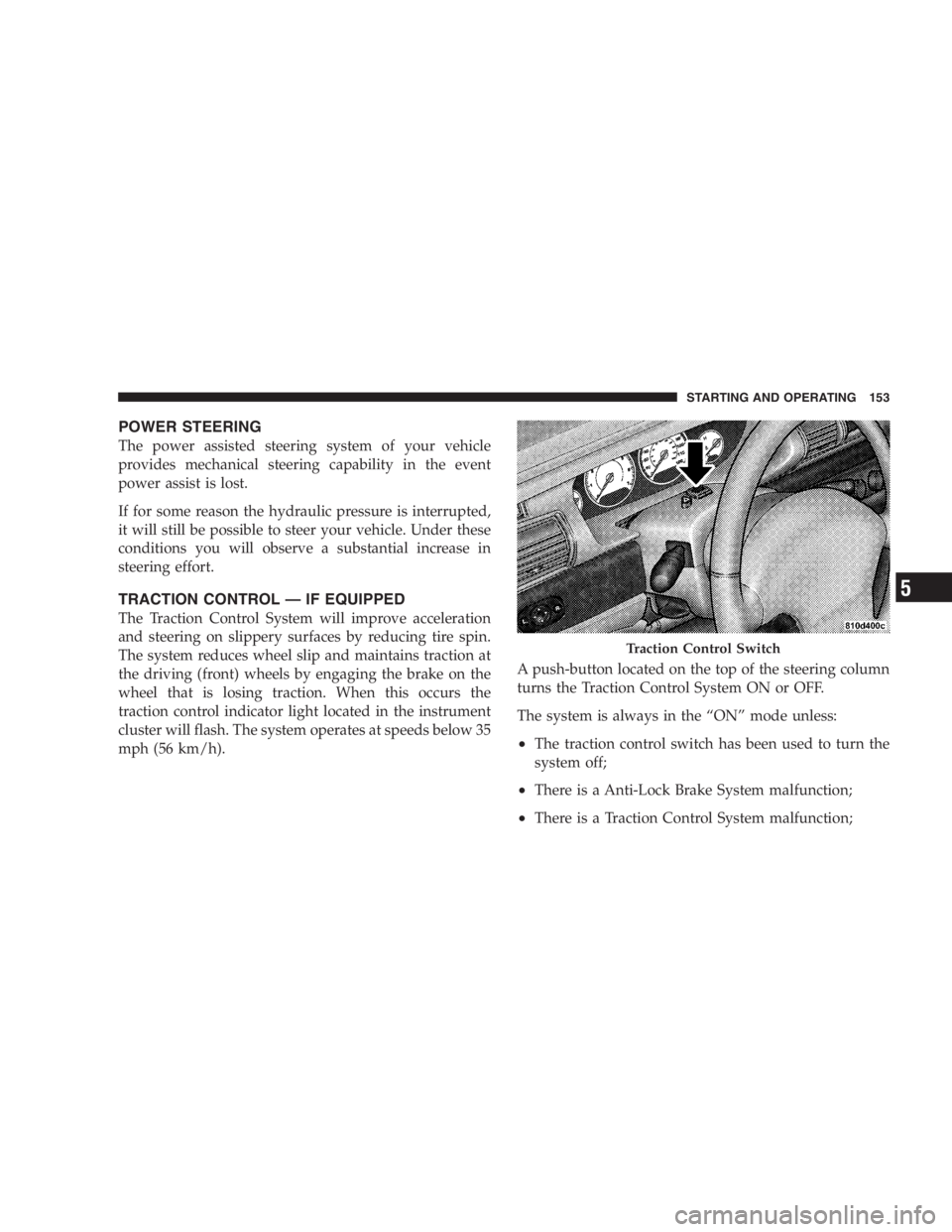
mph (56 km/h).A push-button located on the top of the steering column
turns the Traction Control System ON or OFF.
The system is always in the“ON”mode unless:
•The traction control switch has been used to turn the
system off;
•There is a Anti-Lock Brake System malfunction;
•There is a Traction Control System malfunction;
Traction Control Switch
STARTING AND OPERATING 153
5
Page 166 of 293
WARNING!
High speed driving with your vehicle under maxi-
mum load is dangerous. The added strain on your
tires could cause them to fail. You could have a
serious accident. Don’t drive a vehicle loaded to the
maximum capacity at continuous speeds above 75
mph (120 km/h).
Radial-Ply Tires
WARNING!
Combining radial ply tires with other types of tires
on your vehicle will cause your vehicle to handle
poorly. The instability could cause an accident. Al-
ways use radial ply tires in sets of four (or 6, in case
of trucks with dual rear wheels). Never combine
them with other types of tires.
Cuts and punctures in radial tires are repairable only in
the tread area because of sidewall flexing. Consult your
authorized tire dealer for radial tire repairs.
Compact Spare Tire—If Equipped
The compact spare is for temporary emergency use with
radial tires. It is engineered to be used on your style
vehicle only. Since this tire has limited tread life, the
original tire should be repaired (or replaced) and rein-
stalled at the first opportunity.
WARNING!
Temporary use spare tires are for emergency use
only. With these tires, do not drive more than 50 mph
(80 km/h). Temporary-use spare tires have limited
tread life. When two or more tread wear indicators
appear in adjacent grooves, the temporary use spare
tire needs to be replaced. Be sure to follow the
warnings which apply to your spare. Failure to do so
could result in spare tire failure and loss of vehicle
control.
166 STARTING AND OPERATING