2005 CHRYSLER VOYAGER remove interior panels
[x] Cancel search: remove interior panelsPage 475 of 2339

NOTE: Push in on the push-pins at the clutch hous-
ing (plastic side) until you hear one click. Push in
on the push-pin fasteners at the motor mount
(sheet metal side) until you hear two clicks. This
assures proper installation/attachment of the motor
to the sliding door.
(3) Install the flex shaft by lining up the square
shaped drive shaft with the corresponding hole in the
door motor drive unit and push straight in.
(4) Install the E-clip to secure flex-shaft.
(5) Install the weather shield as necessary.
(6) Install the door trim panel on the sliding door,
(Refer to 23 - BODY/DOORS - SLIDING/TRIM
PANEL - INSTALLATION) for the procedure.
(7) Connect the battery negative cable.
FULL OPEN SWITCH
DESCRIPTION
The full open switch is located in the hold open
latch (Fig. 10) under the sliding door lower hinge.
When the power sliding door control module receives
a ground signal input from the full open switch, and
as long as the cinching latch actuator is not in power
mode or the handle switch is open, the signal indi-
cates that the door is at the full open position.The full open switch is incorporated into the hold
open latch. If the full open switch is inoperative, the
entire hold open latch assembly must be replaced.
OPERATION
The full open switch is triggered by a pawl lever in
the hold open latch. When the full open switch is
closed (circuit to ground) the ratchet has engaged on
the hold open striker and the pawl lever has engaged
on the ratchet, locking the latch from opening and
holding the door in the full open position.
B-PILLAR SWITCH
DESCRIPTION
The B-pillar switches are located on the interior of
the vehicle, on the B-pillar trim panels. These
switches serve as an open and close command switch
for the appropriate power sliding door.
OPERATION
When the B-pillar switch is depressed a signal is
sent to the Body Control Module (BCM), this signal
is then sent to the power sliding door control module,
telling it to start a power open or close cycle. The
child lockout feature must be disabled and the slid-
ing door must be unlocked in order for the B-pillar
switch to function.
REMOVAL
(1) Disconnect and isolate the battery negative
cable.
(2) Using a trim stick (special tool # C-4755) or
equivalent, gently pry the leading upper edge of the
B-pillar switch away from the B-pillar trim.
(3) Once the upper edge is free from B-pillar trim,
rock the switch out of the switch opening.
(4) Disconnect the B-pillar switch electrical con-
nector. First, slide the connector lock away from the
switch then, depress connector retaining tab while
pulling straight apart.
(5) Remove the B-pillar switch from the vehicle.
INSTALLATION
(1) Connect the B-pillar switch electrical connector.
Slide connector lock toward the switch to lock in
place.
(2) Hook the lower edge of the B-pillar switch on
the B-pillar trim and then push the switch firmly
into position.
(3) Connect the battery negative cable.
Fig. 10 FULL OPEN SWITCH POSITION &
ORIENTATION
1 - HOLD OPEN LATCH ASSEMBLY
2 - HOLD OPEN LATCH CABLE
3 - FULL OPEN SWITCH
8N - 52 POWER SLIDING DOOR SYSTEMRS
SLIDING DOOR MOTOR (Continued)
Page 1780 of 2339
BODY
TABLE OF CONTENTS
page page
BODY
DESCRIPTION - VEHICLE IDENTIFICATION....1
WARNING
SAFETY PRECAUTIONS AND WARNINGS . . . 1
DIAGNOSIS AND TESTING
WATER LEAKS........................1
WIND NOISE..........................2
STANDARD PROCEDURE
STANDARD PROCEDURE - PLASTIC BODY
PANEL REPAIR........................3
STANDARD PROCEDURE - HEAT STAKING . . 9
SPECIFICATIONS
TORQUE............................10
BODY LUBRICATION...................12
SPECIAL TOOLS
BODY..............................13DOOR - FRONT.........................14
DOORS - SLIDING.......................24
DECKLID/HATCH/LIFTGATE/TAILGATE.......40
EXTERIOR.............................45
HOOD.................................62
INSTRUMENT PANEL.....................65
INTERIOR..............................78
PAINT................................100
SEATS...............................102
STATIONARY GLASS....................161
WEATHERSTRIP/SEALS..................166
SUNROOF.............................169
BODY STRUCTURE.....................177
BODY
DESCRIPTION - VEHICLE IDENTIFICATION
Throughout this group, references to the
DaimlerChrysler Corporation vehicle family identifi-
cation code are used when describing a procedure
that is unique to that vehicle. Refer to Introduction
Group of this manual for detailed information on
vehicle identification. If a procedure is common to all
vehicles covered in this manual, no reference will be
made to a vehicle family code.
WARNING
SAFETY PRECAUTIONS AND WARNINGS
WARNING: USE A OSHA APPROVED BREATHING
FILTER WHEN SPRAYING PAINT OR SOLVENTS IN
A CONFINED AREA. PERSONAL INJURY CAN
RESULT.
AVOID PROLONGED SKIN CONTACT WITH PETRO-
LEUM OR ALCOHOL ± BASED CLEANING SOL-
VENTS. PERSONAL INJURY CAN RESULT.
DO NOT STAND UNDER A HOISTED VEHICLE THAT
IS NOT PROPERLY SUPPORTED ON SAFETY
STANDS. PERSONAL INJURY CAN RESULT.
CAUTION: When holes must be drilled or punched
in an inner body panel, verify depth of space to the
outer body panel, electrical wiring, or other compo-nents. Damage to vehicle can result.
Do not weld exterior panels unless combustible
material on the interior of vehicle is removed from
the repair area. Fire or hazardous conditions, can
result.
Always have a fire extinguisher ready for use when
welding.
Disconnect the negative (-) cable clamp from the
battery when servicing electrical components that
are live when the ignition is OFF. Damage to electri-
cal system can result.
Do not use abrasive chemicals or compounds on
painted surfaces. Damage to finish can result.
Do not use harsh alkaline based cleaning solvents
on painted or upholstered surfaces. Damage to fin-
ish or color can result.
Do not hammer or pound on plastic trim panel
when servicing interior trim. Plastic panels can
break.
DIAGNOSIS AND TESTING
WATER LEAKS
Water leaks can be caused by poor sealing,
improper body component alignment, body seam
porosity, missing plugs, or blocked drain holes. Cen-
trifugal and gravitational force can cause water to
drip from a location away from the actual leak point,
making leak detection difficult. All body sealing
points should be water tight in normal wet-driving
conditions. Water flowing downward from the front of
RSBODY23-1
Page 1781 of 2339
the vehicle should not enter the passenger or luggage
compartment. Moving sealing surfaces will not
always seal water tight under all conditions. At
times, side glass or door seals will allow water to
enter the passenger compartment during high pres-
sure washing or hard driving rain (severe) condi-
tions. Overcompensating on door or glass
adjustments to stop a water leak that occurs under
severe conditions can cause premature seal wear and
excessive closing or latching effort. After completing
a repair, water test vehicle to verify leak has stopped
before returning vehicle to use.
VISUAL INSPECTION BEFORE WATER LEAK TESTS
Verify that floor and body plugs are in place, body
drains are clear, and body components are properly
aligned and sealed. If component alignment or seal-
ing is necessary, refer to the appropriate section of
this group for proper procedures.
WATER LEAK TESTS
WARNING: DO NOT USE ELECTRIC SHOP LIGHTS
OR TOOLS IN WATER TEST AREA. PERSONAL
INJURY CAN RESULT.
When the conditions causing a water leak have
been determined, simulate the conditions as closely
as possible.
²If a leak occurs with the vehicle parked in a
steady light rain, flood the leak area with an open-
ended garden hose.
²If a leak occurs while driving at highway speeds
in a steady rain, test the leak area with a reasonable
velocity stream or fan spray of water. Direct the
spray in a direction comparable to actual conditions.
²If a leak occurs when the vehicle is parked on an
incline, hoist the end or side of the vehicle to simu-
late this condition. This method can be used when
the leak occurs when the vehicle accelerates, stops or
turns. If the leak occurs on acceleration, hoist the
front of the vehicle. If the leak occurs when braking,
hoist the back of the vehicle. If the leak occurs on left
turns, hoist the left side of the vehicle. If the leak
occurs on right turns, hoist the right side of the vehi-
cle. For hoisting recommendations (Refer to LUBRI-
CATION & MAINTENANCE/HOISTING -
STANDARD PROCEDURE).
WATER LEAK DETECTION
To detect a water leak point-of-entry, do a water
test and watch for water tracks or droplets forming
on the inside of the vehicle. If necessary, remove inte-
rior trim covers or panels to gain visual access to the
leak area. If the hose cannot be positioned without
being held, have someone help do the water test.Some water leaks must be tested for a considerable
length of time to become apparent. When a leak
appears, find the highest point of the water track or
drop. The highest point usually will show the point of
entry. After leak point has been found, repair the
leak and water test to verify that the leak has
stopped.
Locating the entry point of water that is leaking
into a cavity between panels can be difficult. The
trapped water may splash or run from the cavity,
often at a distance from the entry point. Most water
leaks of this type become apparent after accelerating,
stopping, turning, or when on an incline.
MIRROR INSPECTION METHOD
When a leak point area is visually obstructed, use
a suitable mirror to gain visual access. A mirror can
also be used to deflect light to a limited-access area
to assist in locating a leak point.
BRIGHT LIGHT LEAK TEST METHOD
Some water leaks in the luggage compartment can
be detected without water testing. Position the vehi-
cle in a brightly lit area. From inside the darkened
luggage compartment inspect around seals and body
seams. If necessary, have a helper direct a drop light
over the suspected leak areas around the luggage
compartment. If light is visible through a normally
sealed location, water could enter through the open-
ing.
PRESSURIZED LEAK TEST METHOD
When a water leak into the passenger compart-
ment cannot be detected by water testing, pressurize
the passenger compartment and soap test exterior of
the vehicle. To pressurize the passenger compart-
ment, close all doors and windows, start engine, and
set heater control to high blower in HEAT position. If
engine can not be started, connect a charger to the
battery to ensure adequate voltage to the blower.
With interior pressurized, apply dish detergent solu-
tion to suspected leak area on the exterior of the
vehicle. Apply detergent solution with spray device or
soft bristle brush. If soap bubbles occur at a body
seam, joint, seal or gasket, the leak entry point could
be at that location.
WIND NOISE
Wind noise is the result of most air leaks. Air leaks
can be caused by poor sealing, improper body compo-
nent alignment, body seam porosity, or missing plugs
in the engine compartment or door hinge pillar areas.
All body sealing points should be airtight in normal
driving conditions. Moving sealing surfaces will not
always seal airtight under all conditions. At times,
side glass or door seals will allow wind noise to be
23 - 2 BODYRS
BODY (Continued)
Page 1782 of 2339
noticed in the passenger compartment during high
cross winds. Over compensating on door or glass
adjustments to stop wind noise that occurs under
severe conditions can cause premature seal wear and
excessive closing or latching effort. After a repair pro-
cedure has been performed, test vehicle to verify
noise has stopped before returning vehicle to use.
VISUAL INSPECTION BEFORE TESTS
Verify that floor and body plugs are in place and
body components are aligned and sealed. If compo-
nent alignment or sealing is necessary, refer to the
appropriate section of this group for proper proce-
dures.
ROAD TESTING WIND NOISE
(1) Drive the vehicle to verify the general location
of the wind noise.
(2) Apply 50 mm (2 in.) masking tape in 150 mm
(6 in.) lengths along weatherstrips, weld seams or
moldings. After each length is applied, drive the vehi-
cle. If noise goes away after a piece of tape is applied,
remove tape, locate, and repair defect.
POSSIBLE CAUSE OF WIND NOISE
²Moldings standing away from body surface can
catch wind and whistle.
²Gaps in sealed areas behind overhanging body
flanges can cause wind-rushing sounds.
²Misaligned movable components.
²Missing or improperly installed plugs in pillars.
²Weld burn through holes.
STANDARD PROCEDURE
STANDARD PROCEDURE - PLASTIC BODY
PANEL REPAIR
There are many different types of plastics used in
today's automotive environment. We group plastics in
three different categories: Rigid, Semi-Rigid, and
Flexible. Any of these plastics may require the use of
an adhesion promoter for repair. These types of plas-
tic are used extensively on DaimlerChrysler Motors
vehicles. Always follow repair material manufactur-
er's plastic identification and repair procedures.
Rigid Plastics:
Examples of rigid plastic use: Fascias, Hoods,
Doors, and other Body Panels, which include SMC,
ABS, and Polycarbonates.
Semi-Rigid Plastics:
Examples of semi-rigid plastic use: Interior Panels,
Under Hood Panels, and other Body Trim Panels.
Flexible Plastics:
Examples of flexible plastic use: Fascias, Body
Moldings, and upper and lower Fascia Covers.
Repair Procedure:
The repair procedure for all three categories of
plastics is basically the same. The one difference is
the material used for the repair. The materials must
be specific for each substrate, rigid repair material
for rigid plastic repair, semi-rigid repair material for
semi-rigid plastic repair and flexible repair material
for flexible plastic repair.
Adhesion Promoter/Surface Modifier:
Adhesion Promoters/Surface Modifiers are required
for certain plastics. All three categories may have
plastics that require the use of adhesion promoter/
surface modifiers. Always follow repair material man-
ufacturer's plastic identification and repair
procedures.
SAFETY PRECAUTION AND WARNINGS
WARNING:
²EYE PROTECTION SHOULD BE USED WHEN
SERVICING COMPONENTS. PERSONAL INJURY
CAN RESULT.
²USE AN OSHA APPROVED BREATHING MASK
WHEN MIXING EPOXY, GRINDING, AND SPRAYING
PAINT OR SOLVENTS IN A CONFINED AREA. PER-
SONAL INJURY CAN RESULT.
²AVOID PROLONGED SKIN CONTACT WITH
RESIN, PETROLEUM, OR ALCOHOL BASED SOL-
VENTS. PERSONAL INJURY CAN RESULT.
²DO NOT VENTURE UNDER A HOISTED VEHI-
CLE THAT IS NOT PROPERLY SUPPORTED ON
SAFETY STANDS. PERSONAL INJURY CAN
RESULT.
NOTE:
²When holes must be drilled or cut in body pan-
els, verify locations of internal body components
and electrical wiring. Damage to vehicle can result.
²Do not use abrasive chemicals or compounds
on undamaged painted surfaces around repair
areas. Damage to finish can result.
RSBODY23-3
BODY (Continued)
Page 1786 of 2339
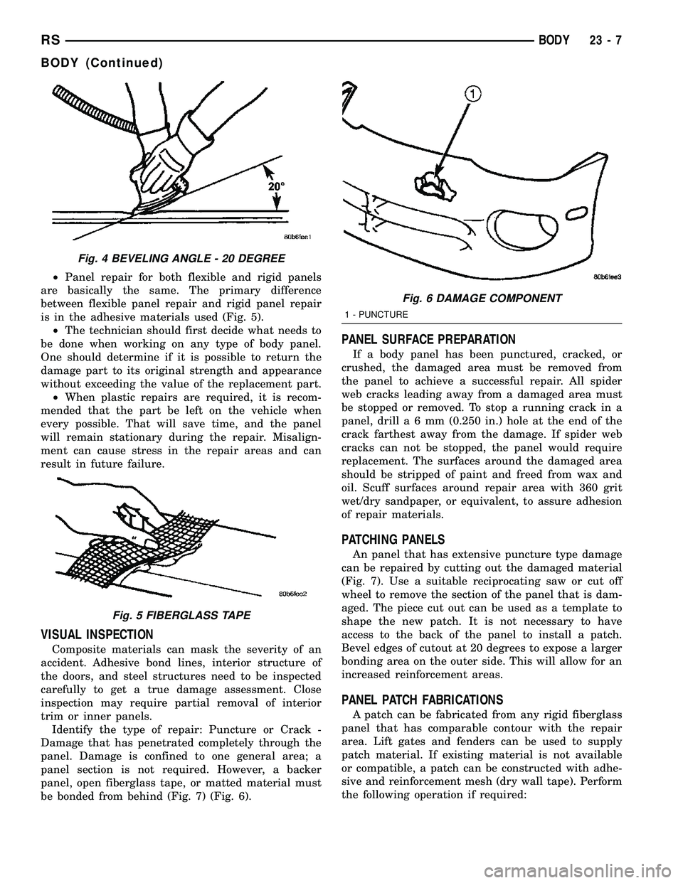
²Panel repair for both flexible and rigid panels
are basically the same. The primary difference
between flexible panel repair and rigid panel repair
is in the adhesive materials used (Fig. 5).
²The technician should first decide what needs to
be done when working on any type of body panel.
One should determine if it is possible to return the
damage part to its original strength and appearance
without exceeding the value of the replacement part.
²When plastic repairs are required, it is recom-
mended that the part be left on the vehicle when
every possible. That will save time, and the panel
will remain stationary during the repair. Misalign-
ment can cause stress in the repair areas and can
result in future failure.
VISUAL INSPECTION
Composite materials can mask the severity of an
accident. Adhesive bond lines, interior structure of
the doors, and steel structures need to be inspected
carefully to get a true damage assessment. Close
inspection may require partial removal of interior
trim or inner panels.
Identify the type of repair: Puncture or Crack -
Damage that has penetrated completely through the
panel. Damage is confined to one general area; a
panel section is not required. However, a backer
panel, open fiberglass tape, or matted material must
be bonded from behind (Fig. 7) (Fig. 6).
PANEL SURFACE PREPARATION
If a body panel has been punctured, cracked, or
crushed, the damaged area must be removed from
the panel to achieve a successful repair. All spider
web cracks leading away from a damaged area must
be stopped or removed. To stop a running crack in a
panel, drilla6mm(0.250 in.) hole at the end of the
crack farthest away from the damage. If spider web
cracks can not be stopped, the panel would require
replacement. The surfaces around the damaged area
should be stripped of paint and freed from wax and
oil. Scuff surfaces around repair area with 360 grit
wet/dry sandpaper, or equivalent, to assure adhesion
of repair materials.
PATCHING PANELS
An panel that has extensive puncture type damage
can be repaired by cutting out the damaged material
(Fig. 7). Use a suitable reciprocating saw or cut off
wheel to remove the section of the panel that is dam-
aged. The piece cut out can be used as a template to
shape the new patch. It is not necessary to have
access to the back of the panel to install a patch.
Bevel edges of cutout at 20 degrees to expose a larger
bonding area on the outer side. This will allow for an
increased reinforcement areas.
PANEL PATCH FABRICATIONS
A patch can be fabricated from any rigid fiberglass
panel that has comparable contour with the repair
area. Lift gates and fenders can be used to supply
patch material. If existing material is not available
or compatible, a patch can be constructed with adhe-
sive and reinforcement mesh (dry wall tape). Perform
the following operation if required:
Fig. 4 BEVELING ANGLE - 20 DEGREE
Fig. 5 FIBERGLASS TAPE
Fig. 6 DAMAGE COMPONENT
1 - PUNCTURE
RSBODY23-7
BODY (Continued)
Page 1839 of 2339
INSTALLATION
SHORT WHEELBASE
(1) Position the air exhauster to the hole in the
lower aperture panel (Fig. 21).
(2) Using hand pressure, press the air exhauster
into the opening in the lower aperture panel until
the snap features are fully engaged.
(3) Reinstall the rear fascia onto the body. (Refer
to 13 - FRAMES & BUMPERS/BUMPERS/REAR
FASCIA - INSTALLATION).
LONG WHEELBASE
NOTE: Models with the optional rear heater and air
conditioner do not have an air exhauster on the
right side of the vehicle, but have a plastic plug
installed in the right lower aperture panel. This plug
is installed using the same procedure used to
install the air exhauster onto the short wheelbase
model. Refer to SHORT WHEELBASE.
(1) Position the air exhauster to the hole in the
lower aperture panel (Fig. 22).
(2) Using hand pressure, press the air exhauster
into the opening in the lower aperture panel until
the snap features are fully engaged.
(3) Reinstall the quarter trim panel onto the inside
of the left or right quarter inner panel. (Refer to 23 -
BODY/INTERIOR/RIGHT QUARTER TRIM PANEL
- INSTALLATION) or (Refer to 23 - BODY/INTERI-
OR/LEFT QUARTER TRIM PANEL - INSTALLA-
TION).
ROOF JOINT MOLDING
REMOVAL
The RAP molding is set with body side molding
tape. The temperature in the work area and the vehi-
cle should be at least 21É C (70É F) to avoid damag-
ing the RAP moldings.
(1) Warm the affected stick-on molding and body
metal to approximately 38É C (100É F) using a suit-
able heat lamp or heat gun.
(2) Pull stick-on molding from painted surface.
(3) Remove adhesive tape residue from painted
surface of vehicle. Use a 3M Scotch-BriteŸ Molding
Adhesive and Stripe Removal Discs, or equivalent, to
clean adhesive residue from painted surfaces. The
adhesive removal discs are available from automotive
paint suppliers. Refer to instructions supplied with
the discs for proper usage.
INSTALLATION
The RAP molding is set with body side molding
tape. The temperature in the work area and the vehi-
cle should be at least 21É C (70É F) to avoid damag-
ing the RAP moldings.
(1) If molding is to be reused;
(a) Remove tape residue from molding.
(b) Clean back of molding with MopartSuper
Kleen solvent, or equivalent.
(c) Wipe molding dry with lint free cloth.
(d) Apply new body side molding (two sided
adhesive) tape to back of molding.
(2) Clean body surface with MopartSuper Kleen
solvent, or equivalent. Wipe surface dry with lint free
cloth.
(3) Remove protective cover from tape on back of
molding.
(4) Apply molding to body from front of vehicle to
rear.
(5) Using a roller tool, roll molding onto body
panel with enough force to assure adhesion and not
bend roof panels.
SIDE VIEW MIRROR
REMOVAL
(1) Using a trim stick C-4755 or equivalent, lift up
the end of the instrument panel top pad enough to
gain access to the mirror electrical connector, if
equipped. (Refer to 23 - BODY/INSTRUMENT PAN-
EL/INSTRUMENT PANEL TOP COVER -
REMOVAL)
(2) Disconnect the electrical connector, if equipped.
(3) Using a trim stick or equivalent, remove the
trim cover (Fig. 23).
(4) Remove the bolts.
(5) Remove the mirror from the pillar.
INSTALLATION
(1) Route the mirror wire harness, if equipped,
through the a-pillar and place side view mirror in
position on vehicle (Fig. 23).
(2) Install the bolts and tighten to 10 N´m (85 in.
lbs.).
(3) Install the mirror trim cover.
(4) Connect the electrical connector, if equipped.
(5) Install the instrument panel top cover, if
equipped with the electric mirror. (Refer to 23 -
BODY/INSTRUMENT PANEL/INSTRUMENT
PANEL TOP COVER - INSTALLATION)
23 - 60 EXTERIORRS
REAR QUARTER PANEL/FENDER AIR EXHAUSTER (Continued)
Page 1860 of 2339
CARPETS AND FLOOR MATS
REMOVAL
(1) Remove front seats. (Refer to 23 - BODY/
SEATS/SEAT - REMOVAL)
(2) Remove front center console.
(3) Remove heel blocker (plastic block below accel-
erator pedal).
(4) Remove the remaining seats. Refer to the Own-
er's Manual for the proper procedures.
(5) Remove front cowl panels and sill plates.
(6) Remove sliding door sill plates. (Refer to 23 -
BODY/INTERIOR/SLIDING DOOR SILL PLATE -
REMOVAL)
(7) Remove the cargo organizer, if equipped.
(8) Remove liftgate scuff plate. (Refer to 23 -
BODY/INTERIOR/LIFTGATE SCUFF PLATE -
REMOVAL)
(9) Remove lower B-pillar trim covers.
(10) Remove D-pillar trim covers.
(11) Remove Quarter trim panels.
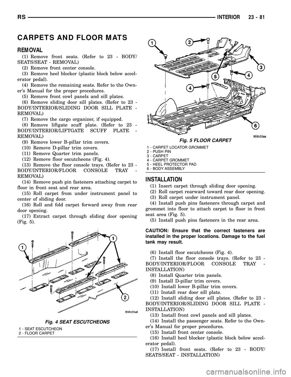
(12) Remove floor escutcheons (Fig. 4).
(13) Remove the floor console trays. (Refer to 23 -
BODY/INTERIOR/FLOOR CONSOLE TRAY -
REMOVAL)
(14) Remove push pin fasteners attaching carpet to
floor in front seat and rear area.
(15) Roll carpet from under instrument panel to
center of sliding door.
(16) Roll and fold carpet forward away from rear
door opening.
(17) Extract carpet through sliding door opening
(Fig. 5).
INSTALLATION
(1) Insert carpet through sliding door opening.
(2) Roll carpet rearward toward rear door opening.
(3) Roll carpet under instrument panel.
(4) Install push pins fasteners through carpet and
grommet into floor to attach carpet to floor in front
seat area (Fig. 5).
(5) Install push pins fasteners in the rear area.
CAUTION: Ensure that the correct fasteners are
installed in the proper locations. Damage to the fuel
tank may result.
(6) Install floor escutcheons (Fig. 4).
(7) Install the floor console trays. (Refer to 23 -
BODY/INTERIOR/FLOOR CONSOLE TRAY -
INSTALLATION)
(8) Install Quarter trim panels.
(9) Install D-pillar trim covers.
(10) Install lower B-pillar trim covers.
(11) Install rear door sill plate.
(12) Install sliding door sill plates. (Refer to 23 -
BODY/INTERIOR/SLIDING DOOR SILL PLATE -
INSTALLATION)
(13) Install front cowl panels and sill plates.
(14) Install the passenger seats. Refer to the Own-
er's Manual for proper procedures.
(15) Install front center console.
(16) Install heel blocker (plastic block below accel-
erator pedal).
(17) Install front seats. (Refer to 23 - BODY/
SEATS/SEAT - INSTALLATION)
Fig. 4 SEAT ESCUTCHEONS
1 - SEAT ESCUTCHEON
2 - FLOOR CARPET
Fig. 5 FLOOR CARPET
1 - CARPET LOCATOR GROMMET
2 - PUSH PIN
3 - CARPET
4 - CARPET GROMMET
5 - HEEL PROTECTOR PAD
6 - BODY ASSEMBLY
RSINTERIOR23-81
Page 1861 of 2339
CARPETS - FOLD-IN-FLOOR
REMOVAL
(1) Remove floor mats.
(2) Remove front seats. (Refer to 23 - BODY/
SEATS/SEAT - REMOVAL)
(3) Remove instrument panel lower console. (Refer
to 23 - BODY/INSTRUMENT PANEL/STORAGE
BIN - REMOVAL).
(4) Remove the floor console base tray and discon-
nect wire connector from the base tray.(Refer to 23 -
BODY/INTERIOR/FLOOR CONSOLE BASE TRAY -
REMOVAL)
(5) Remove heel blocker (plastic block below accel-
erator pedal).
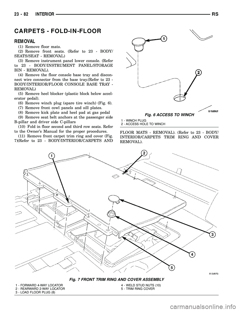
(6) Remove winch plug (spare tire winch) (Fig. 6).
(7) Remove front cowl panels and sill plates.
(8) Remove kick plate and heel pad at gas pedal
(9) Remove seat belt anchors at the passenger side
B-pillar and driver side C-pillars
(10) Fold in floor second and third row seats. Refer
to the Owner's Manual for the proper procedures.
(11) Remove front carpet trim ring and cover (Fig.
7)(Refer to 23 - BODY/INTERIOR/CARPETS ANDFLOOR MATS - REMOVAL). (Refer to 23 - BODY/
INTERIOR/CARPETS TRIM RING AND COVER
REMOVAL).
Fig. 6 ACCESS TO WINCH
1 - WINCH PLUG
2 - ACCESS HOLE TO WINCH
Fig. 7 FRONT TRIM RING AND COVER ASSEMBLY
1 - FORWARD 4-WAY LOCATOR
2 - REARWARD 2-WAY LOCATOR
3 - LOAD FLOOR PLUG (8)4 - WELD STUD NUTS (10)
5 - TRIM RING COVER
23 - 82 INTERIORRS