2005 CHRYSLER VOYAGER key
[x] Cancel search: keyPage 1234 of 2339
(4) Remove oil pan (Refer to 9 - ENGINE/LUBRI-
CATION/OIL PAN - REMOVAL).
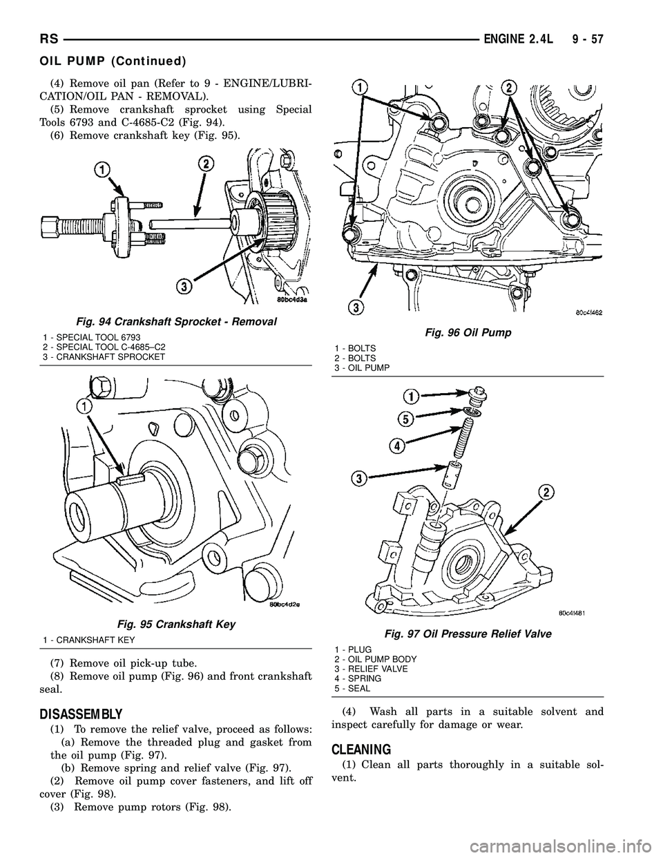
(5) Remove crankshaft sprocket using Special
Tools 6793 and C-4685-C2 (Fig. 94).
(6) Remove crankshaft key (Fig. 95).
(7) Remove oil pick-up tube.
(8) Remove oil pump (Fig. 96) and front crankshaft
seal.
DISASSEMBLY
(1) To remove the relief valve, proceed as follows:
(a) Remove the threaded plug and gasket from
the oil pump (Fig. 97).
(b) Remove spring and relief valve (Fig. 97).
(2) Remove oil pump cover fasteners, and lift off
cover (Fig. 98).
(3) Remove pump rotors (Fig. 98).(4) Wash all parts in a suitable solvent and
inspect carefully for damage or wear.
CLEANING
(1) Clean all parts thoroughly in a suitable sol-
vent.
Fig. 94 Crankshaft Sprocket - Removal
1 - SPECIAL TOOL 6793
2 - SPECIAL TOOL C-4685±C2
3 - CRANKSHAFT SPROCKET
Fig. 95 Crankshaft Key
1 - CRANKSHAFT KEY
Fig. 96 Oil Pump
1 - BOLTS
2 - BOLTS
3 - OIL PUMP
Fig. 97 Oil Pressure Relief Valve
1 - PLUG
2 - OIL PUMP BODY
3 - RELIEF VALVE
4 - SPRING
5 - SEAL
RSENGINE 2.4L9-57
OIL PUMP (Continued)
Page 1236 of 2339
INSTALLATION
(1) Make sure all surfaces are clean and free of oil
and dirt.
(2) Apply MopartGasket Maker to oil pump as
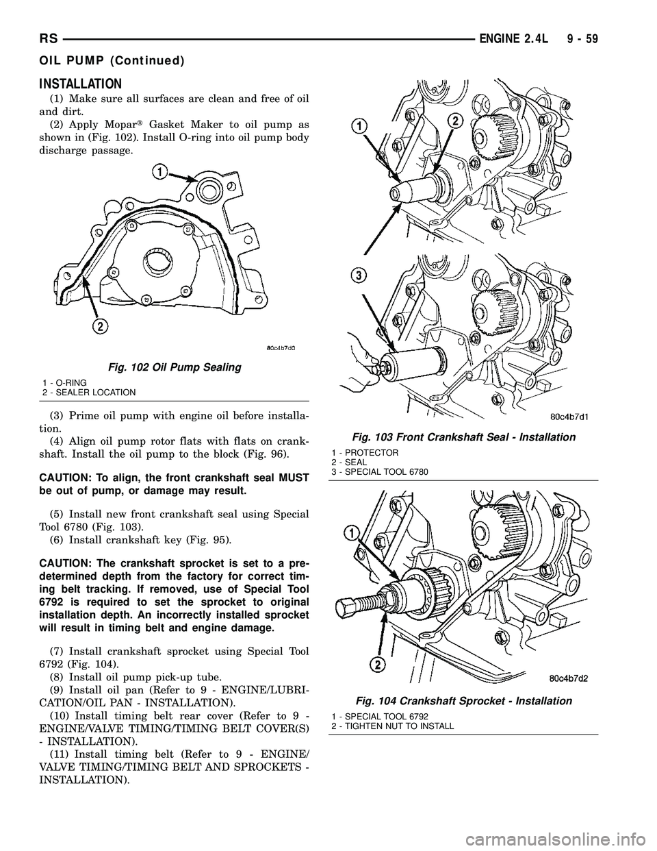
shown in (Fig. 102). Install O-ring into oil pump body
discharge passage.
(3) Prime oil pump with engine oil before installa-
tion.
(4) Align oil pump rotor flats with flats on crank-
shaft. Install the oil pump to the block (Fig. 96).
CAUTION: To align, the front crankshaft seal MUST
be out of pump, or damage may result.
(5) Install new front crankshaft seal using Special
Tool 6780 (Fig. 103).
(6) Install crankshaft key (Fig. 95).
CAUTION: The crankshaft sprocket is set to a pre-
determined depth from the factory for correct tim-
ing belt tracking. If removed, use of Special Tool
6792 is required to set the sprocket to original
installation depth. An incorrectly installed sprocket
will result in timing belt and engine damage.
(7) Install crankshaft sprocket using Special Tool
6792 (Fig. 104).
(8) Install oil pump pick-up tube.
(9) Install oil pan (Refer to 9 - ENGINE/LUBRI-
CATION/OIL PAN - INSTALLATION).
(10) Install timing belt rear cover (Refer to 9 -
ENGINE/VALVE TIMING/TIMING BELT COVER(S)
- INSTALLATION).
(11) Install timing belt (Refer to 9 - ENGINE/
VALVE TIMING/TIMING BELT AND SPROCKETS -
INSTALLATION).
Fig. 102 Oil Pump Sealing
1 - O-RING
2 - SEALER LOCATION
Fig. 103 Front Crankshaft Seal - Installation
1 - PROTECTOR
2 - SEAL
3 - SPECIAL TOOL 6780
Fig. 104 Crankshaft Sprocket - Installation
1 - SPECIAL TOOL 6792
2 - TIGHTEN NUT TO INSTALL
RSENGINE 2.4L9-59
OIL PUMP (Continued)
Page 1250 of 2339
INSTALLATION
BALANCE SHAFT INSTALLATION/TIMING
Balance shaft and carrier assembly installation is
the reverse of the removal procedure.During instal-
lation crankshaft-to-balance shaft timing must
be established. Refer to Timing procedure in
this section.
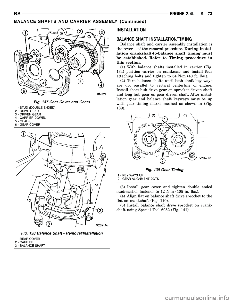
(1) With balance shafts installed in carrier (Fig.
134) position carrier on crankcase and install four
attaching bolts and tighten to 54 N´m (40 ft. lbs.).
(2) Turn balance shafts until both shaft key ways
are up, parallel to vertical centerline of engine.
Install short hub drive gear on sprocket driven shaft
and long hub gear on gear driven shaft. After instal-
lation gear and balance shaft keyways must be up
with gear timing marks meshed as shown in (Fig.
139).
(3) Install gear cover and tighten double ended
stud/washer fastener to 12 N´m (105 in. lbs.).
(4) Align flat on balance shaft drive sprocket to the
flat on crankshaft (Fig. 140).
(5) Install balance shaft drive sprocket on crank-
shaft using Special Tool 6052 (Fig. 141).
Fig. 137 Gear Cover and Gears
1 - STUD (DOUBLE ENDED)
2 - DRIVE GEAR
3 - DRIVEN GEAR
4 - CARRIER DOWEL
5 - GEAR(S)
6 - GEAR COVER
Fig. 138 Balance Shaft - Removal/Installation
1 - REAR COVER
2 - CARRIER
3 - BALANCE SHAFT
Fig. 139 Gear Timing
1 - KEY WAYS UP
2 - GEAR ALIGNMENT DOTS
RSENGINE 2.4L9-73
BALANCE SHAFTS AND CARRIER ASSEMBLY (Continued)
Page 1251 of 2339
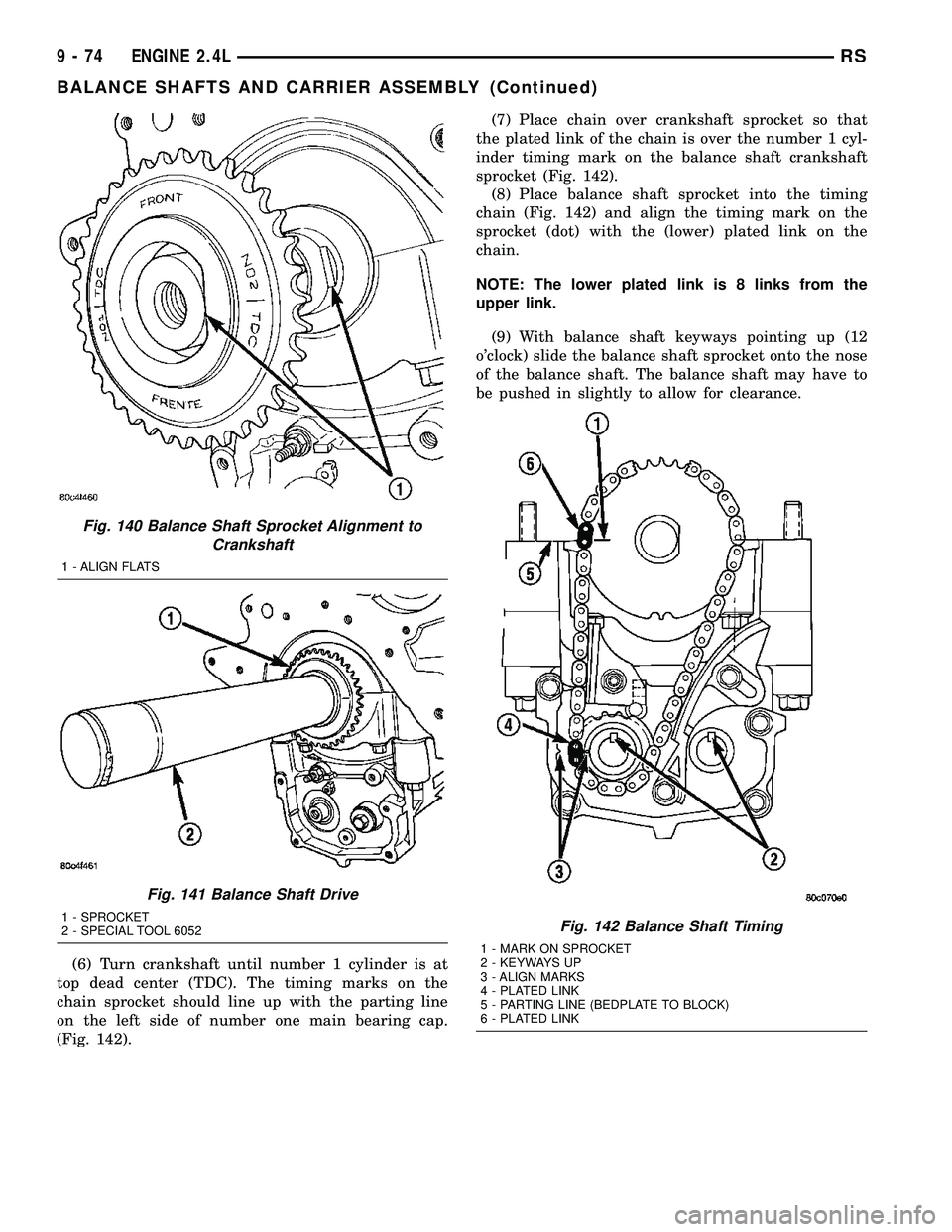
(6) Turn crankshaft until number 1 cylinder is at
top dead center (TDC). The timing marks on the
chain sprocket should line up with the parting line
on the left side of number one main bearing cap.
(Fig. 142).(7) Place chain over crankshaft sprocket so that
the plated link of the chain is over the number 1 cyl-
inder timing mark on the balance shaft crankshaft
sprocket (Fig. 142).
(8) Place balance shaft sprocket into the timing
chain (Fig. 142) and align the timing mark on the
sprocket (dot) with the (lower) plated link on the
chain.
NOTE: The lower plated link is 8 links from the
upper link.
(9) With balance shaft keyways pointing up (12
o'clock) slide the balance shaft sprocket onto the nose
of the balance shaft. The balance shaft may have to
be pushed in slightly to allow for clearance.
Fig. 140 Balance Shaft Sprocket Alignment to
Crankshaft
1 - ALIGN FLATS
Fig. 141 Balance Shaft Drive
1 - SPROCKET
2 - SPECIAL TOOL 6052Fig. 142 Balance Shaft Timing
1 - MARK ON SPROCKET
2 - KEYWAYS UP
3 - ALIGN MARKS
4 - PLATED LINK
5 - PARTING LINE (BEDPLATE TO BLOCK)
6 - PLATED LINK
9 - 74 ENGINE 2.4LRS
BALANCE SHAFTS AND CARRIER ASSEMBLY (Continued)
Page 1367 of 2339
FUEL DELIVERY
DESCRIPTION
DESCRIPTION
The front wheel drive car uses a plastic fuel tank
located rear center of the vehicle.
The Fuel Delivery System consists of: the following
items:
²Electric fuel pump module
²Fuel filter
²Tubes/lines/hoses
²Fuel injectors
The in-tank fuel pump module contains the fuel
pump. The pump is serviced as part of the fuel pump
module. Refer to Fuel Pump Module.
The fuel filter is replaceable only as part of the
fuel pump module.
DESCRIPTION - FFV REPLACEMENT PARTS
Many components in a Flexible Fuel Vehicle (FFV)
are designed to be compatible with ethanol. Always
be sure that the vehicle is serviced with correct etha-
nol compatible parts.
CAUTION: Replacing fuel system components with
non-ethanol compatible components can damage
your vehicle and may void the warranty.
OPERATION
The fuel system provides fuel pressure by an
in-tank pump module. The Powertrain Control Mod-
ule (PCM) controls the operation of the fuel system
by providing battery voltage to the fuel pump
through the fuel pump relay. The PCM requires only
three inputs and a good ground to operate the fuel
pump relay. The three inputs are:
²Ignition voltage
²Crankshaft Position (CKP) sensor
²Camshaft Position (CMP) sensor
DIAGNOSIS AND TESTING - FUEL DELIVERY
SYSTEM
(Refer to Appropriate Diagnostic Information)
STANDARD PROCEDURE
STANDARD PROCEDURE - FUEL SYSTEM
PRESSURE RELEASE PROCEDURE
(1) Remove Fuel Pump relay from Power Distribu-
tion Center (PDC). For location of relay, refer to label
on underside of PDC cover.
(2) Start and run engine until it stalls.(3) Attempt restarting engine until it will no
longer run.
(4) Turn ignition key to OFF position.
(5) Return fuel pump relay to PDC.
(6) One or more Diagnostic Trouble Codes (DTC's)
may have been stored in PCM memory due to fuel
pump relay removal. The DRB IIItscan tool must be
used to erase a DTC.
STANDARD PROCEDURE - DRAINING FUEL
TANK
Two different procedures may be used to drain fuel
tank (lowering tank or using DRBIIItscan tool).
The quickest draining procedure involves lowering
the fuel tank.
WARNING: RELEASE FUEL SYSTEM PRESSURE
BEFORE SERVICING FUEL SYSTEM COMPONENTS.
SERVICE VEHICLES IN WELL VENTILATED AREAS
AND AVOID IGNITION SOURCES. NEVER SMOKE
WHILE SERVICING THE VEHICLE. THIS MAY
RESULT IN PERSONAL INJURY OR DEATH.
As an alternative procedure, the electric fuel pump
may be activated allowing tank to be drained at fuel
rail connection. Refer to DRBIIItscan tool for fuel
pump activation procedures. Before disconnecting
fuel line at fuel rail, release fuel pressure. Refer to
the Fuel System Pressure Release Procedure in this
group for procedures. Disconnect the fuel line at the
fuel rail and remove the plastic retainer from the
fuel rail. Take plastic retainer and install it back into
the fuel line from body. Check the O-ring and make
sure that it is in place and not damaged. Attach end
of special test hose tool number 6539 at fuel line con-
nection from the body line. Position opposite end of
this hose tool to an approved gasoline draining sta-
tion. Activate fuel pump and drain tank until empty.
When done remove the special test hose tool number
6539 from the body line. Remove the plastic retainer
from the special test hose tool number 6539 and rein-
stall it into the fuel line from the body. Check the
O-ring and make sure that it is in place and not
damaged. Install the fuel line to the fuel rail.
If electric fuel pump is not operating, tank must be
lowered for fuel draining. Refer to following proce-
dures.
(1) Remove fuel filler cap.
(2) Perform the Fuel System Pressure Release pro-
cedure.
(3) Disconnect negative cable from battery.
(4) Raise vehicle and support.
(5) Certain models are equipped with a separate
grounding wire (strap) connecting the fuel fill tube
assembly to the body. Disconnect wire by removing
screw.
14 - 2 FUEL DELIVERYRS
Page 1387 of 2339
FUEL INJECTION
OPERATION
OPERATION - INJECTION SYSTEM
All engines used in this section have a sequential
Multi-Port Electronic Fuel Injection system. The MPI
system is computer regulated and provides precise
air/fuel ratios for all driving conditions. The Power-
train Control Module (PCM) operates the fuel injec-
tion system.
The PCM regulates:
²Ignition timing
²Air/fuel ratio
²Emission control devices
²Cooling fan
²Charging system
²Idle speed
²Vehicle speed control
Various sensors provide the inputs necessary for
the PCM to correctly operate these systems. In addi-
tion to the sensors, various switches also provide
inputs to the PCM.
The PCM can adapt its programming to meet
changing operating conditions.
Fuel is injected into the intake port above the
intake valve in precise metered amounts through
electrically operated injectors. The PCM fires the
injectors in a specific sequence. Under most operat-
ing conditions, the PCM maintains an air fuel ratio
of 14.7 parts air to 1 part fuel by constantly adjust-
ing injector pulse width. Injector pulse width is the
length of time the injector is open.
The PCM adjusts injector pulse width by opening
and closing the ground path to the injector. Engine
RPM (speed) and manifold absolute pressure (air
density) are theprimaryinputs that determine
injector pulse width.
OPERATION - MODES OF OPERATION
As input signals to the PCM change, the PCM
adjusts its response to output devices. For example,
the PCM must calculate a different injector pulse
width and ignition timing for idle than it does for
Wide Open Throttle (WOT). There are several differ-
ent modes of operation that determine how the PCM
responds to the various input signals.
There are two different areas of operation, OPEN
LOOP and CLOSED LOOP.
During OPEN LOOP modes the PCM receives
input signals and responds according to preset PCM
programming. Inputs from the upstream and down-
stream heated oxygen sensors are not monitored dur-
ing OPEN LOOP modes, except for heated oxygensensor diagnostics (they are checked for shorted con-
ditions at all times).
During CLOSED LOOP modes the PCM monitors
the inputs from the upstream and downstream
heated oxygen sensors. The upstream heated oxygen
sensor input tells the PCM if the calculated injector
pulse width resulted in the ideal air-fuel ratio of 14.7
to one. By monitoring the exhaust oxygen content
through the upstream heated oxygen sensor, the
PCM can fine tune injector pulse width. Fine tuning
injector pulse width allows the PCM to achieve opti-
mum fuel economy combined with low emissions.
For the PCM to enter CLOSED LOOP operation,
the following must occur:
(1) Engine coolant temperature must be over 35ÉF.
²If the coolant is over 35ÉF the PCM will wait 38
seconds.
²If the coolant is over 50ÉF the PCM will wait 15
seconds.
²If the coolant is over 167ÉF the PCM will wait 3
seconds.
(2) For other temperatures the PCM will interpo-
late the correct waiting time.
(3) O2 sensor must read either greater than 0.745
volts or less than 0.29 volt.
(4) The multi-port fuel injection systems has the
following modes of operation:
²Ignition switch ON (Zero RPM)
²Engine start-up
²Engine warm-up
²Cruise
²Idle
²Acceleration
²Deceleration
²Wide Open Throttle
²Ignition switch OFF
(5) The engine start-up (crank), engine warm-up,
deceleration with fuel shutoff and wide open throttle
modes are OPEN LOOP modes. Under most operat-
ing conditions, the acceleration, deceleration (with
A/C on), idle and cruise modes,with the engine at
operating temperatureare CLOSED LOOP modes.
IGNITION SWITCH ON (ZERO RPM) MODE
When the ignition switch activates the fuel injec-
tion system, the following actions occur:
²The PCM monitors the engine coolant tempera-
ture sensor and throttle position sensor input. The
PCM determines basic fuel injector pulse width from
this input.
²The PCM determines atmospheric air pressure
from the MAP sensor input to modify injector pulse
width.
When the key is in the ON position and the engine
is not running (zero rpm), the Auto Shutdown (ASD)
and fuel pump relays de-energize after approximately
14 - 22 FUEL INJECTIONRS
Page 1400 of 2339
Also like the cam and crank sensors, a 5 volt ref-
erence is supplied from the PCM and returns a volt-
age signal to the PCM that reflects manifold
pressure. The zero pressure reading is 0.5V and full
scale is 4.5V. For a pressure swing of0Ð15psithe
voltage changes 4.0V. The sensor is supplied a regu-
lated 4.8 to 5.1 volts to operate the sensor. Like the
cam and crank sensors ground is provided through
the sensor return circuit.
The MAP sensor input is the number one contrib-
utor to pulse width. The most important function of
the MAP sensor is to determine barometric pressure.
The PCM needs to know if the vehicle is at sea level
or is it in Denver at 5000 feet above sea level,
because the air density changes with altitude. It will
also help to correct for varying weather conditions. If
a hurricane was coming through the pressure would
be very, very low or there could be a real fair
weather, high pressure area. This is important
because as air pressure changes the barometric pres-
sure changes. Barometric pressure and altitude have
a direct inverse correlation, as altitude goes up baro-
metric goes down. The first thing that happens as
the key is rolled on, before reaching the crank posi-
tion, the PCM powers up, comes around and looks at
the MAP voltage, and based upon the voltage it sees,
it knows the current barometric pressure relative to
altitude. Once the engine starts, the PCM looks at
the voltage again, continuously every 12 milliseconds,
and compares the current voltage to what it was at
key on. The difference between current and what it
was at key on is manifold vacuum.
During key On (engine not running) the sensor
reads (updates) barometric pressure. A normal range
can be obtained by monitoring known good sensor in
you work area.As the altitude increases the air becomes thinner
(less oxygen). If a vehicle is started and driven to a
very different altitude than where it was at key On
the barometric pressure needs to be updated. Any
time the PCM sees Wide Open throttle, based upon
TPS angle and RPM it will update barometric pres-
sure in the MAP memory cell. With periodic updates,
the PCM can make its calculations more effectively.
The PCM uses the MAP sensor to aid in calculat-
ing the following:
²Barometric pressure
²Engine load
²Manifold pressure
²Injector pulse-width
²Spark-advance programs
²Shift-point strategies (F4AC1 transmissions
only, via the PCI bus)
²Idle speed
²Decel fuel shutoff
The PCM recognizes a decrease in manifold pres-
sure by monitoring a decrease in voltage from the
reading stored in the barometric pressure memory
cell. The MAP sensor is a linear sensor; as pressure
changes, voltage changes proportionately. The range
of voltage output from the sensor is usually between
4.6 volts at sea level to as low as 0.3 volts at 26 in. of
Hg. Barometric pressure is the pressure exerted by
the atmosphere upon an object. At sea level on a
standard day, no storm, barometric pressure is 29.92
in Hg. For every 100 feet of altitude barometric pres-
sure drops .10 in. Hg. If a storm goes through it can
either add, high pressure, or decrease, low pressure,
from what should be present for that altitude. You
should make a habit of knowing what the average
pressure and corresponding barometric pressure is
for your area.
REMOVAL
REMOVAL - 2.4L
(1) Disconnect the negative battery cable.
(2) Disconnect electrical connector and vacuum
hose from MAP sensor (Fig. 20).
(3) Remove two screws holding sensor to the
intake manifold.
REMOVAL - 3.3/3.8L
(1) Disconnect the negative battery cable.
(2) Remove vacuum hose and mounting screws
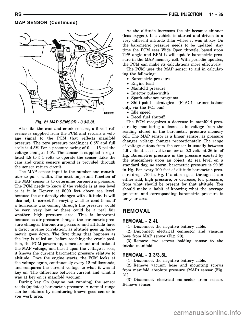
from manifold absolute pressure (MAP) sensor (Fig.
21).
(3) Disconnect electrical connector from sensor.
Remove sensor.
Fig. 21 MAP SENSOR - 3.3/3.8L
RSFUEL INJECTION14-35
MAP SENSOR (Continued)
Page 1417 of 2339
COLUMN
TABLE OF CONTENTS
page page
COLUMN
DESCRIPTION - STEERING COLUMN.......10
WARNING
WARNINGS AND CAUTIONS.............10
DIAGNOSIS AND TESTING - STEERING
COLUMN............................11
REMOVAL.............................11
INSTALLATION.........................16
SPECIFICATIONS
COLUMN FASTENER TORQUE...........17
IGNITION SWITCH
REMOVAL.............................17
INSTALLATION.........................19
KEY/LOCK CYLINDER
DESCRIPTION.........................20OPERATION...........................20
REMOVAL.............................20
INSTALLATION.........................20
SHROUD - LOWER
REMOVAL.............................21
INSTALLATION.........................21
SHROUD - UPPER
REMOVAL.............................22
INSTALLATION.........................22
STEERING WHEEL
REMOVAL.............................23
INSTALLATION.........................24
COLUMN
DESCRIPTION - STEERING COLUMN
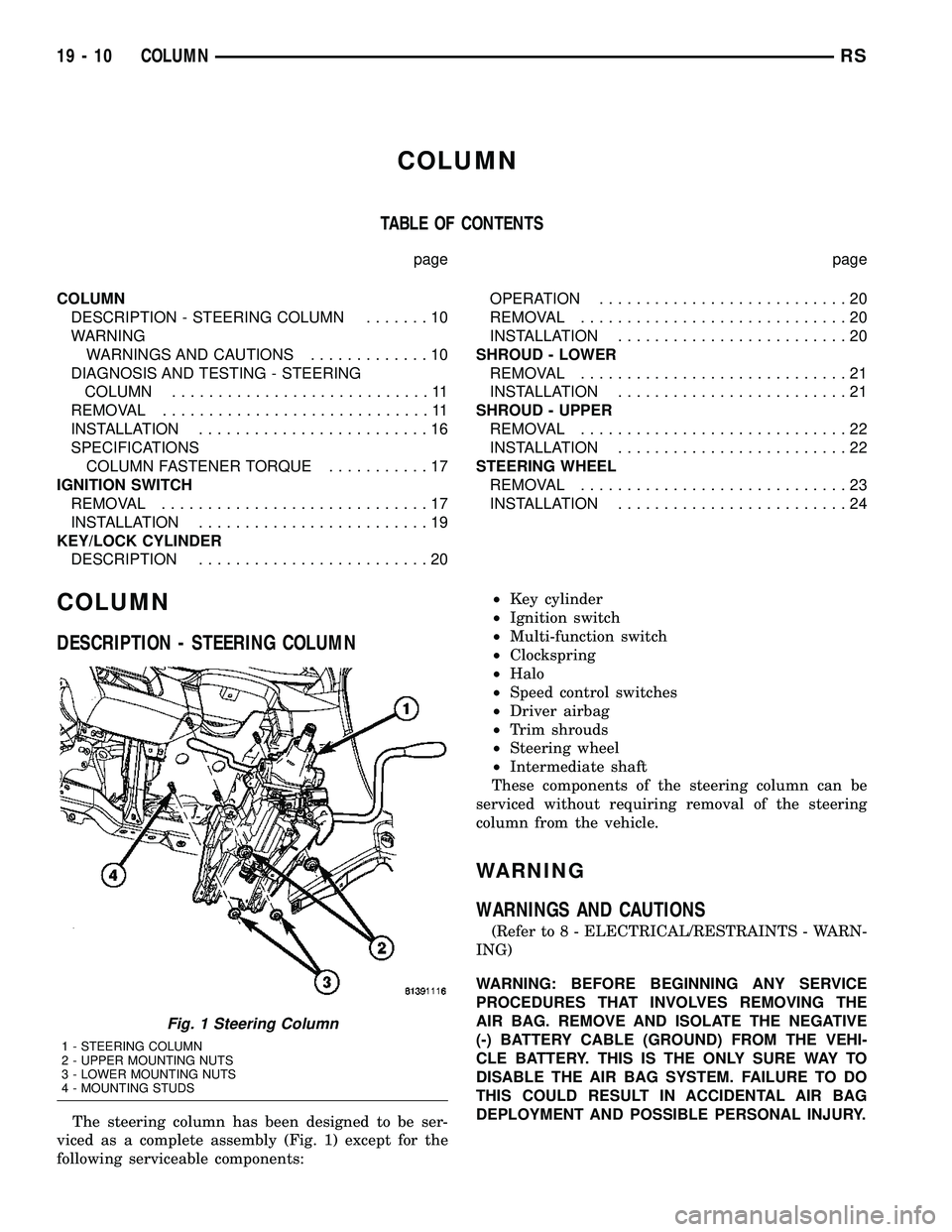
The steering column has been designed to be ser-
viced as a complete assembly (Fig. 1) except for the
following serviceable components:²Key cylinder
²Ignition switch
²Multi-function switch
²Clockspring
²Halo
²Speed control switches
²Driver airbag
²Trim shrouds
²Steering wheel
²Intermediate shaft
These components of the steering column can be
serviced without requiring removal of the steering
column from the vehicle.
WARNING
WARNINGS AND CAUTIONS
(Refer to 8 - ELECTRICAL/RESTRAINTS - WARN-
ING)
WARNING: BEFORE BEGINNING ANY SERVICE
PROCEDURES THAT INVOLVES REMOVING THE
AIR BAG. REMOVE AND ISOLATE THE NEGATIVE
(-) BATTERY CABLE (GROUND) FROM THE VEHI-
CLE BATTERY. THIS IS THE ONLY SURE WAY TO
DISABLE THE AIR BAG SYSTEM. FAILURE TO DO
THIS COULD RESULT IN ACCIDENTAL AIR BAG
DEPLOYMENT AND POSSIBLE PERSONAL INJURY.
Fig. 1 Steering Column
1 - STEERING COLUMN
2 - UPPER MOUNTING NUTS
3 - LOWER MOUNTING NUTS
4 - MOUNTING STUDS
19 - 10 COLUMNRS