2005 CHRYSLER VOYAGER ail
[x] Cancel search: ailPage 2280 of 2339
The information obtained by the sensor is used to
calculate the fuel injector pulse width. The PCM is
programmed to maintain the optimum air/fuel ratio.
At this mixture ratio, the catalyst works best to
remove hydrocarbons (HC), carbon monoxide (CO)
and nitrous oxide (NOx) from the exhaust.
The O2S is also the main sensing element for the
EGR (if equipped), Catalyst and Fuel Monitors.
The O2S may fail in any or all of the following
manners:
²Slow response rate
²Reduced output voltage
²Dynamic shift
²Shorted or open circuits
Response rate is the time required for the sensor to
switch from lean to rich once it is exposed to a richer
than optimum A/F mixture or vice versa. As the sen-
sor starts malfunctioning, it could take longer to
detect the changes in the oxygen content of the
exhaust gas.
The output voltage of the O2S ranges from 0 to 1
volt (voltages are offset by 2.5 volts on NGC vehi-
cles). A good sensor can easily generate any output
voltage in this range as it is exposed to different con-
centrations of oxygen. To detect a shift in the A/F
mixture (lean or rich), the output voltage has to
change beyond a threshold value. A malfunctioning
sensor could have difficulty changing beyond the
threshold value.
OXYGEN SENSOR HEATER MONITOR
If there is an oxygen sensor (O2S) DTC as well as
a O2S heater DTC, the O2S heater fault MUST be
repaired first. After the O2S fault is repaired, verify
that the heater circuit is operating correctly.
Effective control of exhaust emissions is achieved
by an oxygen feedback system. The most important
element of the feedback system is the O2S. The O2S
is located in the exhaust path. Once it reaches oper-
ating temperatures of 300É to 350ÉC (572 É to 662ÉF),
the sensor generates a voltage that is inversely pro-
portional to the amount of oxygen in the exhaust.
The information obtained by the sensor is used to
calculate the fuel injector pulse width. This main-
tains a 14.7 to 1 Air Fuel (A/F) ratio. At this mixture
ratio, the catalyst works best to remove hydrocarbons
(HC), carbon monoxide (CO) and nitrogen oxide
(NOx) from the exhaust.
The voltage readings taken from the O2S are very
temperature sensitive. The readings are not accurate
below 300ÉC. Heating of the O2S is done to allow the
engine controller to shift to closed loop control as
soon as possible. The heating element used to heat
the O2S must be tested to ensure that it is heating
the sensor properly.The O2S circuit is monitored for a drop in voltage.
The sensor output is used to test the heater by iso-
lating the effect of the heater element on the O2S
output voltage from the other effects.
EGR MONITOR (if equipped)
The Powertrain Control Module (PCM) performs
an on-board diagnostic check of the EGR system.
The EGR monitor is used to test whether the EGR
system is operating within specifications. The diag-
nostic check activates only during selected engine/
driving conditions. When the conditions are met, the
EGR is turned off (solenoid energized) and the O2S
compensation control is monitored. Turning off the
EGR shifts the air fuel (A/F) ratio in the lean direc-
tion. The O2S data should indicate an increase in the
O2 concentration in the combustion chamber when
the exhaust gases are no longer recirculated. While
this test does not directly measure the operation of
the EGR system, it can be inferred from the shift in
the O2S data whether the EGR system is operating
correctly. Because the O2S is being used, the O2S
test must pass its test before the EGR test. Also
looks at EGR linear potentiometer for feedback.
MISFIRE MONITOR
Excessive engine misfire results in increased cata-
lyst temperature and causes an increase in HC emis-
sions. Severe misfires could cause catalyst damage.
To prevent catalytic convertor damage, the PCM
monitors engine misfire.
The Powertrain Control Module (PCM) monitors
for misfire during most engine operating conditions
(positive torque) by looking at changes in the crank-
shaft speed. If a misfire occurs the speed of the
crankshaft will vary more than normal.
FUEL SYSTEM MONITOR
To comply with clean air regulations, vehicles are
equipped with catalytic converters. These converters
reduce the emission of hydrocarbons, oxides of nitro-
gen and carbon monoxide. The catalyst works best
when the air fuel (A/F) ratio is at or near the opti-
mum of 14.7 to 1.
The PCM is programmed to maintain the optimum
air/fuel ratio. This is done by making short term cor-
rections in the fuel injector pulse width based on the
O2S output. The programmed memory acts as a self
calibration tool that the engine controller uses to
compensate for variations in engine specifications,
sensor tolerances and engine fatigue over the life
span of the engine. By monitoring the actual air-fuel
ratio with the O2S (short term) and multiplying that
with the program long-term (adaptive) memory and
comparing that to the limit, it can be determined
whether it will pass an emissions test. If a malfunc-
RSEMISSIONS CONTROL25-7
EMISSIONS CONTROL (Continued)
Page 2281 of 2339
tion occurs such that the PCM cannot maintain the
optimum A/F ratio, then the MIL will be illuminated.
CATALYST MONITOR
To comply with clean air regulations, vehicles are
equipped with catalytic converters. These converters
reduce the emission of hydrocarbons, oxides of nitro-
gen and carbon monoxide.
Normal vehicle miles or engine misfire can cause a
catalyst to decay. A meltdown of the ceramic core can
cause a reduction of the exhaust passage. This can
increase vehicle emissions and deteriorate engine
performance, driveability and fuel economy.
The catalyst monitor uses dual oxygen sensors
(O2S's) to monitor the efficiency of the converter. The
dual O2S's strategy is based on the fact that as a cat-
alyst deteriorates, its oxygen storage capacity and its
efficiency are both reduced. By monitoring the oxy-
gen storage capacity of a catalyst, its efficiency can
be indirectly calculated. The upstream O2S is used to
detect the amount of oxygen in the exhaust gas
before the gas enters the catalytic converter. The
PCM calculates the A/F mixture from the output of
the O2S. A low voltage indicates high oxygen content
(lean mixture). A high voltage indicates a low content
of oxygen (rich mixture).
When the upstream O2S detects a lean condition,
there is an abundance of oxygen in the exhaust gas.
A functioning converter would store this oxygen so it
can use it for the oxidation of HC and CO. As the
converter absorbs the oxygen, there will be a lack of
oxygen downstream of the converter. The output of
the downstream O2S will indicate limited activity in
this condition.
As the converter loses the ability to store oxygen,
the condition can be detected from the behavior of
the downstream O2S. When the efficiency drops, no
chemical reaction takes place. This means the con-
centration of oxygen will be the same downstream as
upstream. The output voltage of the downstream
O2S copies the voltage of the upstream sensor. The
only difference is a time lag (seen by the PCM)
between the switching of the O2S's.
To monitor the system, the number of lean-to-rich
switches of upstream and downstream O2S's is
counted. The ratio of downstream switches to
upstream switches is used to determine whether the
catalyst is operating properly. An effective catalyst
will have fewer downstream switches than it has
upstream switches i.e., a ratio closer to zero. For a
totally ineffective catalyst, this ratio will be one-to-
one, indicating that no oxidation occurs in the device.
The system must be monitored so that when cata-
lyst efficiency deteriorates and exhaust emissions
increase to over the legal limit, the MIL (Check
Engine lamp) will be illuminated.NATURAL VACUUM LEAK DETECTION (NVLD) (if equipped)
The Natural Vacuum Leak Detection (NVLD) sys-
tem is the next generation evaporative leak detection
system that will first be used on vehicles equipped
with the Next Generation Controller (NGC). This
new system replaces the leak detection pump as the
method of evaporative system leak detection. This is
to detect a leak equivalent to a 0.0209(0.5 mm) hole.
This system has the capability to detect holes of this
size very dependably.
The basic leak detection theory employed with
NVLD is the9Gas Law9. This is to say that the pres-
sure in a sealed vessel will change if the temperature
of the gas in the vessel changes. The vessel will only
see this effect if it is indeed sealed. Even small leaks
will allow the pressure in the vessel to come to equi-
librium with the ambient pressure. In addition to the
detection of very small leaks, this system has the
capability of detecting medium as well as large evap-
orative system leaks.
The NVLD seals the canister vent during engine
off conditions. If the EVAP system has a leak of less
than the failure threshold, the evaporative system
will be pulled into a vacuum, either due to the cool
down from operating temperature or diurnal ambient
temperature cycling. The diurnal effect is considered
one of the primary contributors to the leak determi-
nation by this diagnostic. When the vacuum in the
system exceeds about 19H2O (0.25 KPA), a vacuum
switch closes. The switch closure sends a signal to
the NGC. The NGC, via appropriate logic strategies
(described below), utilizes the switch signal, or lack
thereof, to make a determination of whether a leak is
present.
The NVLD device is designed with a normally open
vacuum switch, a normally closed solenoid, and a
seal, which is actuated by both the solenoid and a
diaphragm. The NVLD is located on the atmospheric
vent side of the canister. The NVLD assembly may
be mounted on top of the canister outlet, or in-line
between the canister and atmospheric vent filter. The
normally open vacuum switch will close with about 19
H2O (0.25 KPA) vacuum in the evaporative system.
The diaphragm actuates the switch. This is above the
opening point of the fuel inlet check valve in the fill
tube so cap off leaks can be detected. Submerged fill
systems must have recirculation lines that do not
have the in-line normally closed check valve that pro-
tects the system from failed nozzle liquid ingestion,
in order to detect cap off conditions.
The normally closed valve in the NVLD is intended
to maintain the seal on the evaporative system dur-
ing the engine off condition. If vacuum in the evapo-
rative system exceeds 39to 69H2O (0.75 to 1.5 KPA),
the valve will be pulled off the seat, opening the seal.
This will protect the system from excessive vacuum
25 - 8 EMISSIONS CONTROLRS
EMISSIONS CONTROL (Continued)
Page 2288 of 2339
LEAK DETECTION PUMP
REMOVAL
(1) Disconnect the negative battery cable.
(2) Raise and support the vehicle.
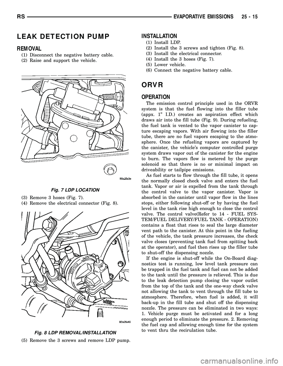
(3) Remove 3 hoses (Fig. 7).
(4) Remove the electrical connector (Fig. 8).
(5) Remove the 3 screws and remove LDP pump.
INSTALLATION
(1) Install LDP.
(2) Install the 3 screws and tighten (Fig. 8).
(3) Install the electrical connector.
(4) Install the 3 hoses (Fig. 7).
(5) Lower vehicle.
(6) Connect the negative battery cable.
ORVR
OPERATION
The emission control principle used in the ORVR
system is that the fuel flowing into the filler tube
(appx. 1º I.D.) creates an aspiration effect which
draws air into the fill tube (Fig. 9). During refueling,
the fuel tank is vented to the vapor canister to cap-
ture escaping vapors. With air flowing into the filler
tube, there are no fuel vapors escaping to the atmo-
sphere. Once the refueling vapors are captured by
the canister, the vehicle's computer controlled purge
system draws vapor out of the canister for the engine
to burn. The vapors flow is metered by the purge
solenoid so that there is no or minimal impact on
driveability or tailpipe emissions.
As fuel starts to flow through the fill tube, it opens
the normally closed check valve and enters the fuel
tank. Vapor or air is expelled from the tank through
the control valve to the vapor canister. Vapor is
absorbed in the canister until vapor flow in the lines
stops, either following shut-off or by having the fuel
level in the tank rise high enough to close the control
valve. The control valve(Refer to 14 - FUEL SYS-
TEM/FUEL DELIVERY/FUEL TANK - OPERATION)
contains a float that rises to seal the large diameter
vent path to the canister. At this point in the fueling
of the vehicle, the tank pressure increases, the check
valve closes (preventing tank fuel from spitting back
at the operator), and fuel then rises up the filler tube
to shut-off the dispensing nozzle.
If the engine is shut-off while the On-Board diag-
nostics test is running, low level tank pressure can
be trapped in the fuel tank and fuel can not be added
to the tank until the pressure is relieved. This is due
to the leak detection pump closing the vapor outlet
from the top of the tank and the one-way check valve
not allowing the tank to vent through the fill tube to
atmosphere. Therefore, when fuel is added, it will
back-up in the fill tube and shut off the dispensing
nozzle. The pressure can be eliminated in two ways:
1. Vehicle purge must be activated and for a long
enough period to eliminate the pressure. 2. Removing
the fuel cap and allowing enough time for the system
to vent thru the recirulation tube.
Fig. 7 LDP LOCATION
Fig. 8 LDP REMOVAL/INSTALLATION
RSEVAPORATIVE EMISSIONS25-15
Page 2290 of 2339
DIAGNOSIS AND TESTING - VEHICLE DOES
NOT FILL
CONDITION POSSIBLE CAUSES CORRECTION
Pre-Mature Nozzle Shut-Off Defective fuel tank assembly
components.Fill tube improperly installed
(sump)
Fill tube hose pinched.
Check valve stuck shut.
Control valve stuck shut.
Defective vapor/vent components. Vent line from control valve to
canister pinched.
Vent line from canister to vent
filter pinched.
Canister vent valve failure
(requires double failure,
plugged to NVLD and
atmosphere).
Leak detection pump failed
closed.
Leak detection pump filter
plugged.
On-Board diagnostics evaporative
system leak test just conducted.Canister vent valve vent
plugged to atmosphere.
Engine still running when
attempting to fill (System
designed not to fill).
Defective fill nozzle. Try another nozzle.
Fuel Spits Out Of Filler
Tube.During fill. See Pre-Mature Shut-Off.
At conclusion of fill. Defective fuel handling
component. (Check valve stuck
open).
Defective vapor/vent handling
component.
Defective fill nozzle.
RSEVAPORATIVE EMISSIONS25-17
ORVR (Continued)
Page 2297 of 2339
De-energizing the solenoid, but not fully closing the
transducer bleed hole (because of low back-pressure),
varies the strength of vacuum applied to the EGR
valve. Varying the strength of the vacuum changes
the amount of EGR supplied to the engine. This pro-
vides the correct amount of exhaust gas recirculation
for different operating conditions.
This system does not allow EGR at idle.
A failed or malfunctioning EGR system can cause
engine spark knock, sags or hesitation, rough idle,
engine stalling and increased emissions.
REMOVAL - 2.4L
The EGR valve and Electrical EGR Transducer are
serviced as an assembly (Fig. 1).
(1) Disconnect vacuum tube from electric EGR
transducer. Inspect vacuum tube for damage.
(2) Remove electrical connector from solenoid.
(3) Remove EGR tube bolts from EGR valve.
(4) Remove EGR valve from cylinder head adaptor.(5) Clean gasket surface and discard old gasket.
Check for any signs of leakage or cracked surfaces.
Repair or replace as necessary.
INSTALLATION - 2.4L
The EGR valve and Electrical EGR Transducer are
serviced as an assembly (Fig. 1).
(1) Assemble EGR valve with new gasket onto the
cylinder head adaptor.
(2) Loose assemble the bolts from EGR valve to
EGR tube.
(3) Loose assemble the bolts from EGR valve to
cylinder head.
(4) Tighten bolts from EGR valve to cylinder head
to 22.8 N´m (200 25 in. lbs.) torque.
(5) Tighten bolts from EGR valve to EGR tube to
11.9 N´m (105 20 in. lbs.) torque.
(6) Reconnect vacuum hose and electrical connec-
tor to electrical EGR transducer.
25 - 24 EXHAUST GAS RECIRCULATIONRS
VALVE (Continued)
Page 2298 of 2339
ON-BOARD DIAGNOSTICS
TABLE OF CONTENTS
page page
TASK MANAGER
DESCRIPTION.........................25OPERATION...........................25
TASK MANAGER
DESCRIPTION
The PCM is responsible for efficiently coordinating
the operation of all the emissions-related compo-
nents. The PCM is also responsible for determining if
the diagnostic systems are operating properly. The
software designed to carry out these responsibilities
is call the ªTask Managerº.
OPERATION
The Task Manager determines when tests happen
and when functions occur. Many of the diagnostic
steps required by OBD II must be performed under
specific operating conditions. The Task Manager soft-
ware organizes and prioritizes the diagnostic proce-
dures. The job of the Task Manager is to determine if
conditions are appropriate for tests to be run, moni-
tor the parameters for a trip for each test, and record
the results of the test. Following are the responsibil-
ities of the Task Manager software:
²Test Sequence
²MIL Illumination
²Diagnostic Trouble Codes (DTCs)
²Trip Indicator
²Freeze Frame Data Storage
²Similar Conditions Window
Test Sequence
In many instances, emissions systems must fail
diagnostic tests more than once before the PCM illu-
minates the MIL. These tests are known as 'two trip
monitors.' Other tests that turn the MIL lamp on
after a single failure are known as 'one trip moni-
tors.' A trip is defined as 'start the vehicle and oper-
ate it to meet the criteria necessary to run the given
monitor.'
Many of the diagnostic tests must be performed
under certain operating conditions. However, there
are times when tests cannot be run because another
test is in progress (conflict), another test has failed
(pending) or the Task Manager has set a fault that
may cause a failure of the test (suspend).
²Pending
Under some situations the Task Manager will notrun a monitor if the MIL is illuminated and a fault is
stored from another monitor. In these situations, the
Task Manager postpones monitorspendingresolu-
tion of the original fault. The Task Manager does not
run the test until the problem is remedied.
For example, when the MIL is illuminated for an
Oxygen Sensor fault, the Task Manager does not run
the Catalyst Monitor until the Oxygen Sensor fault is
remedied. Since the Catalyst Monitor is based on sig-
nals from the Oxygen Sensor, running the test would
produce inaccurate results.
²Conflict
There are situations when the Task Manager does
not run a test if another monitor is in progress. In
these situations, the effects of another monitor run-
ning could result in an erroneous failure. If thiscon-
flictis present, the monitor is not run until the
conflicting condition passes. Most likely the monitor
will run later after the conflicting monitor has
passed.
For example, if the Fuel System Monitor is in
progress, the Task Manager does not run the catalyst
Monitor. Since both tests monitor changes in air/fuel
ratio and adaptive fuel compensation, the monitors
will conflict with each other.
²Suspend
Occasionally the Task Manager may not allow a two
trip fault to mature. The Task Manager willsus-
pendthe maturing of a fault if a condition exists
that may induce an erroneous failure. This prevents
illuminating the MIL for the wrong fault and allows
more precise diagnosis.
For example, if the PCM is storing a one trip fault
for the Oxygen Sensor and the catalyst monitor, the
Task Manager may still run the catalyst Monitor but
will suspend the results until the Oxygen Sensor
Monitor either passes or fails. At that point the Task
Manager can determine if the catalyst system is
actually failing or if an Oxygen Sensor is failing.
MIL Illumination
The PCM Task Manager carries out the illumina-
tion of the MIL. The Task Manager triggers MIL illu-
mination upon test failure, depending on monitor
failure criteria.
RSON-BOARD DIAGNOSTICS25-25
Page 2299 of 2339
The Task Manager Screen shows both a Requested
MIL state and an Actual MIL state. When the MIL is
illuminated upon completion of a test for a good trip,
the Requested MIL state changes to OFF. However,
the MIL remains illuminated until the next key
cycle. (On some vehicles, the MIL will actually turn
OFF during the thirdgood trip) During the key cycle
for the third good trip, the Requested MIL state is
OFF, while the Actual MIL state is ON. After the
next key cycle, the MIL is not illuminated and both
MIL states read OFF.
Diagnostic Trouble Codes (DTCs)
With OBD II, different DTC faults have different
priorities according to regulations. As a result, the
priorities determine MIL illumination and DTC era-
sure. DTCs are entered according to individual prior-
ity. DTCs with a higher priority overwrite lower
priority DTCs.
Priorities
²Priority 0 ÐNon-emissions related trouble codes.
²Priority 1 Ð One trip failure of a two trip fault
for non-fuel system and non-misfire. (MIL Off)
²Priority 2 Ð One trip failure of a two trip fault
for fuel system (rich/lean) or misfire. (MIL Off)
²Priority3ÐTwotrip failure for a non-fuel sys-
tem and non-misfire or matured one trip comprehen-
sive component fault. (MIL On)
²Priority4ÐTwotrip failure or matured fault
for fuel system (rich/lean) and misfire or one trip cat-
alyst damaging misfire. Catalyst damage misfire is a
2 trip MIL. The MIL flashes on the first trip when
catalyst damage misfire levels are present. (MIL On)
Non-emissions related failures have no priority.
One trip failures of two trip faults have low priority.
Two trip failures or matured faults have higher pri-
ority. One and two trip failures of fuel system and
misfire monitor take precedence over non-fuel system
and non-misfire failures.
DTC Self Erasure
With one trip components or systems, the MIL is
illuminated upon test failure and DTCs are stored.
Two trip monitors are components requiring failure
in two consecutive trips for MIL illumination. Upon
failure of the first test, the Task Manager enters a
maturing code. If the component fails the test for a
second time the code matures and a DTC is set.
After three good trips the MIL is extinguished and
the Task Manager automatically switches the trip
counter to a warm-up cycle counter. DTCs are auto-
matically erased following 40 warm-up cycles if the
component does not fail again.
For misfire and fuel system monitors, the compo-
nent must pass the test under a Similar Conditions
Window in order to record a good trip. A Similar Con-ditions Window is when engine RPM is within 375
RPM and load is within 20% of when the fault
occurred.
NOTE: It is important to understand that a compo-
nent does not have to fail under a similar window of
operation to mature. It must pass the test under a
Similar Conditions Window when it failed to record
a Good Trip for DTC erasure for misfire and fuel
system monitors.
DTCs can be erased anytime with a scan tool.
Erasing the DTC with the scan tool erases all OBD
II information. The scan tool automatically displays a
warning that erasing the DTC will also erase all
OBD II monitor data. This includes all counter infor-
mation for warm-up cycles, trips and Freeze Frame.
Trip Indicator
TheTripis essential for running monitors and
extinguishing the MIL. In OBD II terms, a trip is a
set of vehicle operating conditions that must be met
for a specific monitor to run. All trips begin with a
key cycle.
Good Trip
The Good Trip counters are as follows:
²Global Good Trip
²Fuel System Good Trip
²Misfire Good Trip
²Alternate Good Trip (appears as a Global Good
Trip on scan tool)
²Comprehensive Components
²Major Monitor
²Warm-Up Cycles
Global Good Trip
To increment a Global Good Trip, the Oxygen sen-
sor and Catalyst efficiency monitors must have run
and passed, and 2 minutes of engine run time.
Fuel System Good Trip
To count a good trip (three required) and turn off
the MIL, the following conditions must occur:
²Engine in closed loop
²Operating in Similar Conditions Window
²Short Term multiplied by Long Term less than
threshold
²Less than threshold for a predetermined time
If all of the previous criteria are met, the PCM will
count a good trip (three required) and turn off the
MIL.
Misfire Good Trip
If the following conditions are met the PCM will
count one good trip (three required) in order to turn
off the MIL:
²Operating in Similar Condition Window
²1000 engine revolutions with no misfire
25 - 26 ON-BOARD DIAGNOSTICSRS
TASK MANAGER (Continued)
Page 2300 of 2339
Alternate Good Trip
Alternate Good Trips are used in place of Global
Good Trips for Comprehensive Components and
Major Monitors. If the Task Manager cannot run a
Global Good Trip because a component fault is stop-
ping the monitor from running, it will attempt to
count an Alternate Good Trip.
The Task Manager counts an Alternate Good Trip
for Comprehensive components when the following
conditions are met:
²Two minutes of engine run time, idle or driving
²No other faults occur
The Task Manager counts an Alternate Good Trip
for a Major Monitor when the monitor runs and
passes. Only the Major Monitor that failed needs to
pass to count an Alternate Good Trip.
Warm-Up Cycles
Once the MIL has been extinguished by the Good
Trip Counter, the PCM automatically switches to a
Warm-Up Cycle Counter that can be viewed on the
scan tool. Warm-Up Cycles are used to erase DTCs
and Freeze Frames. Forty Warm-Up cycles must
occur in order for the PCM to self-erase a DTC and
Freeze Frame. A Warm-Up Cycle is defined as fol-
lows:
²Engine coolant temperature must start below
and rise above 160É F
²Engine coolant temperature must rise by 40É F
²No further faults occur
Freeze Frame Data Storage
Once a failure occurs, the Task Manager records
several engine operating conditions and stores it in a
Freeze Frame. The Freeze Frame is considered one
frame of information taken by an on-board data
recorder. When a fault occurs, the PCM stores the
input data from various sensors so that technicians
can determine under what vehicle operating condi-
tions the failure occurred.
The data stored in Freeze Frame is usually
recorded when a system fails the first time for two
trip faults. Freeze Frame data will only be overwrit-
ten by a different fault with a higher priority.
CAUTION: Erasing DTCs, either with the scan tool;
or by disconnecting the battery, also clears all
Freeze Frame data.
Similar Conditions Window
The Similar Conditions Window displays informa-
tion about engine operation during a monitor. Abso-
lute MAP (engine load) and Engine RPM are stored
in this window when a failure occurs. There are two
different Similar conditions Windows: Fuel System
and Misfire.FUEL SYSTEM
²Fuel System Similar Conditions WindowÐ
An indicator that 'Absolute MAP When Fuel Sys Fail'
and 'RPM When Fuel Sys Failed' are all in the same
range when the failure occurred. Indicated by switch-
ing from 'NO' to 'YES'.
²Absolute MAP When Fuel Sys FailÐ The
stored MAP reading at the time of failure. Informs
the user at what engine load the failure occurred.
²Absolute MAPÐ A live reading of engine load
to aid the user in accessing the Similar Conditions
Window.
²RPM When Fuel Sys FailÐ The stored RPM
reading at the time of failure. Informs the user at
what engine RPM the failure occurred.
²Engine RPMÐ A live reading of engine RPM
to aid the user in accessing the Similar Conditions
Window.
²Adaptive Memory FactorÐ The PCM utilizes
both Short Term Compensation and Long Term Adap-
tive to calculate the Adaptive Memory Factor for
total fuel correction.
²Upstream O2S VoltsÐ A live reading of the
Oxygen Sensor to indicate its performance. For
example, stuck lean, stuck rich, etc.
²SCW Time in Window (Similar Conditions
Window Time in Window)Ð A timer used by the
PCM that indicates that, after all Similar Conditions
have been met, if there has been enough good engine
running time in the SCW without failure detected.
This timer is used to increment a Good Trip.
²Fuel System Good Trip CounterÐATrip
Counter used to turn OFF the MIL for Fuel System
DTCs. To increment a Fuel System Good Trip, the
engine must be in the Similar Conditions Window,
Adaptive Memory Factor must be less than cali-
brated threshold and the Adaptive Memory Factor
must stay below that threshold for a calibrated
amount of time.
²Test Done This TripÐ Indicates that the
monitor has already been run and completed during
the current trip.
MISFIRE
²Same Misfire Warm-Up StateÐ Indicates if
the misfire occurred when the engine was warmed up
(above 160É F).
²In Similar Misfire WindowÐ An indicator
that 'Absolute MAP When Misfire Occurred' and
'RPM When Misfire Occurred' are all in the same
range when the failure occurred. Indicated by switch-
ing from 'NO' to 'YES'.
²Absolute MAP When Misfire OccurredÐ
The stored MAP reading at the time of failure.
Informs the user at what engine load the failure
occurred.
RSON-BOARD DIAGNOSTICS25-27
TASK MANAGER (Continued)