2005 CHRYSLER VOYAGER Module
[x] Cancel search: ModulePage 2248 of 2339
(18) Disconnect the suction line extension fitting
from the underbody suction line fitting for the rear
air conditioner.
(19) Remove the O-ring seal from the underbody
suction line fitting and discard.
(20) Install plugs in, or tape over the opened suc-
tion line fittings.
(21) Lower the vehicle.
(22) Remove the suction line from the engine com-
partment.
INSTALLATION
(1) Position the suction line into the engine com-
partment.
(2) Remove the tape or plugs from the suction line
and liquid line fittings and both expansion valve
ports.
(3) Lubricate new rubber O-ring seals with clean
refrigerant oil and install them on the suction line
and liquid line fittings.
(4) Reconnect the liquid line and suction line fit-
tings to the expansion valve.
(5) Install the nut that secures the suction line
and liquid line fittings to the expansion valve.
Tighten the nut to 23 N´m (17 ft. lbs.).
(6) Install the retainer that secures the suction
line routing clip to the receiver/drier mounting
bracket on the side of the right front strut tower in
the engine compartment.(7) Remove the tape or plugs from the compressor
suction port and the suction line fitting.
(8) Lubricate a new rubber O-ring seal with clean
refrigerant oil and install it on the suction line fit-
ting.
(9) Install a new dual plan seal and reconnect the
suction line fitting to the compressor suction port.
(10) Install the nut that secures the suction line
fitting to the A/C compressor. Tighten the nut to 23
N´m (17 ft. lbs.).
(11) Reconnect the drain tube to the wiper module
drain on the right side of the engine compartment.
(12) Install the air cleaner top cover and snorkel
onto the air cleaner housing located on the right side
of the engine compartment.
(13) On RHD models, install the suction line into
the retaining bracket located at the top of the dash
panel.
(14) If the vehicle is equipped with the optional
rear air conditioner, go to Step 15. If the vehicle does
not have the optional rear air conditioner, go to Step
21.
(15) Raise and support the vehicle.
(16) Remove the tape or plugs from the suction
line extension fitting and the underbody suction line
fitting.
(17) Lubricate a new rubber O-ring seal with clean
refrigerant oil and install it on the underbody suction
line fitting.
(18) Reconnect the suction line extension fitting to
the underbody suction line fitting. Tighten the fit-
tings to 23 N´m (17 ft. lbs.).
(19) Install a new tie strap just forward of the con-
nections between the underbody plumbing and the
engine compartment plumbing for the rear heater
and air conditioner.
(20) Lower the vehicle.
(21) Reconnect the battery negative cable.
(22) Evacuate the refrigerant system (Refer to 24 -
HEATING & AIR CONDITIONING/PLUMBING -
FRONT/REFRIGERANT - STANDARD PROCE-
DURE - REFRIGERANT SYSTEM EVACUATE).
(23) Charge the refrigerant system (Refer to 24 -
HEATING & AIR CONDITIONING/PLUMBING -
FRONT/REFRIGERANT - STANDARD PROCE-
DURE - REFRIGERANT SYSTEM CHARGE).
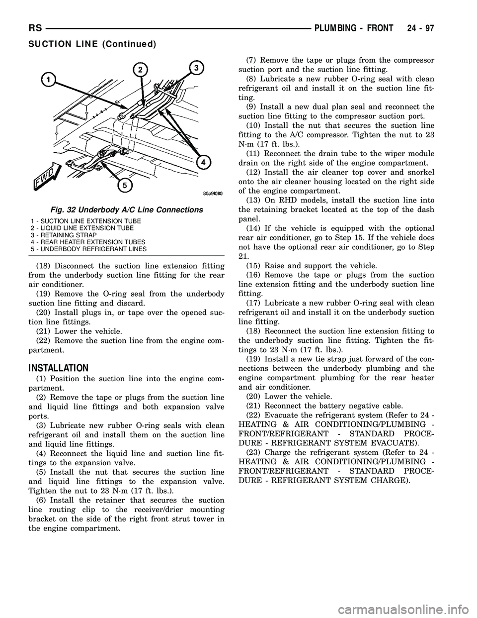
Fig. 32 Underbody A/C Line Connections
1 - SUCTION LINE EXTENSION TUBE
2 - LIQUID LINE EXTENSION TUBE
3 - RETAINING STRAP
4 - REAR HEATER EXTENSION TUBES
5 - UNDERBODY REFRIGERANT LINES
RSPLUMBING - FRONT24-97
SUCTION LINE (Continued)
Page 2257 of 2339
(17) Cut the tie strap located just forward of the
connections between the underbody plumbing and
the engine compartment plumbing for the rear heat-
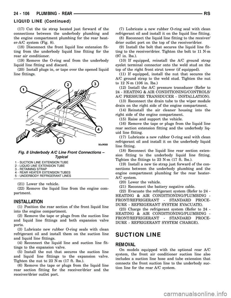
er-A/C system (Fig. 8).
(18) Disconnect the front liquid line extension fit-
ting from the underbody liquid line fitting for the
rear air conditioner.
(19) Remove the O-ring seal from the underbody
liquid line fitting and discard.
(20) Install plugs in, or tape over the opened liquid
line fittings.
(21) Lower the vehicle.
(22) Remove the liquid line from the engine com-
partment.
INSTALLATION
(1) Position the rear section of the front liquid line
into the engine compartment.
(2) Remove the tape or plugs from the suction line
and liquid line fittings and both expansion valve
ports.
(3) Lubricate new rubber O-ring seals with clean
refrigerant oil and install them on the suction line
and liquid line fittings.
(4) Reconnect the liquid line and suction line fit-
tings to the expansion valve.
(5) Install the nut that secures the suction line
and liquid line fittings to the expansion valve.
Tighten the nut to 23 N´m (17 ft. lbs.).
(6) Remove the tape or plugs from the liquid line
rear section fitting for the receiver/drier and the
receiver/drier outlet port.(7) Lubricate a new rubber O-ring seal with clean
refrigerant oil and install it on the liquid line fitting.
(8) Reconnect the liquid line fitting to the receiver/
drier outlet port on the top of the receiver/drier.
(9) Install the bolt that secures the liquid line fit-
ting to the receiver/drier. Tighten the bolt to 11 N´m
(97 in. lbs.).
(10) If equipped, reinstall the A/C ground strap
eyelet terminal connector onto the weld stud on the
top of the right front strut tower (if equipped).
(11) If equipped, install the nut that secures the
A/C ground strap to the weld stud. Tighten the nut
to 12 N´m (106 in. lbs.)
(12) Install the A/C pressure transducer (Refer to
24 - HEATING & AIR CONDITIONING/CONTROLS/
A/C PRESSURE TRANSDUCER - INSTALLATION).
(13) Reconnect the drain tube to the wiper module
drain on the right side of the engine compartment.
(14) Reinstall the air cleaner housing into the
right side of the engine compartment.
(15) Raise and support the vehicle.
(16) Remove the tape or plugs from the liquid line
rear section extension fitting and the underbody liq-
uid line fitting.
(17) Lubricate a new rubber O-ring seal with clean
refrigerant oil and install it on the underbody liquid
line fitting.
(18) Reconnect the liquid line rear section exten-
sion fitting to the underbody liquid line fitting.
Tighten the fittings to 23 N´m (17 ft. lbs.).
(19) Install a new tie strap just forward of the con-
nections between the underbody plumbing and the
engine compartment plumbing for the rear heater-
A/C system.
(20) Lower the vehicle.
(21) Reconnect the battery negative cable.
(22) Evacuate the refrigerant system (Refer to 24 -
HEATING & AIR CONDITIONING/PLUMBING -
FRONT/REFRIGERANT - STANDARD PROCE-
DURE - REFRIGERANT SYSTEM EVACUATE).
(23) Charge the refrigerant system (Refer to 24 -
HEATING & AIR CONDITIONING/PLUMBING -
FRONT/REFRIGERANT - STANDARD PROCE-
DURE - REFRIGERANT SYSTEM CHARGE).
SUCTION LINE
REMOVAL
On models equipped with the optional rear A/C
system, the front air conditioner suction line also
includes a suction line hose and tube extension that
connects the front suction line to the underbody suc-
tion line for the rear A/C system.
Fig. 8 Underbody A/C Line Front Connections ±
Typical
1 - SUCTION LINE EXTENSION TUBE
2 - LIQUID LINE EXTENSION TUBE
3 - RETAINING STRAP
4 - REAR HEATER EXTENSION TUBES
5 - UNDERBODY REFRIGERANT LINES
24 - 106 PLUMBING - REARRS
LIQUID LINE (Continued)
Page 2259 of 2339
(3) Lubricate new rubber O-ring seals with clean
refrigerant oil and install them on the suction line
and liquid line fittings.
(4) Reconnect the liquid line and suction line fit-
tings to the expansion valve.
(5) Install the nut that secures the suction line
and liquid line fittings to the front expansion valve.
Tighten the nut to 23 N´m (17 ft. lbs.).
(6) Engage the retainer that secures the suction
line routing clip to the receiver/drier mounting
bracket on the side of the right front strut tower in
the engine compartment.
(7) Remove the tape or plugs from the compressor
suction port and the suction line fitting.
(8) Lubricate a new rubber O-ring seal with clean
refrigerant oil and install it on the suction line fit-
ting.
(9) Reconnect the suction line fitting to the com-
pressor suction port.
(10) Install the nut that secures the suction line
fitting to the A/C compressor. Tighten the nut to 23
N´m (17 ft. lbs.).
(11) Reconnect the drain tube to the wiper module
drain on the right side of the engine compartment.
(12) Reinstall the air cleaner top cover and snorkel
onto the air cleaner housing located on the right side
of the engine compartment.
(13) Reconnect the battery negative cable.
(14) Raise and support the vehicle.
(15) Remove the tape or plugs from the suction
line extension fitting and the underbody suction line
fitting.
(16) Lubricate a new rubber O-ring seal with clean
refrigerant oil and install it on the underbody suction
line fitting.(17) Reconnect the suction line extension fitting to
the underbody suction line fitting. Tighten the fitting
to 23 N´m (17 ft. lbs.).
(18) Install a new tie strap just forward of the con-
nections between the underbody plumbing and the
engine compartment plumbing for the rear heater
and air conditioner.
(19) Lower the vehicle.
(20) Evacuate the refrigerant system (Refer to 24 -
HEATING & AIR CONDITIONING/PLUMBING -
FRONT/REFRIGERANT - STANDARD PROCE-
DURE - REFRIGERANT SYSTEM EVACUATE).
(21) Charge the refrigerant system (Refer to 24 -
HEATING & AIR CONDITIONING/PLUMBING -
FRONT/REFRIGERANT - STANDARD PROCE-
DURE - REFRIGERANT SYSTEM CHARGE).
UNDERBODY LINES
DESCRIPTION
The underbody heater-A/C plumbing is used only
on models with the optional rear heater-A/C system
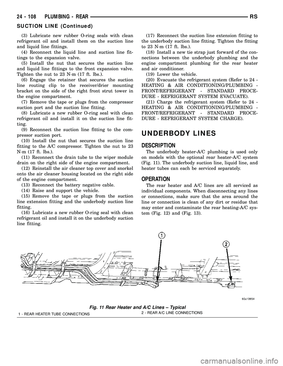
(Fig. 11). The underbody suction line, liquid line, and
heater tubes can each be serviced separately.
OPERATION
The rear heater and A/C lines are all serviced as
individual components. When disconnecting any lines
or connections, make sure that the area around the
line or connection is clean of any dirt or residue that
may enter and contaminate the rear heating-A/C sys-
tem (Fig. 12) and (Fig. 13).
Fig. 11 Rear Heater and A/C Lines ± Typical
1 - REAR HEATER TUBE CONNECTIONS2 - REAR A/C LINE CONNECTIONS
24 - 108 PLUMBING - REARRS
SUCTION LINE (Continued)
Page 2264 of 2339
CABIN HEATER
TABLE OF CONTENTS
page page
CABIN HEATER
DESCRIPTION........................113
OPERATION
MANUAL TEMPERATURE CONTROL
SYSTEM...........................113
AUTOMATIC TEMPERATURE CONTROL
SYSTEM...........................114
WARNING............................114
DIAGNOSIS AND TESTING
SUPPLEMENTAL CABIN HEATER........114
AIR INTAKE PIPE
REMOVAL............................115
INSTALLATION........................115
EXHAUST TUBE
REMOVAL............................116
INSTALLATION........................116
FUEL DOSING PUMP
DESCRIPTION........................117
OPERATION..........................117REMOVAL............................117
INSTALLATION........................117
FUEL LINE
STANDARD PROCEDURE
CLEANING..........................118
REMOVAL............................118
INSTALLATION........................118
HEATER HOSES
REMOVAL............................119
INSTALLATION........................119
HEATER PIPES
REMOVAL............................119
INSTALLATION........................120
HEATER UNIT
REMOVAL............................121
INSTALLATION........................122
HEATER WIRING
REMOVAL............................122
INSTALLATION........................122
CABIN HEATER
DESCRIPTION
Vehicles equipped with the diesel engine are also
equipped with a supplemental cabin heater. This
cabin heater is mounted under the vehicle and oper-
ates similar to an oil fired furnace. The heater burns
small amounts of fuel to provide additional heat to
the coolant. Coolant is routed from the engine, to the
supplemental cabin heater and then to the front
heater core. This provides additional heat to the pas-
senger compartment. The supplemental cabin heater
system is interfaced to the vehicles on-board com-
puter systems and DRBIIItdiagnostics.
The supplemental cabin heater has an electronic
control module that monitors the heat output of the
heater. The cabin heater operates at full load (5 kW),
half load or idle mode (no additional heat) depending
on engine coolant temperature.
When ambient temperatures are lower than 15É C
(60É F), the supplemental cabin heater automatically
operates once each ignition cycle for five minutes.
This assures a good fuel supply is always present for
the supplemental cabin heater.
OPERATION
MANUAL TEMPERATURE CONTROL SYSTEM
The supplemental cabin heater is activated via the
temperature slide control or knob on the A/C-heater
control when equipped with the manual temperature
control (MTC) system. If the slide control or knob is
moved to or above the upper set point the cabin
heater is activated. The cabin heater can operate in a
full or partial load range as well as an idle mode all
dependent on the engine coolant temperature. The
cabin heater will also turn off if the A/C-heater tem-
perature control is lowered to less than the lower set
point. The cabin heater can take up to three minutes
to completely shut down when either the heater tem-
perature is set below the lower set point or the vehi-
cle ignition is shut down.
NOTE: Do not apply a strong vacuum source such
as a garage ventilation system directly on the sup-
plemental cabin heater exhaust line. Too strong of a
vacuum can prevent the supplemental cabin heater
from starting. If required, place the vacuum source
at least 75 mm (3 in.) away from the exhaust line.
RSCABIN HEATER24 - 113
Page 2265 of 2339
The supplemental cabin heater only operates when
the engine is running, the mileage exceeds 8 kilome-
ter (5 mph) and the fuel tank volume exceeds 1/8 of a
tank. The supplemental heater control module moni-
tors blower speed and combustion during its start-up.
The cabin heater should operate if the coolant tem-
perature is below 40É C (104É F).
AUTOMATIC TEMPERATURE CONTROL
SYSTEM
The automatic temperature control (ATC) system
will activate the supplemental cabin heater based on
engine coolant temperature and interior component
settings. The cabin heater can operate in a full or
partial load range as well as an idle mode all depen-
dent on the engine coolant temperature. The cabin
heater will also turn off if the A/C-heater tempera-
ture control is lowered to less than the lower set
point. The cabin heater can take up to three minutes
to completely shut down when either the heater tem-
perature is set below the lower set point or the vehi-
cle ignition is shut down.
NOTE: Do not apply a strong vacuum source such
as a garage ventilation system directly on the sup-
plemental cabin heater exhaust line. Too strong of a
vacuum can prevent the supplemental cabin heater
from starting. If required, place the vacuum source
at least 75 mm (3 in.) away from the exhaust line.
The supplemental cabin heater only operates when
the engine is running, the mileage exceeds 8 kilome-ter (5 mph) and the fuel tank volume exceeds 1/8 of a
tank. The supplemental heater control module moni-
tors blower speed and combustion during its start-up.
The cabin heater should operate if the coolant tem-
perature is below 40É C (104É F).
WARNING
WARNING: DO NOT OPERATE THE DIESEL SUP-
PLEMENTAL CABIN HEATER IN AN ENCLOSED
AREA SUCH AS A GARAGE THAT DOES NOT HAVE
EXHAUST VENTILATION FACILITIES. ALWAYS VENT
THE CABIN HEATER EXHAUST WHEN OPERATING
THE CABIN HEATER. ALLOW THE DIESEL SUPPLE-
MENTAL CABIN HEATER TO COOL BEFORE PER-
FORMING ANY SERVICE PROCEDURES TO THE
CABIN HEATER. VERIFY THAT ALL DIESEL SUP-
PLEMENTAL CABIN HEATER FUEL LINES ARE
SECURELY FASTENED TO THEIR RESPECTIVE
COMPONENTS BEFORE PERFORMING ANY SER-
VICE PROCEDURES TO THE CABIN HEATER. FAIL-
URE TO FOLLOW THESE INSTRUCTION MAY
RESULT IN PERSONAL INJURY OR DEATH.
DIAGNOSIS AND TESTING
SUPPLEMENTAL CABIN HEATER
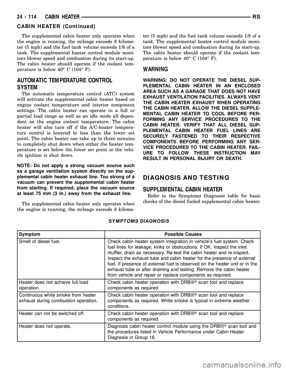
Refer to the Symptoms Diagnosis table for basic
checks of the diesel fueled supplemental cabin heater.
SYMPTOMS DIAGNOSIS
Symptom Possible Causes
Smell of diesel fuel. Check cabin heater system integration in vehicle's fuel system. Check
fuel lines for leakage, kinks or obstructions. If OK, Inspect the inlet
muffler, drain as necessary. Re-test the cabin heater and re-inspect.
Inspect the exhaust tube and cabin heater for the presence of external
fuel. If presence of external fuel is observed on the heater unit or in the
exhaust tube or after draining and testing. Remove the cabin heater
from vehicle and repair or replace components as required.
Heater does not achieve full load
operation.Check cabin heater operation with DRBIIITscan tool and replace
components as required.
Continuous white smoke from heater
exhaust during combustion operation.Check cabin heater operation with DRBIIITscan tool and replace
components as required. White smoke is typical in extreme weather
conditions.
Heater can not be switched off. Check cabin heater operation with DRBIIITscan tool and replace
components as required.
Heater does not operate. Diagnosis cabin heater control module using the DRBIIITscan tool and
the procedures listed in Vehicle Performance under Cabin Heater
Diagnosis in Group 18.
24 - 114 CABIN HEATERRS
CABIN HEATER (Continued)
Page 2268 of 2339
FUEL DOSING PUMP
DESCRIPTION
The dosing pump is a combined delivery, dosing
and shut-off system for the fuel supply to the supple-
mental cabin heater from the vehicle fuel tank.
OPERATION
The dosing pump is an electrically operated pump
that receives its operation instructions from the sup-
plemental cabin heater control module. The pump
supplies diesel fuel from the vehicle fuel tank to the
cabin heater.
REMOVAL
NOTE: The dosing pump is serviceable without
removing the supplemental cabin heater from the
vehicle.
(1) Disconnect and isolate the negative battery
cable.
CAUTION: Make sure that the hoist is properly posi-
tioned under the vehicle to prevent damage to the
flexible section of the cabin heater exhaust tube.
(2) Raise and support the vehicle.
(3) Disconnect the wiring harness connector to the
dosing pump by depressing the integral spring and
pulling the connector away from the pump.
NOTE: Utilize an approved fuel storage container to
catch any residual fuel that may drain from the
heater fuel hose or the dosing pump.
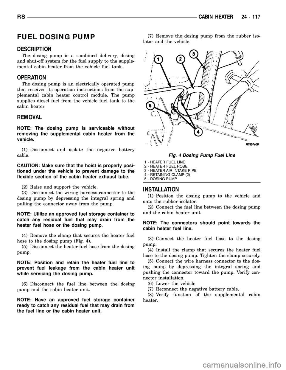
(4) Remove the clamp that secures the heater fuel
hose to the dosing pump (Fig. 4).
(5) Disconnect the heater fuel hose from the dosing
pump.
NOTE: Position and retain the heater fuel line to
prevent fuel leakage from the cabin heater unit
while servicing the dosing pump.
(6) Disconnect the fuel line between the dosing
pump and the cabin heater unit.
NOTE: Have an approved fuel storage container
ready to catch any residual fuel that may drain from
the fuel line or the cabin heater unit.(7) Remove the dosing pump from the rubber iso-
lator and the vehicle.
INSTALLATION
(1) Position the dosing pump to the vehicle and
onto the rubber isolator.
(2) Connect the fuel line between the dosing pump
and the cabin heater unit.
NOTE: The connectors should point towards the
cabin heater fuel line.
(3) Connect the heater fuel hose to the dosing
pump.
(4) Install the clamp that secures the heater fuel
hose to the dosing pump. Tighten the clamp securely.
(5) Connect the wire harness connector to the dos-
ing pump by depressing the integral spring and
pushing the connector toward the pump. Verify con-
nector installation.
(6) Lower the vehicle
(7) Reconnect the negative battery cable.
(8) Verify function of the supplemental cabin
heater.
Fig. 4 Dosing Pump Fuel Line
1 - HEATER FUEL LINE
2 - HEATER FUEL HOSE
3 - HEATER AIR INTAKE PIPE
4 - RETAINING CLAMP (2)
5 - DOSING PUMP
RSCABIN HEATER24 - 117
Page 2276 of 2339
richer than optimum A/F mixture or vice versa. As
the PCM adjusts the air/fuel ratio, the sensor must
be able to rapidly detect the change. As the sensor
ages, it could take longer to detect the changes in the
oxygen content of the exhaust gas. The rate of
change that an oxygen sensor experiences is called
'Big Slope'. The PCM checks the oxygen sensor volt-
age in increments of a few milliseconds.
Reduced Output Voltage (Half Cycle)ÐThe
output voltage of the O2S ranges from 0 to 1 volt. A
good sensor can easily generate any output voltage in
this range as it is exposed to different concentrations
of oxygen. To detect a shift in the A/F mixture (lean
or rich), the output voltage has to change beyond a
threshold value. A malfunctioning sensor could have
difficulty changing beyond the threshold value. Many
times the condition is only temporey and the sensor
will recover. Under normal conditions the voltage sig-
nal surpasses the threshold, and a counter is incre-
mented by one. This is called the Half Cycle Counter.
Heater PerformanceÐThe heater is tested by a
separate monitor. Refer to the Oxygen Sensor Heater
Monitor.
OPERATIONÐAs the Oxygen Sensor signal
switches, the PCM monitors the half cycle and big
slope signals from the oxygen sensor. If during the
test neither counter reaches a predetermined value, a
malfunction is entered and a Freeze Frame is stored.
Only one counter reaching its predetermined value is
needed for the monitor to pass.
The Oxygen Sensor Signal Monitor is a two trip
monitor that is tested only once per trip. When the
Oxygen Sensor fails the test in two consecutive trips,
the MIL is illuminated and a DTC is set. The MIL is
extinguished when the Oxygen Sensor monitor
passes in three consecutive trips. The DTC is erased
from memory after 40 consecutive warm-up cycles
without test failure.
Enabling ConditionsÐThe following conditions
must typically be met for the PCM to run the oxygen
sensor monitor:
²Battery voltage
²Engine temperature
²Engine run time
²Engine run time at a predetermined speed
²Engine run time at a predetermined speed and
throttle opening
²Transmission in gear (automatic only)
²Fuel system in Closed Loop
²Long Term Adaptive (within parameters)
²Power Steering Switch in low PSI (no load)
²Engine at idle
²Fuel level above 15%
²Ambient air temperature
²Barometric pressure²Engine RPM within acceptable range of desired
idle
²Closed throttle speed
Pending ConditionsÐThe Task Manager typi-
cally does not run the Oxygen Sensor Signal Monitor
if overlapping monitors are running or the MIL is
illuminated for any of the following:
²Misfire Monitor
²Front Oxygen Sensor and Heater Monitor
²MAP Sensor
²Vehicle Speed Sensor
²Engine Coolant Temperature Sensor
²Throttle Position Sensor
²Engine Controller Self Test Faults
²Cam or Crank Sensor
²Injector and Coil
²Idle Air Control Motor
²EVAP Electrical
²EGR Solenoid Electrical
²Intake Air Temperature
²5 Volt Feed
ConflictÐThe Task Manager does not run the
Oxygen Sensor Monitor if any of the following condi-
tions are present:
²A/C ON (A/C clutch cycling temporarily sus-
pends monitor)
²Purge flow in progress
²Ethenal content learn is taking place and the
ethenal used once flag is set
SuspendÐThe Task Manager suspends maturing
a fault for the Oxygen Sensor Monitor if an of the fol-
lowing are present:
²Oxygen Sensor Heater Monitor, Priority 1
²Misfire Monitor, Priority 2
OXYGEN SENSOR HEATER MONITOR (NGC)
DESCRIPTIONÐIf the Oxygen sensor (O2S) DTC
as well as a O2S heater DTC is present, the O2S
Heater DTC MUST be repaired first. After the O2S
Heater is repaired, verify that the sensor circuit is
operating correctly.
The voltage reading taken from the O2S are very
temperature sensitive. The readings taken from the
O2S are not accurate below 300 degrees C. Heating
the O2S is done to allow the engine controller to shift
to closed loop control as soon as possible. The heating
element used to heat the O2S must be tested to
ensure that it is heating the sensor properly. Starting
with the introduction on the NGC module the strat-
egy for checking the heater circuit has changed. The
heater resistance is checked by the NGC almost
immediately after the engine is started. The same
O2S heater return pin used to read the heater resis-
tance is capable of detecting an open circuit, a
shorted high or shorted low condition.
RSEMISSIONS CONTROL25-3
EMISSIONS CONTROL (Continued)
Page 2280 of 2339
The information obtained by the sensor is used to
calculate the fuel injector pulse width. The PCM is
programmed to maintain the optimum air/fuel ratio.
At this mixture ratio, the catalyst works best to
remove hydrocarbons (HC), carbon monoxide (CO)
and nitrous oxide (NOx) from the exhaust.
The O2S is also the main sensing element for the
EGR (if equipped), Catalyst and Fuel Monitors.
The O2S may fail in any or all of the following
manners:
²Slow response rate
²Reduced output voltage
²Dynamic shift
²Shorted or open circuits
Response rate is the time required for the sensor to
switch from lean to rich once it is exposed to a richer
than optimum A/F mixture or vice versa. As the sen-
sor starts malfunctioning, it could take longer to
detect the changes in the oxygen content of the
exhaust gas.
The output voltage of the O2S ranges from 0 to 1
volt (voltages are offset by 2.5 volts on NGC vehi-
cles). A good sensor can easily generate any output
voltage in this range as it is exposed to different con-
centrations of oxygen. To detect a shift in the A/F
mixture (lean or rich), the output voltage has to
change beyond a threshold value. A malfunctioning
sensor could have difficulty changing beyond the
threshold value.
OXYGEN SENSOR HEATER MONITOR
If there is an oxygen sensor (O2S) DTC as well as
a O2S heater DTC, the O2S heater fault MUST be
repaired first. After the O2S fault is repaired, verify
that the heater circuit is operating correctly.
Effective control of exhaust emissions is achieved
by an oxygen feedback system. The most important
element of the feedback system is the O2S. The O2S
is located in the exhaust path. Once it reaches oper-
ating temperatures of 300É to 350ÉC (572 É to 662ÉF),
the sensor generates a voltage that is inversely pro-
portional to the amount of oxygen in the exhaust.
The information obtained by the sensor is used to
calculate the fuel injector pulse width. This main-
tains a 14.7 to 1 Air Fuel (A/F) ratio. At this mixture
ratio, the catalyst works best to remove hydrocarbons
(HC), carbon monoxide (CO) and nitrogen oxide
(NOx) from the exhaust.
The voltage readings taken from the O2S are very
temperature sensitive. The readings are not accurate
below 300ÉC. Heating of the O2S is done to allow the
engine controller to shift to closed loop control as
soon as possible. The heating element used to heat
the O2S must be tested to ensure that it is heating
the sensor properly.The O2S circuit is monitored for a drop in voltage.
The sensor output is used to test the heater by iso-
lating the effect of the heater element on the O2S
output voltage from the other effects.
EGR MONITOR (if equipped)
The Powertrain Control Module (PCM) performs
an on-board diagnostic check of the EGR system.
The EGR monitor is used to test whether the EGR
system is operating within specifications. The diag-
nostic check activates only during selected engine/
driving conditions. When the conditions are met, the
EGR is turned off (solenoid energized) and the O2S
compensation control is monitored. Turning off the
EGR shifts the air fuel (A/F) ratio in the lean direc-
tion. The O2S data should indicate an increase in the
O2 concentration in the combustion chamber when
the exhaust gases are no longer recirculated. While
this test does not directly measure the operation of
the EGR system, it can be inferred from the shift in
the O2S data whether the EGR system is operating
correctly. Because the O2S is being used, the O2S
test must pass its test before the EGR test. Also
looks at EGR linear potentiometer for feedback.
MISFIRE MONITOR
Excessive engine misfire results in increased cata-
lyst temperature and causes an increase in HC emis-
sions. Severe misfires could cause catalyst damage.
To prevent catalytic convertor damage, the PCM
monitors engine misfire.
The Powertrain Control Module (PCM) monitors
for misfire during most engine operating conditions
(positive torque) by looking at changes in the crank-
shaft speed. If a misfire occurs the speed of the
crankshaft will vary more than normal.
FUEL SYSTEM MONITOR
To comply with clean air regulations, vehicles are
equipped with catalytic converters. These converters
reduce the emission of hydrocarbons, oxides of nitro-
gen and carbon monoxide. The catalyst works best
when the air fuel (A/F) ratio is at or near the opti-
mum of 14.7 to 1.
The PCM is programmed to maintain the optimum
air/fuel ratio. This is done by making short term cor-
rections in the fuel injector pulse width based on the
O2S output. The programmed memory acts as a self
calibration tool that the engine controller uses to
compensate for variations in engine specifications,
sensor tolerances and engine fatigue over the life
span of the engine. By monitoring the actual air-fuel
ratio with the O2S (short term) and multiplying that
with the program long-term (adaptive) memory and
comparing that to the limit, it can be determined
whether it will pass an emissions test. If a malfunc-
RSEMISSIONS CONTROL25-7
EMISSIONS CONTROL (Continued)