Page 2055 of 2339
Fig. 128 FRONT SIDE RAIL - SHORT WHEEL BASE ONLY
23 - 276 BODY STRUCTURERS
WELD LOCATIONS (Continued)
Page 2062 of 2339
Fig. 137 FRONT SIDE RAILS TO LOWER DASH PANEL
RSBODY STRUCTURE23 - 283
WELD LOCATIONS (Continued)
Page 2078 of 2339
Fig. 156 TAIL LAMP - LONG WHEEL BASE ONLY
Fig. 157 SLIDING DOOR LATCH - LONG WHEEL BASE ONLY
RSBODY STRUCTURE23 - 299
WELD LOCATIONS (Continued)
Page 2100 of 2339
Fig. 180 UPPER WINDSHIELD FRAME/ROOF PANEL - LONG WHEEL BASE ONLY
Fig. 181 ROOF BOWS/INNER ROOF SIDE RAILS
RSBODY STRUCTURE23 - 321
WELD LOCATIONS (Continued)
Page 2117 of 2339
Fig. 199 ROOF PANEL/ROOF RAIL - SHORT WHEEL BASE ONLY
23 - 338 BODY STRUCTURERS
WELD LOCATIONS (Continued)
Page 2127 of 2339
Fig. 211 REINFORCEMENTS, SIDE RAILS, COWL SIDE PANELS AND DASH PANEL - RIGHT HAND DRIVE
23 - 348 BODY STRUCTURERS
WELD LOCATIONS (Continued)
Page 2152 of 2339

HEATING & AIR CONDITIONING
TABLE OF CONTENTS
page page
HEATING & AIR CONDITIONING
DESCRIPTION
ENGINE COOLING SYSTEM
REQUIREMENTS.......................1
HEATER AND AIR CONDITIONER..........1
MANUAL SINGLE ZONE.................2
MANUAL DUAL ZONE...................2
MANUAL THREE ZONE..................2
AUTOMATIC TEMPERATURE CONTROL....3
OPERATION
HEATER AND AIR CONDITIONER..........4
MANUAL SINGLE ZONE.................4
MANUAL DUAL ZONE...................5
MANUAL THREE ZONE..................5AUTOMATIC TEMPERATURE CONTROL....5
DIAGNOSIS AND TESTING
A/C COOL DOWN TEST.................6
A/C PERFORMANCE TEST...............7
HEATER PERFORMANCE TEST..........10
SPECIFICATIONS
A/C SYSTEM.........................11
CONTROLS - FRONT.....................13
CONTROLS - REAR......................33
DISTRIBUTION - FRONT...................42
DISTRIBUTION - REAR....................56
PLUMBING - FRONT.....................64
PLUMBING - REAR......................98
CABIN HEATER........................113
HEATING & AIR
CONDITIONING
DESCRIPTION
ENGINE COOLING SYSTEM REQUIREMENTS
To maintain the performance level of the heating,
ventilation and air conditioning (HVAC) system, the
engine cooling system must be properly maintained.
The use of a bug screen is not recommended. Any
obstructions in front of the radiator or condenser will
reduce the performance of the air conditioning and
engine cooling systems.
The engine cooling system includes the radiator,
thermostat, radiator hoses and the engine coolant
pump. Refer to Cooling for more information before
opening or attempting any service to the engine cool-
ing system.
HEATER AND AIR CONDITIONER
A manually controlled single zone type heating-air
conditioning system, manually controlled dual zone
type heating-air conditioning system, manually con-
trolled three zone type heating-air conditioning sys-
tem or an automatic controlled three zone type
heating-air conditioning system is available on this
model.
All vehicles are equipped with a common heater,
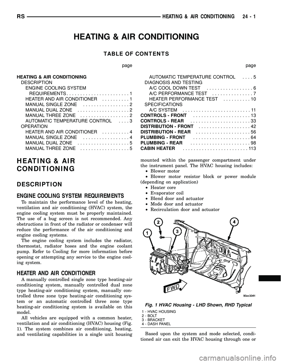
ventilation and air conditioning (HVAC) housing (Fig.
1). The system combines air conditioning, heating,
and ventilating capabilities in a single unit housingmounted within the passenger compartment under
the instrument panel. The HVAC housing includes:
²Blower motor
²Blower motor resistor block or power module
(depending on application)
²Heater core
²Evaporator coil
²Blend door and actuator
²Mode door and actuator
²Recirculation door and actuator
Based upon the system and mode selected, condi-
tioned air can exit the HVAC housing through one or
Fig. 1 HVAC Housing - LHD Shown, RHD Typical
1 - HVAC HOUSING
2 - BOLT
3 - BRACKET
4 - DASH PANEL
RSHEATING & AIR CONDITIONING24-1
Page 2153 of 2339

a combination of the three main housing outlets:
defrost, panel or floor. The defrost and panel outlets
are located on the top of the housing and the floor
outlet is located on the bottom of the housing. Once
the conditioned air exits the unit housing, it is fur-
ther directed through molded plastic ducts to the var-
ious outlets in the vehicle interior. These outlets and
their locations are as follows:
²Defroster Outlet- A single large defroster out-
let is located in the center of the instrument panel
top cover, near the base of the windshield.
²Side Window Demister Outlets- There are
two side window demister outlets, one is located at
each outboard end of the instrument panel, near the
A-pillars.
²Panel Outlets- There are five panel outlets in
the instrument panel, one located near each outboard
end of the instrument panel facing the rear of the
vehicle and three located near the top of the instru-
ment panel center bezel.
²Front Floor Outlets- There are two front floor
outlets, one located above each side of the center of
the floor panel near the dash panel.
MANUAL SINGLE ZONE
The manual single zone heating and A/C system
allows one temperature setting for the entire vehicle.
The full range of temperatures that the system can
produce are available by rotating the temperature
control located on the A/C-heater control.
The A/C-heater control and integral computer is
located in the instrument panel and contains:
²a rear window defogger on/off switch. Contains
an LED that illuminates to show when the function
is operational.
²an air recirculation on/off switch. The Recircu-
late button contains an LED that illuminates to show
when the function is in operation.
²an air conditioning on/off switch. The Snowflake
button contains an LED that illuminates to shown
when the function is in operation.
²a rotary knob for fan speed selection and turn-
ing the heater-A/C system off.
²a rotary knob for temperature control of the dis-
charged air.
²a rotary knob for mode control.
MANUAL DUAL ZONE
The manual dual zone heating and A/C system
allows completely independent side-to-side tempera-
ture control of the discharge air.
The A/C-heater control and integral computer is
located in the instrument panel and contains:
²a rear window defogger on/off switch. Contains
an LED that illuminates to show when the function
is operational.²slide controls for completely independent side-to-
side temperature control of the discharged air. The
full range of temperature that the system can pro-
duce in any mode is available on either side of the
vehicle by independently positioning the slide con-
trols on the instrument panel.
²an air recirculation on/off switch. The Recircu-
late button contains an LED that illuminates to show
when the function is in operation.
²an air conditioning on/off switch. The Snowflake
button contains an LED that illuminates to shown
when the function is in operation.
²a rotary knob for fan speed selection and turn-
ing the heater-A/C system off.
²a rotary knob for mode control.
MANUAL THREE ZONE
The fully adjustable manual three zone front and
rear heating and A/C system allows intermediate
seat passengers the ability to regulate air tempera-
ture as well as fan speed and provides floor outlets to
the rear of the right sliding door and overhead out-
lets at each rear outboard seating position. Primary
control for the rear blower is on the front A/C-heater
control. All controls are identified by ISO graphic
symbols.
FRONT CONTROL PANEL
The front A/C-heater control and integral computer
mounted in the instrument panel contains:
²a rear window defogger on/off switch.
²slide controls for completely independent side-to-
side temperature control of the discharge air. The full
range of temperature that the system can produce in
any mode is available on either side of the vehicle by
independently positioning the slide controls on the
instrument panel.
²an air recirculation button. The Recirculate but-
ton contains an LED that illuminates to show when
the function is in operation.
²an air conditioning button that allows the com-
pressor to be turned on/off. The Snowflake button
contains an LED that illuminates to shown when the
function is in operation.
²a rotary knob for front fan speed selection and
turning the heater-A/C system off.
²a rotary knob for rear fan speed selection.
²a rotary knob for mode control.
REAR CONTROL PANEL
The rear A/C-heater control centrally mounted in
the headliner allows intermediate seat passengers to
adjust rear air distribution, temperature and blower
motor speed when the center knob on the front A/C-
heater control is set to the Rear position. The rear
A/C-heater control contains:
24 - 2 HEATING & AIR CONDITIONINGRS
HEATING & AIR CONDITIONING (Continued)