2005 CHRYSLER VOYAGER lock code
[x] Cancel search: lock codePage 1424 of 2339
(19) Position the lower shroud on the column (Fig.
8). Install the lower shroud mounting screw. Tighten
the screw to 2 N´m (17 in. lbs.) torque.
(20) If equipped with adjustable pedals, Connect
the wiring connector for the switch (Fig. 7) to the col-
umn wiring harness.
(21) Position the upper shroud on top of the lower
shroud and snap it into place. Install the upper
shroud mounting screws (Fig. 6). Tighten the screws
to 2 N´m (17 in. lbs.) torque.
(22) Inspect shroud mating surfaces for excessive
gaps and correct as necessary.
(23) Install the cluster trim bezel (Refer to 23 -
BODY/INSTRUMENT PANEL/CLUSTER BEZEL -
INSTALLATION).
(24) Install the knee blocker/steering column cover
plate. (Refer to 23 - BODY/INSTRUMENT PANEL/
KNEE BLOCKER - INSTALLATION)
(25) Install the parking brake handle link.
(26) Install the knee blocker/steering column open-
ing cover. (Refer to 23 - BODY/INSTRUMENT PAN-
EL/STEERING COLUMN OPENING COVER -
INSTALLATION)
(27) Align the splines and install the steering
wheel on the steering column shaft(Refer to 19 -
STEERING/COLUMN/STEERING WHEEL -
INSTALLATION).
(28) Install the damper over the steering column
shaft (Fig. 4).
(29) Install the steering wheel retaining bolt (Fig.
4). Tighten the bolt to 61 N´m (45 ft. lbs.) torque.
(30) If the steering wheel is equipped with remote
audio controls, connect the wiring connector to the
clockspring (Fig. 4).
(31) Connect the two squib connectors to the
driver airbag (Fig. 3). The connectors are color coded
to avoid connector mix-up.
(32) Connect the speed control and horn connector
to the clockspring (Fig. 3).
(33) Install the airbag to the steering wheel.
Install the driver airbag mounting screws (Fig. 2).
Tighten screws to 10 N´m (90 in. lbs.) torque.
(34) Connect the battery negative (ground) cable to
battery post following special Diagnosis And Testing
procedure. (Refer to 8 - ELECTRICAL/RESTRAINTS
- DIAGNOSIS AND TESTING)
(35) Check operation of all steering column
mounted components.
(36) Road test vehicle to ensure proper operation
of steering.SPECIFICATIONS
COLUMN FASTENER TORQUE
DESCRIPTION N´mFt.
Lbs.In.
Lbs.
Driver Airbag Mounting Screws 10 Ð 90
Multi-Function Switch Mounting
Housing Set-Screw14 Ð 124
Shroud Attaching Screws - Fixed 3 Ð 23
Shroud Attaching Screws -
Lower/Upper2Ð17
SKIM Attaching Screw 4 Ð 30
Steering Column Coupling Pinch
Bolt28 Ð 250
Steering Column Mounting Nuts 12 Ð 105
Steering Wheel Retaining Bolt 61 45 Ð
IGNITION SWITCH
REMOVAL
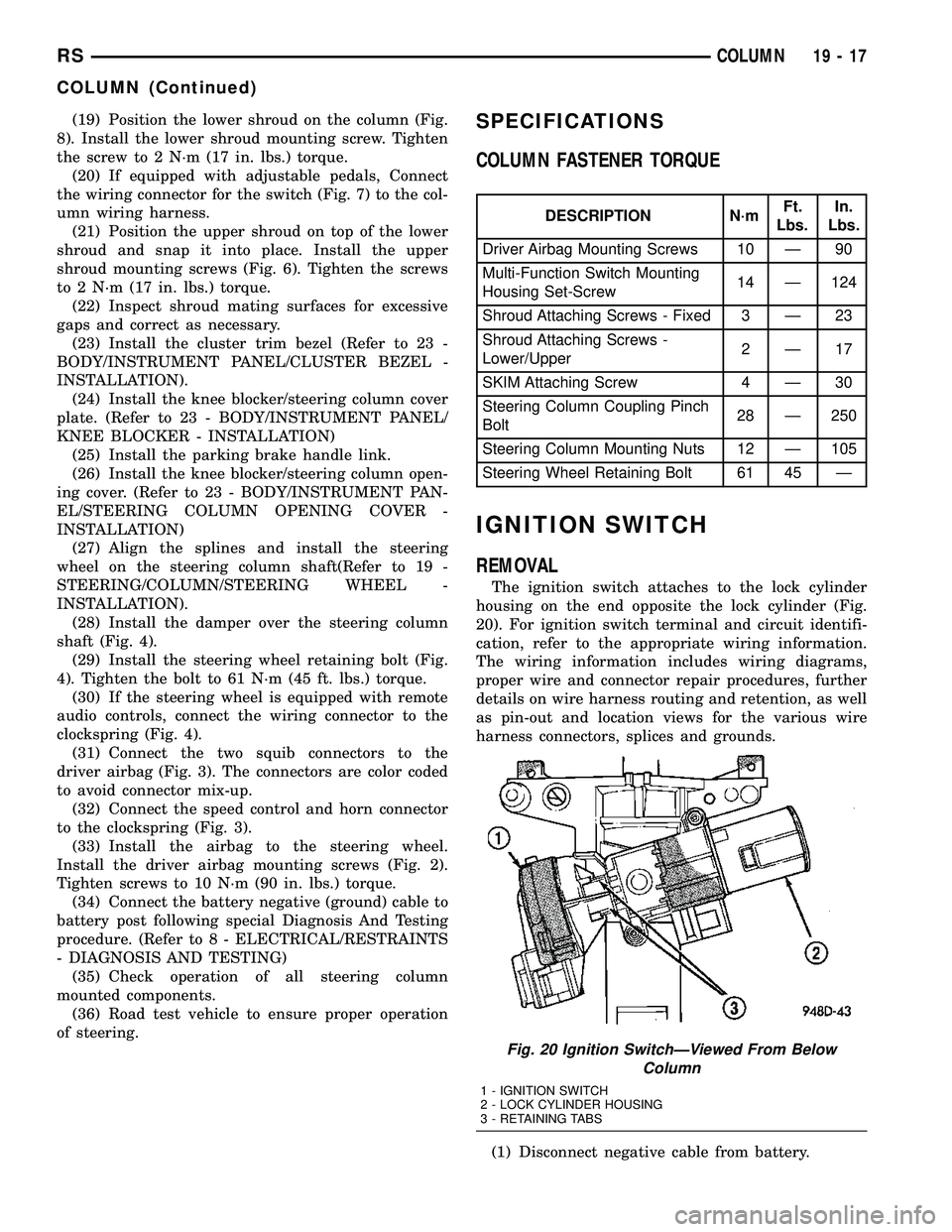
The ignition switch attaches to the lock cylinder
housing on the end opposite the lock cylinder (Fig.
20). For ignition switch terminal and circuit identifi-
cation, refer to the appropriate wiring information.
The wiring information includes wiring diagrams,
proper wire and connector repair procedures, further
details on wire harness routing and retention, as well
as pin-out and location views for the various wire
harness connectors, splices and grounds.
(1) Disconnect negative cable from battery.
Fig. 20 Ignition SwitchÐViewed From Below
Column
1 - IGNITION SWITCH
2 - LOCK CYLINDER HOUSING
3 - RETAINING TABS
RSCOLUMN19-17
COLUMN (Continued)
Page 1510 of 2339
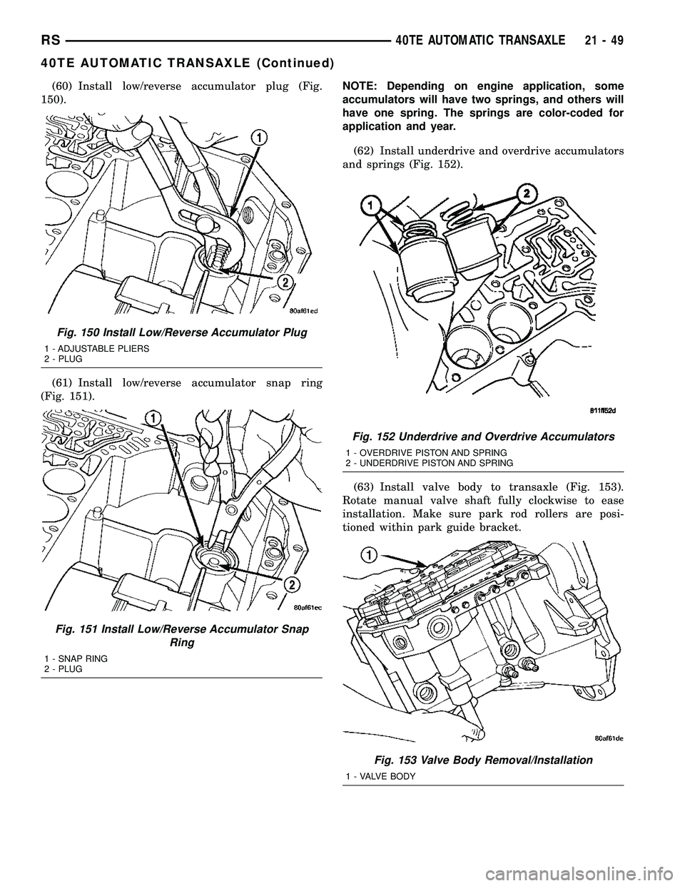
(60) Install low/reverse accumulator plug (Fig.
150).
(61) Install low/reverse accumulator snap ring
(Fig. 151).NOTE: Depending on engine application, some
accumulators will have two springs, and others will
have one spring. The springs are color-coded for
application and year.
(62) Install underdrive and overdrive accumulators
and springs (Fig. 152).
(63) Install valve body to transaxle (Fig. 153).
Rotate manual valve shaft fully clockwise to ease
installation. Make sure park rod rollers are posi-
tioned within park guide bracket.
Fig. 150 Install Low/Reverse Accumulator Plug
1 - ADJUSTABLE PLIERS
2 - PLUG
Fig. 151 Install Low/Reverse Accumulator Snap
Ring
1 - SNAP RING
2 - PLUG
Fig. 152 Underdrive and Overdrive Accumulators
1 - OVERDRIVE PISTON AND SPRING
2 - UNDERDRIVE PISTON AND SPRING
Fig. 153 Valve Body Removal/Installation
1 - VALVE BODY
RS40TE AUTOMATIC TRANSAXLE21-49
40TE AUTOMATIC TRANSAXLE (Continued)
Page 1592 of 2339
OPERATION
The Transmission Range Sensor (TRS) (Fig. 307)
communicates shift lever position (SLP) to the PCM/
TCM as a combination of open and closed switches.
Each shift lever position has an assigned combina-
tion of switch states (open/closed) that the PCM/TCM
receives from four sense circuits. The PCM/TCM
interprets this information and determines the
appropriate transaxle gear position and shift sched-
ule.
Since there are four switches, there are 16 possible
combinations of open and closed switches (codes).
Seven of these codes are related to gear position and
three are recognized as ªbetween gearº codes. This
results in six codes which should never occur. These
are called ªinvalidº codes. An invalid code will result
in a DTC, and the PCM/TCM will then determine the
shift lever position based on pressure switch data.
This allows reasonably normal transmission opera-
tion with a TRS failure.
TRS SWITCH STATES
SLP T42 T41 T3 T1
PCL CL CL OP
RCL OP OP OP
NCL CL OP CL
ODOP OP OP CL
3OP OP CL OP
LCL OP CL CL
TRANSMISSION TEMPERATURE SENSOR
The TRS has an integrated thermistor (Fig. 308)
that the PCM/TCM uses to monitor the transmis-
sion's sump temperature. Since fluid temperature
can affect transmission shift quality and convertor
lock up, the PCM/TCM requires this information to
determine which shift schedule to operate in. The
PCM also monitors this temperature data so it can
energize the vehicle cooling fan(s) when a transmis-
sion ªoverheatº condition exists. If the thermistor cir-
cuit fails, the PCM/TCM will revert to calculated oil
temperature usage.
CALCULATED TEMPERATURE
A failure in the temperature sensor or circuit will
result in calculated temperature being substituted for
actual temperature. Calculated temperature is a pre-dicted fluid temperature which is calculated from a
combination of inputs:
²Battery (ambient) temperature
²Engine coolant temperature
²In-gear run time since start-up
REMOVAL
(1) Remove valve body assembly from transaxle.
(Refer to 21 - TRANSMISSION/TRANSAXLE/AUTO-
MATIC - 41TE/VALVE BODY - REMOVAL)
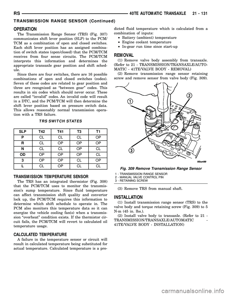
(2) Remove transmission range sensor retaining
screw and remove sensor from valve body (Fig. 309).
(3) Remove TRS from manual shaft.
INSTALLATION
(1) Install transmission range sensor (TRS) to the
valve body and torque retaining screw (Fig. 309) to 5
N´m (45 in. lbs.).
(2) Install valve body to transaxle. (Refer to 21 -
TRANSMISSION/TRANSAXLE/AUTOMATIC -
41TE/VALVE BODY - INSTALLATION)
Fig. 309 Remove Transmission Range Sensor
1 - TRANSMISSION RANGE SENSOR
2 - MANUAL VALVE CONTROL PIN
3 - RETAINING SCREW
RS40TE AUTOMATIC TRANSAXLE21 - 131
TRANSMISSION RANGE SENSOR (Continued)
Page 1619 of 2339
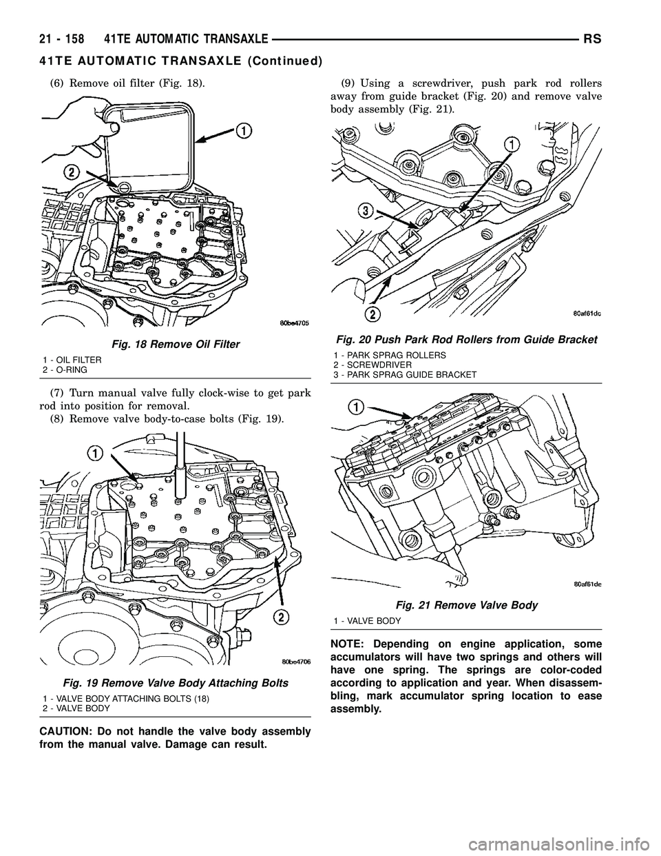
(6) Remove oil filter (Fig. 18).
(7) Turn manual valve fully clock-wise to get park
rod into position for removal.
(8) Remove valve body-to-case bolts (Fig. 19).
CAUTION: Do not handle the valve body assembly
from the manual valve. Damage can result.(9) Using a screwdriver, push park rod rollers
away from guide bracket (Fig. 20) and remove valve
body assembly (Fig. 21).
NOTE: Depending on engine application, some
accumulators will have two springs and others will
have one spring. The springs are color-coded
according to application and year. When disassem-
bling, mark accumulator spring location to ease
assembly.
Fig. 18 Remove Oil Filter
1 - OIL FILTER
2 - O-RING
Fig. 19 Remove Valve Body Attaching Bolts
1 - VALVE BODY ATTACHING BOLTS (18)
2 - VALVE BODY
Fig. 20 Push Park Rod Rollers from Guide Bracket
1 - PARK SPRAG ROLLERS
2 - SCREWDRIVER
3 - PARK SPRAG GUIDE BRACKET
Fig. 21 Remove Valve Body
1 - VALVE BODY
21 - 158 41TE AUTOMATIC TRANSAXLERS
41TE AUTOMATIC TRANSAXLE (Continued)
Page 1655 of 2339
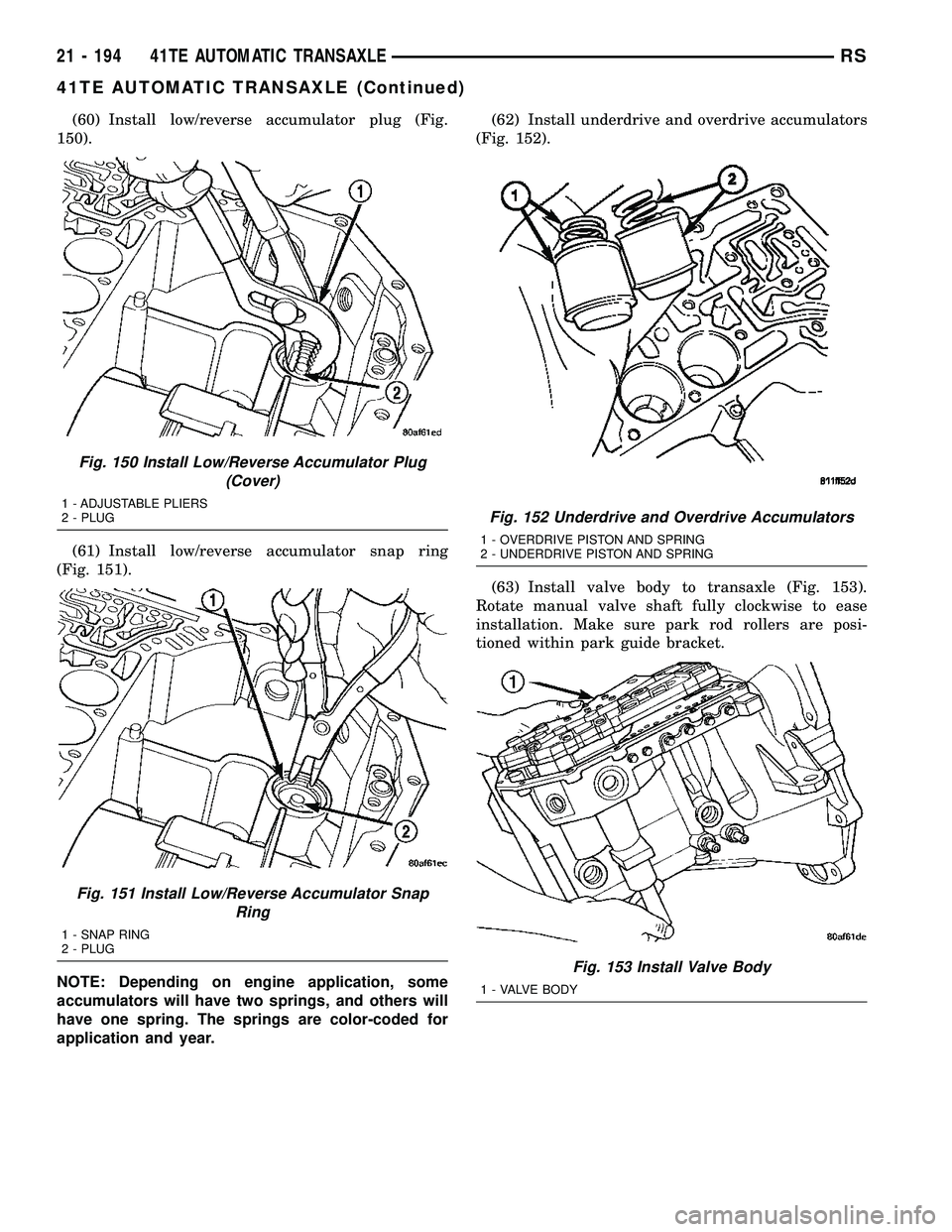
(60) Install low/reverse accumulator plug (Fig.
150).
(61) Install low/reverse accumulator snap ring
(Fig. 151).
NOTE: Depending on engine application, some
accumulators will have two springs, and others will
have one spring. The springs are color-coded for
application and year.(62) Install underdrive and overdrive accumulators
(Fig. 152).
(63) Install valve body to transaxle (Fig. 153).
Rotate manual valve shaft fully clockwise to ease
installation. Make sure park rod rollers are posi-
tioned within park guide bracket.
Fig. 150 Install Low/Reverse Accumulator Plug
(Cover)
1 - ADJUSTABLE PLIERS
2 - PLUG
Fig. 151 Install Low/Reverse Accumulator Snap
Ring
1 - SNAP RING
2 - PLUG
Fig. 152 Underdrive and Overdrive Accumulators
1 - OVERDRIVE PISTON AND SPRING
2 - UNDERDRIVE PISTON AND SPRING
Fig. 153 Install Valve Body
1 - VALVE BODY
21 - 194 41TE AUTOMATIC TRANSAXLERS
41TE AUTOMATIC TRANSAXLE (Continued)
Page 1743 of 2339
OPERATION
The Transmission Range Sensor (TRS) (Fig. 331)
communicates shift lever position (SLP) to the PCM/
TCM as a combination of open and closed switches.
Each shift lever position has an assigned combina-
tion of switch states (open/closed) that the PCM/TCM
receives from four sense circuits. The PCM/TCM
interprets this information and determines the
appropriate transaxle gear position and shift sched-
ule.
Since there are four switches, there are 16 possible
combinations of open and closed switches (codes).
Seven of these codes are related to gear position and
three are recognized as ªbetween gearº codes. This
results in six codes which should never occur. These
are called ªinvalidº codes. An invalid code will result
in a DTC, and the PCM/TCM will then determine the
shift lever position based on pressure switch data.
This allows reasonably normal transmission opera-
tion with a TRS failure.
TRS SWITCH STATES
SLP T42 T41 T3 T1
PCL CL CL OP
RCL OP OP OP
NCL CL OP CL
ODOP OP OP CL
3OP OP CL OP
LCL OP CL CL
TRANSMISSION TEMPERATURE SENSOR
The TRS has an integrated thermistor (Fig. 332)
that the PCM/TCM uses to monitor the transmis-
sion's sump temperature. Since fluid temperature
can affect transmission shift quality and convertor
lock up, the PCM/TCM requires this information to
determine which shift schedule to operate in. The
PCM also monitors this temperature data so it can
energize the vehicle cooling fan(s) when a transmis-
sion ªoverheatº condition exists. If the thermistor cir-
cuit fails, the PCM/TCM will revert to calculated oil
temperature usage.
CALCULATED TEMPERATURE
A failure in the temperature sensor or circuit will
result in calculated temperature being substituted for
actual temperature. Calculated temperature is a pre-dicted fluid temperature which is calculated from a
combination of inputs:
²Battery (ambient) temperature
²Engine coolant temperature
²In-gear run time since start-up
REMOVAL
(1) Remove valve body assembly from transaxle.
(Refer to 21 - TRANSMISSION/TRANSAXLE/AUTO-
MATIC - 41TE/VALVE BODY - REMOVAL)
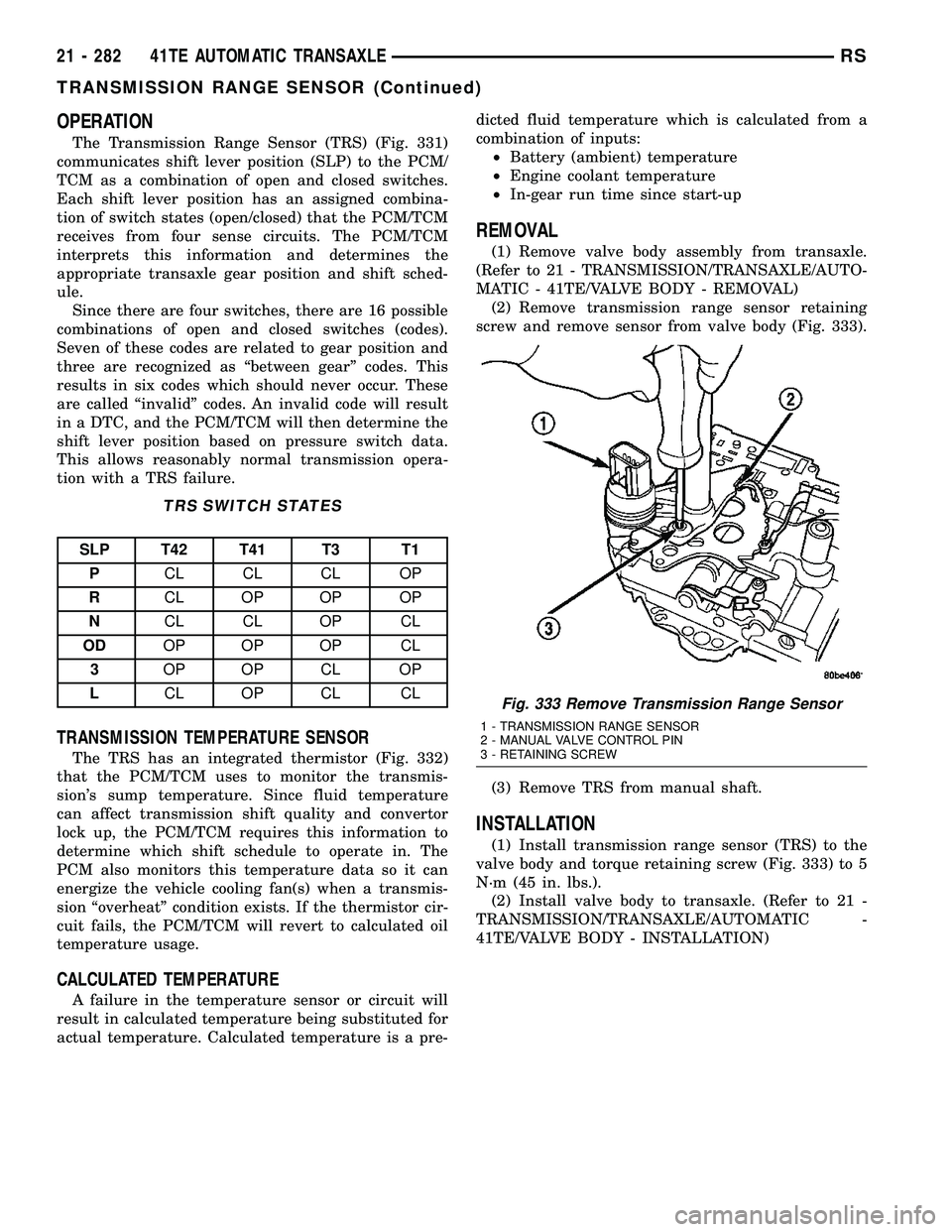
(2) Remove transmission range sensor retaining
screw and remove sensor from valve body (Fig. 333).
(3) Remove TRS from manual shaft.
INSTALLATION
(1) Install transmission range sensor (TRS) to the
valve body and torque retaining screw (Fig. 333) to 5
N´m (45 in. lbs.).
(2) Install valve body to transaxle. (Refer to 21 -
TRANSMISSION/TRANSAXLE/AUTOMATIC -
41TE/VALVE BODY - INSTALLATION)
Fig. 333 Remove Transmission Range Sensor
1 - TRANSMISSION RANGE SENSOR
2 - MANUAL VALVE CONTROL PIN
3 - RETAINING SCREW
21 - 282 41TE AUTOMATIC TRANSAXLERS
TRANSMISSION RANGE SENSOR (Continued)
Page 1780 of 2339
BODY
TABLE OF CONTENTS
page page
BODY
DESCRIPTION - VEHICLE IDENTIFICATION....1
WARNING
SAFETY PRECAUTIONS AND WARNINGS . . . 1
DIAGNOSIS AND TESTING
WATER LEAKS........................1
WIND NOISE..........................2
STANDARD PROCEDURE
STANDARD PROCEDURE - PLASTIC BODY
PANEL REPAIR........................3
STANDARD PROCEDURE - HEAT STAKING . . 9
SPECIFICATIONS
TORQUE............................10
BODY LUBRICATION...................12
SPECIAL TOOLS
BODY..............................13DOOR - FRONT.........................14
DOORS - SLIDING.......................24
DECKLID/HATCH/LIFTGATE/TAILGATE.......40
EXTERIOR.............................45
HOOD.................................62
INSTRUMENT PANEL.....................65
INTERIOR..............................78
PAINT................................100
SEATS...............................102
STATIONARY GLASS....................161
WEATHERSTRIP/SEALS..................166
SUNROOF.............................169
BODY STRUCTURE.....................177
BODY
DESCRIPTION - VEHICLE IDENTIFICATION
Throughout this group, references to the
DaimlerChrysler Corporation vehicle family identifi-
cation code are used when describing a procedure
that is unique to that vehicle. Refer to Introduction
Group of this manual for detailed information on
vehicle identification. If a procedure is common to all
vehicles covered in this manual, no reference will be
made to a vehicle family code.
WARNING
SAFETY PRECAUTIONS AND WARNINGS
WARNING: USE A OSHA APPROVED BREATHING
FILTER WHEN SPRAYING PAINT OR SOLVENTS IN
A CONFINED AREA. PERSONAL INJURY CAN
RESULT.
AVOID PROLONGED SKIN CONTACT WITH PETRO-
LEUM OR ALCOHOL ± BASED CLEANING SOL-
VENTS. PERSONAL INJURY CAN RESULT.
DO NOT STAND UNDER A HOISTED VEHICLE THAT
IS NOT PROPERLY SUPPORTED ON SAFETY
STANDS. PERSONAL INJURY CAN RESULT.
CAUTION: When holes must be drilled or punched
in an inner body panel, verify depth of space to the
outer body panel, electrical wiring, or other compo-nents. Damage to vehicle can result.
Do not weld exterior panels unless combustible
material on the interior of vehicle is removed from
the repair area. Fire or hazardous conditions, can
result.
Always have a fire extinguisher ready for use when
welding.
Disconnect the negative (-) cable clamp from the
battery when servicing electrical components that
are live when the ignition is OFF. Damage to electri-
cal system can result.
Do not use abrasive chemicals or compounds on
painted surfaces. Damage to finish can result.
Do not use harsh alkaline based cleaning solvents
on painted or upholstered surfaces. Damage to fin-
ish or color can result.
Do not hammer or pound on plastic trim panel
when servicing interior trim. Plastic panels can
break.
DIAGNOSIS AND TESTING
WATER LEAKS
Water leaks can be caused by poor sealing,
improper body component alignment, body seam
porosity, missing plugs, or blocked drain holes. Cen-
trifugal and gravitational force can cause water to
drip from a location away from the actual leak point,
making leak detection difficult. All body sealing
points should be water tight in normal wet-driving
conditions. Water flowing downward from the front of
RSBODY23-1
Page 1784 of 2339
CODE FAMILY NAME COMMON TRADE NAME TYPICAL APPLICATION
UP UNSATURATED
POLYESTER
(THERMOSETTING)SMC, BMC, TMC, ZMC, IMC,
XSMC, UPGRILLE OPENING PANEL,
LIFTGATES, FLARESIDE
FENDERS, FENDER
EXTENSIONS
EEBC ETHER/ESTER BLOCKED
CO-POLYMEREEBC BUMPERS
EEBC/PBTP EEBC/POLYBUTYLENE
TEREPTHALATEEEBC, PBTP, BEXLOY BUMPER, ROCKER PANELS
EMPP ETHYLENE MODIFIED
POLYPROPYLENEEMPP BUMPER COVERS
EPDM ETHYLENE/
PROPROPYLENE DIENE
MONOMEREPDM, NORDEL, VISTALON BUMPERS
EPM ETHYLENE/
PROPROPYLENE CO-
POLYMEREPM FENDERS
MPU FOAM POLYURETHANE MPU SPOILERS
PE POLYETHYLENE ALATHON, DYLAN,
LUPOLEN, MARLEX-
PP POLYPROPYLENE
(BLENDS)NORYL, AZDEL, MARLOX,
DYLON, PRAVEXINNER FENDER, SPOILERS,
KICK PANELS,A-PILLARS,
DOOR PANELS, B-PILLARS,
QUARTER PANELS, SPORT
BAR TRIM, LIFTGATE TRIM,
DECKLID TRIM SCUFF
PLATES, KICK PANELS,
CONSOLES
PP/EPDM PP/EPDM ALLOY PP/EPDM SPOILERS, GRILLES
PUR POLYURETHANE COLONELS, PUR, PU FASCIAS, BUMPERS
PUR/PC PUR/PC ALLOY TEXIN BUMPERS
PVC POLYVINYL CHLORIDE APEX, GEON, VINYLITE BODY MOLDINGS, WIRE
INSULATION, STEERING
WHEELS
RIM REACTION INJECTED
MOLDED POLYURETHANERIM, BAYFLEX FRONT FASCIAS, MODULAR
WINDOWS
RRIM REINFORCED REACTION
INJECTED MOLDEDPUR, RRIM FASCIAS, BODY PANELS,
BODY TRIMS
TPE THERMO POLYETHYLENE TPE, HYTREL, BEXLOY-V FASCIAS, BUMPERS,
CLADDINGS
TPO THERMOPOLYOLEFIN POLYTROPE, RENFLEX,
SANTOPRENE, VISAFLEX,
ETA, APEX, TPO, SHIELDS,
CLADDINGSBUMPERS, END CAPS,
TELCAR, RUBBER, STRIPS,
SIGHT, INTERIOR B POST
TPP THERMO-POLYPROPYLENE TPP BUMPERS
TPU THERMOPOLYURETHANE,
POLYESTERTPU, HYTREL, TEXIN,
ESTANEBUMPERS, BODY SIDE,
MOLDINGS, FENDERS,
FASCIAS
RSBODY23-5
BODY (Continued)