2005 CHRYSLER VOYAGER air filter
[x] Cancel search: air filterPage 1315 of 2339
RIGHT MOUNT
REMOVAL
(1) Remove air cleaner housing lid and clean air
hose from throttle body.
(2) Remove air cleaner element and housing.
(3) Disconnect make-up air hose from cylinder
head cover.
(4) Remove the load on the right engine mount by
carefully supporting the engine assembly with a floor
jack.
(5) Disconnect electrical harness support clips from
engine mount bracket.
(6) Remove the bolts attaching the engine mount
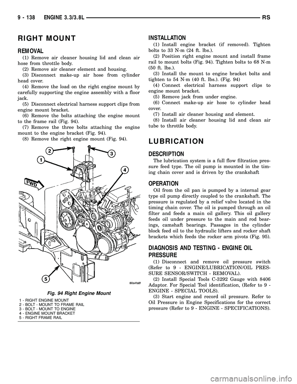
to the frame rail (Fig. 94).
(7) Remove the three bolts attaching the engine
mount to the engine bracket (Fig. 94).
(8) Remove the right engine mount (Fig. 94).
INSTALLATION
(1) Install engine bracket (if removed). Tighten
bolts to 33 N´m (24 ft. lbs.).
(2) Position right engine mount and install frame
rail to mount bolts (Fig. 94). Tighten bolts to 68 N´m
(50 ft. lbs.).
(3) Install the mount to engine bracket bolts and
tighten to 54 N´m (40 ft. lbs.). (Fig. 94)
(4) Connect electrical harness support clips to
engine mount bracket.
(5) Remove jack from under engine.
(6) Connect make-up air hose to cylinder head
cover.
(7) Install air cleaner housing and element.
(8) Install air cleaner housing lid and clean air
tube to throttle body.
LUBRICATION
DESCRIPTION
The lubrication system is a full flow filtration pres-
sure feed type. The oil pump is mounted in the tim-
ing chain cover and is driven by the crankshaft
OPERATION
Oil from the oil pan is pumped by a internal gear
type oil pump directly coupled to the crankshaft. The
pressure is regulated by a relief valve located in the
timing chain cover. The oil is pumped through an oil
filter and feeds a main oil gallery. This oil gallery
feeds oil under pressure to the main and rod bear-
ings, camshaft bearings. Passages in the cylinder
block feed oil to the hydraulic lifters and rocker shaft
brackets which feeds the rocker arm pivots (Fig. 95).
DIAGNOSIS AND TESTING - ENGINE OIL
PRESSURE
(1) Disconnect and remove oil pressure switch
(Refer to 9 - ENGINE/LUBRICATION/OIL PRES-
SURE SENSOR/SWITCH - REMOVAL).
(2) Install Special Tools C-3292 Gauge with 8406
Adaptor. For Special Tool identification, (Refer to 9 -
ENGINE - SPECIAL TOOLS).
(3) Start engine and record oil pressure. Refer to
Oil Pressure in Engine Specifications for the correct
pressure (Refer to 9 - ENGINE - SPECIFICATIONS).
Fig. 94 Right Engine Mount
1 - RIGHT ENGINE MOUNT
2 - BOLT - MOUNT TO FRAME RAIL
3 - BOLT - MOUNT TO ENGINE
4 - ENGINE MOUNT BRACKET
5 - RIGHT FRAME RAIL
9 - 138 ENGINE 3.3/3.8LRS
Page 1404 of 2339
(2) Install sensor and tighten to 27 N´m (20 ft.
lbs.) (Fig. 23).
(3) Connect the electrical connector for the O2 sen-
sor and install onto bracket.
(4) Lower vehicle.
(5) Connect the negative battery cable.
INSTALLATION - UPSTREAM 1/1 - 3.3/3.8L
The engines uses two heated oxygen sensors.
(1) After removing the sensor, the exhaust mani-
fold threads must be cleaned with an 18 mm X 1.5 +
6E tap. If reusing the original sensor, coat the sensor
threads with an anti-seize compound such as Loctite
771- 64 or equivalent. New sensors have compound
on the threads and do not require an additional coat-
ing.
(2) Install sensor and tighten to 27 N´m (20 ft.
lbs.).
(3) Connect the electrical connector for the O2 sen-
sor and install onto bracket.
(4) Connect the electrical connector for the speed
control servo.
(5) Install the speed control servo and bracket
refer to the Speed Control Servo for more informa-
tion.
(6) Connect the speed control vacuum harness to
servo.
(7) Install the battery tray, refer to the Battery
section for more information.
(8) Install battery, refer to the Battery section for
more information.
INSTALLATION DOWNSTREAM 2/1 -
2.4/3.3/3.8L
The O2S is located on the side of the catalytic con-
verter.
Threads of new oxygen sensors are factory coated
with anti-seize compound to aid in removal.DO
NOT add any additional anti-seize compound to
the threads of a new oxygen sensor.
(1) Install sensor and tighten to 27 N´m (20 ft.
lbs.).
(2) Connect the electrical connector.
(3) Lower vehicle.
(4) Install the negative battery cable.
THROTTLE BODY
DESCRIPTION
The throttle body is located on the intake manifold
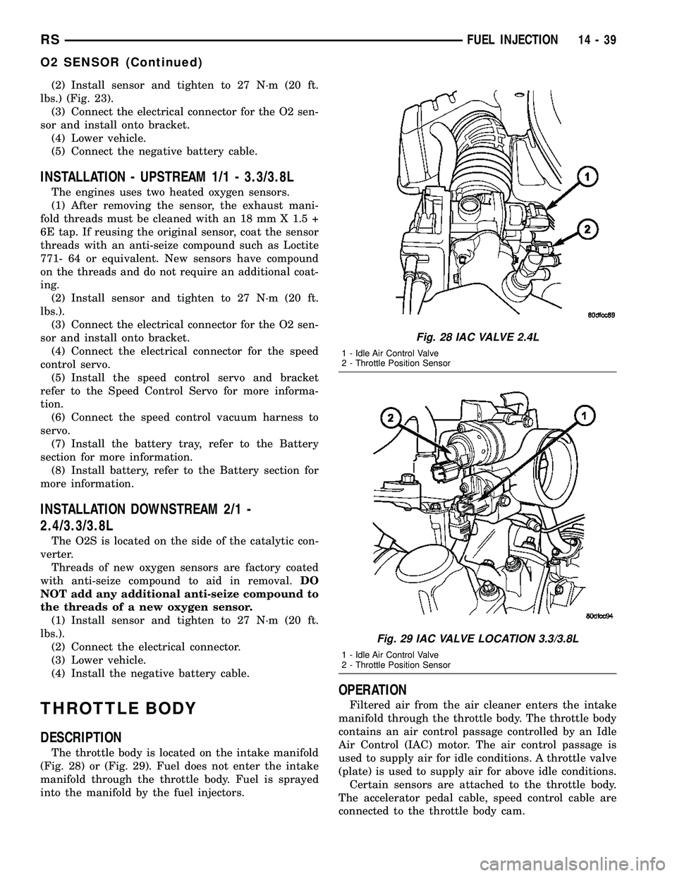
(Fig. 28) or (Fig. 29). Fuel does not enter the intake
manifold through the throttle body. Fuel is sprayed
into the manifold by the fuel injectors.
OPERATION
Filtered air from the air cleaner enters the intake
manifold through the throttle body. The throttle body
contains an air control passage controlled by an Idle
Air Control (IAC) motor. The air control passage is
used to supply air for idle conditions. A throttle valve
(plate) is used to supply air for above idle conditions.
Certain sensors are attached to the throttle body.
The accelerator pedal cable, speed control cable are
connected to the throttle body cam.
Fig. 28 IAC VALVE 2.4L
1 - Idle Air Control Valve
2 - Throttle Position Sensor
Fig. 29 IAC VALVE LOCATION 3.3/3.8L
1 - Idle Air Control Valve
2 - Throttle Position Sensor
RSFUEL INJECTION14-39
O2 SENSOR (Continued)
Page 1462 of 2339
TRANSMISSION/TRANSAXLE
TABLE OF CONTENTS
page page
40TE AUTOMATIC TRANSAXLE..............141TE AUTOMATIC TRANSAXLE............146
40TE AUTOMATIC TRANSAXLE
TABLE OF CONTENTS
page page
40TE AUTOMATIC TRANSAXLE
DESCRIPTION..........................2
OPERATION............................4
DIAGNOSIS AND TESTING
DIAGNOSIS AND TESTING - 4XTE
TRANSAXLE GENERAL DIAGNOSIS........5
DIAGNOSIS AND TESTING - ROAD TEST....5
DIAGNOSIS AND TESTING - HYDRAULIC
PRESSURE TESTS.....................6
DIAGNOSIS AND TESTING - CLUTCH AIR
PRESSURE TESTS.....................8
DIAGNOSIS AND TESTING - TORQUE
CONVERTER HOUSING FLUID LEAKAGE....9
REMOVAL.............................9
DISASSEMBLY.........................12
ASSEMBLY............................29
INSTALLATION.........................51
SCHEMATICS AND DIAGRAMS
4XTE TRANSAXLE HYDRAULIC
SCHEMATICS........................54
SPECIFICATIONS - 41TE TRANSAXLE.......66
SPECIAL TOOLS.......................68
ACCUMULATOR
DESCRIPTION.........................73
OPERATION...........................73
DRIVING CLUTCHES
DESCRIPTION.........................74
OPERATION...........................74
FINAL DRIVE
DESCRIPTION.........................74
OPERATION...........................75
DISASSEMBLY.........................75
ASSEMBLY............................78
ADJUSTMENTS
DIFFERENTIAL BEARING PRELOAD
MEASUREMENT AND ADJUSTMENT......79FLUID
STANDARD PROCEDURE
FLUID LEVEL AND CONDITION CHECK....82
STANDARD PROCEDURE - FLUID AND
FILTER SERVICE......................82
GEAR SHIFT CABLE
REMOVAL.............................84
HOLDING CLUTCHES
DESCRIPTION.........................86
OPERATION...........................86
INPUT CLUTCH ASSEMBLY
DISASSEMBLY.........................86
ASSEMBLY............................95
OIL PUMP
DESCRIPTION........................110
OPERATION..........................110
DISASSEMBLY........................110
ASSEMBLY...........................112
PLANETARY GEARTRAIN
DESCRIPTION........................112
OPERATION..........................112
SEAL - OIL PUMP
REMOVAL............................113
INSTALLATION........................113
SHIFT INTERLOCK SOLENOID
DESCRIPTION........................113
OPERATION..........................114
DIAGNOSIS AND TESTING - BRAKE/
TRANSMISSION SHIFT INTERLOCK
SOLENOID..........................115
REMOVAL............................115
INSTALLATION........................116
SOLENOID/PRESSURE SWITCH ASSY
DESCRIPTION........................117
OPERATION..........................118
REMOVAL............................118
INSTALLATION........................119
RSTRANSMISSION/TRANSAXLE21-1
Page 1543 of 2339
FLUID
STANDARD PROCEDURE
FLUID LEVEL AND CONDITION CHECK
NOTE: Only transmission fluid of the type labeled
Mopar ATF+4 (Automatic Transmission Fluid)
should be used in this transaxle.
FLUID LEVEL CHECK
The transmission sump has a fluid level indicator
(dipstick) to check oil similar to most automatic
transmissions. It is located on the left side of the
engine. Be sure to wipe all dirt from dipstick handle
before removing.
The torque converter fills in both the P Park and N
Neutral positions. Place the selector lever in P Park
to be sure that the fluid level check is accurate.The
engine should be running at idle speed for at
least one minute, with the vehicle on level
ground.At normal operating temperature 82É C
(180É F), the fluid level is correct if it is in the HOT
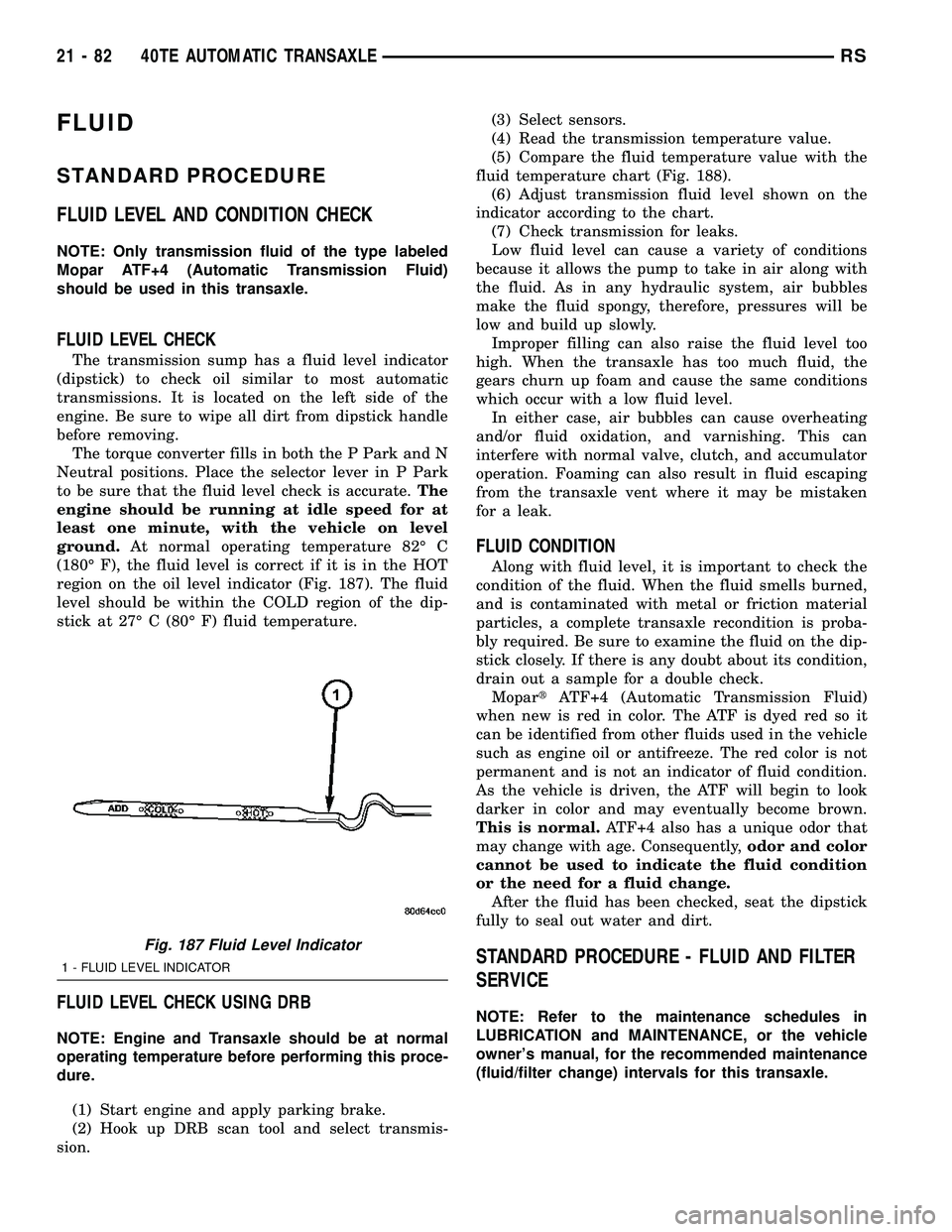
region on the oil level indicator (Fig. 187). The fluid
level should be within the COLD region of the dip-
stick at 27É C (80É F) fluid temperature.
FLUID LEVEL CHECK USING DRB
NOTE: Engine and Transaxle should be at normal
operating temperature before performing this proce-
dure.
(1) Start engine and apply parking brake.
(2) Hook up DRB scan tool and select transmis-
sion.(3) Select sensors.
(4) Read the transmission temperature value.
(5) Compare the fluid temperature value with the
fluid temperature chart (Fig. 188).
(6) Adjust transmission fluid level shown on the
indicator according to the chart.
(7) Check transmission for leaks.
Low fluid level can cause a variety of conditions
because it allows the pump to take in air along with
the fluid. As in any hydraulic system, air bubbles
make the fluid spongy, therefore, pressures will be
low and build up slowly.
Improper filling can also raise the fluid level too
high. When the transaxle has too much fluid, the
gears churn up foam and cause the same conditions
which occur with a low fluid level.
In either case, air bubbles can cause overheating
and/or fluid oxidation, and varnishing. This can
interfere with normal valve, clutch, and accumulator
operation. Foaming can also result in fluid escaping
from the transaxle vent where it may be mistaken
for a leak.
FLUID CONDITION
Along with fluid level, it is important to check the
condition of the fluid. When the fluid smells burned,
and is contaminated with metal or friction material
particles, a complete transaxle recondition is proba-
bly required. Be sure to examine the fluid on the dip-
stick closely. If there is any doubt about its condition,
drain out a sample for a double check.
MopartATF+4 (Automatic Transmission Fluid)
when new is red in color. The ATF is dyed red so it
can be identified from other fluids used in the vehicle
such as engine oil or antifreeze. The red color is not
permanent and is not an indicator of fluid condition.
As the vehicle is driven, the ATF will begin to look
darker in color and may eventually become brown.
This is normal.ATF+4 also has a unique odor that
may change with age. Consequently,odor and color
cannot be used to indicate the fluid condition
or the need for a fluid change.
After the fluid has been checked, seat the dipstick
fully to seal out water and dirt.
STANDARD PROCEDURE - FLUID AND FILTER
SERVICE
NOTE: Refer to the maintenance schedules in
LUBRICATION and MAINTENANCE, or the vehicle
owner's manual, for the recommended maintenance
(fluid/filter change) intervals for this transaxle.
Fig. 187 Fluid Level Indicator
1 - FLUID LEVEL INDICATOR
21 - 82 40TE AUTOMATIC TRANSAXLERS
Page 1607 of 2339
41TE AUTOMATIC TRANSAXLE
TABLE OF CONTENTS
page page
41TE AUTOMATIC TRANSAXLE
DESCRIPTION........................147
OPERATION..........................149
DIAGNOSIS AND TESTING
DIAGNOSIS AND TESTING - 4XTE
TRANSAXLE GENERAL DIAGNOSIS......149
DIAGNOSIS AND TESTING - ROAD TEST . . 150
DIAGNOSIS AND TESTING - HYDRAULIC
PRESSURE TESTS...................150
DIAGNOSIS AND TESTING - CLUTCH AIR
PRESSURE TESTS...................153
DIAGNOSIS AND TESTING - TORQUE
CONVERTER HOUSING FLUID LEAKAGE . . 154
REMOVAL............................154
DISASSEMBLY........................157
ASSEMBLY...........................174
INSTALLATION........................196
SCHEMATICS AND DIAGRAMS
4XTE TRANSAXLE HYDRAULIC
SCHEMATICS.......................199
SPECIFICATIONS - 41TE TRANSAXLE......211
SPECIAL TOOLS
41TE AUTOMATIC TRANSAXLE.........213
ACCUMULATOR
DESCRIPTION........................218
OPERATION..........................218
DRIVING CLUTCHES
DESCRIPTION........................219
OPERATION..........................219
FINAL DRIVE
DESCRIPTION........................219
OPERATION..........................220
DISASSEMBLY........................220
ASSEMBLY...........................224
ADJUSTMENTS
ADJUSTMENT - DIFFERENTIAL BEARING
PRELOAD..........................228
FLUID
STANDARD PROCEDURE
FLUID LEVEL AND CONDITION CHECK . . . 230
STANDARD PROCEDURE - FLUID AND
FILTER SERVICE.....................231
GEAR SHIFT CABLE
REMOVAL............................233
INSTALLATION........................234
ADJUSTMENTS
GEARSHIFT CABLE ADJUSTMENT.......235
HOLDING CLUTCHES
DESCRIPTION........................236
OPERATION..........................236INPUT CLUTCH ASSEMBLY
DISASSEMBLY........................237
ASSEMBLY...........................246
OIL PUMP
DESCRIPTION........................261
OPERATION..........................261
DISASSEMBLY........................261
ASSEMBLY...........................263
PLANETARY GEARTRAIN
DESCRIPTION........................263
OPERATION..........................263
SEAL - OIL PUMP
REMOVAL............................264
INSTALLATION........................264
SHIFT INTERLOCK SOLENOID
DESCRIPTION........................264
OPERATION..........................265
DIAGNOSIS AND TESTING - BRAKE/
TRANSMISSION SHIFT INTERLOCK
SOLENOID..........................266
REMOVAL............................266
INSTALLATION........................267
SOLENOID/PRESSURE SWITCH ASSY
DESCRIPTION........................268
OPERATION..........................268
REMOVAL............................269
INSTALLATION........................270
SPEED SENSOR - INPUT
DESCRIPTION........................271
OPERATION..........................271
REMOVAL............................272
INSTALLATION........................272
SPEED SENSOR - OUTPUT
DESCRIPTION........................273
OPERATION..........................273
REMOVAL............................274
INSTALLATION........................274
TORQUE CONVERTER
DESCRIPTION........................275
OPERATION..........................278
REMOVAL............................280
INSTALLATION........................280
TRANSMISSION CONTROL RELAY
DESCRIPTION........................281
OPERATION..........................281
TRANSMISSION RANGE SENSOR
DESCRIPTION........................281
OPERATION..........................282
REMOVAL............................282
INSTALLATION........................282
21 - 146 41TE AUTOMATIC TRANSAXLERS
Page 1780 of 2339
BODY
TABLE OF CONTENTS
page page
BODY
DESCRIPTION - VEHICLE IDENTIFICATION....1
WARNING
SAFETY PRECAUTIONS AND WARNINGS . . . 1
DIAGNOSIS AND TESTING
WATER LEAKS........................1
WIND NOISE..........................2
STANDARD PROCEDURE
STANDARD PROCEDURE - PLASTIC BODY
PANEL REPAIR........................3
STANDARD PROCEDURE - HEAT STAKING . . 9
SPECIFICATIONS
TORQUE............................10
BODY LUBRICATION...................12
SPECIAL TOOLS
BODY..............................13DOOR - FRONT.........................14
DOORS - SLIDING.......................24
DECKLID/HATCH/LIFTGATE/TAILGATE.......40
EXTERIOR.............................45
HOOD.................................62
INSTRUMENT PANEL.....................65
INTERIOR..............................78
PAINT................................100
SEATS...............................102
STATIONARY GLASS....................161
WEATHERSTRIP/SEALS..................166
SUNROOF.............................169
BODY STRUCTURE.....................177
BODY
DESCRIPTION - VEHICLE IDENTIFICATION
Throughout this group, references to the
DaimlerChrysler Corporation vehicle family identifi-
cation code are used when describing a procedure
that is unique to that vehicle. Refer to Introduction
Group of this manual for detailed information on
vehicle identification. If a procedure is common to all
vehicles covered in this manual, no reference will be
made to a vehicle family code.
WARNING
SAFETY PRECAUTIONS AND WARNINGS
WARNING: USE A OSHA APPROVED BREATHING
FILTER WHEN SPRAYING PAINT OR SOLVENTS IN
A CONFINED AREA. PERSONAL INJURY CAN
RESULT.
AVOID PROLONGED SKIN CONTACT WITH PETRO-
LEUM OR ALCOHOL ± BASED CLEANING SOL-
VENTS. PERSONAL INJURY CAN RESULT.
DO NOT STAND UNDER A HOISTED VEHICLE THAT
IS NOT PROPERLY SUPPORTED ON SAFETY
STANDS. PERSONAL INJURY CAN RESULT.
CAUTION: When holes must be drilled or punched
in an inner body panel, verify depth of space to the
outer body panel, electrical wiring, or other compo-nents. Damage to vehicle can result.
Do not weld exterior panels unless combustible
material on the interior of vehicle is removed from
the repair area. Fire or hazardous conditions, can
result.
Always have a fire extinguisher ready for use when
welding.
Disconnect the negative (-) cable clamp from the
battery when servicing electrical components that
are live when the ignition is OFF. Damage to electri-
cal system can result.
Do not use abrasive chemicals or compounds on
painted surfaces. Damage to finish can result.
Do not use harsh alkaline based cleaning solvents
on painted or upholstered surfaces. Damage to fin-
ish or color can result.
Do not hammer or pound on plastic trim panel
when servicing interior trim. Plastic panels can
break.
DIAGNOSIS AND TESTING
WATER LEAKS
Water leaks can be caused by poor sealing,
improper body component alignment, body seam
porosity, missing plugs, or blocked drain holes. Cen-
trifugal and gravitational force can cause water to
drip from a location away from the actual leak point,
making leak detection difficult. All body sealing
points should be water tight in normal wet-driving
conditions. Water flowing downward from the front of
RSBODY23-1
Page 2154 of 2339
²a rotary adjustment knob for temperature.
²a rotary adjustment for fan speed control.
AUTOMATIC TEMPERATURE CONTROL
Two different automatic temperature control (ATC)
heating-A/C systems are available for this model
depending on the market.
The Dual-Zone ATC system allows the driver and
front occupants to each select individual comfort tem-
peratures.
The Three-Zone ATC system allows both the driver
and front occupants and the rear intermediate occu-
pants to select individual comfort temperatures.
NOTE: Individual comfort temperatures are the per-
ceived temperature level at the individual seating
areas, NOT the actual passenger compartment air
temperature.
The ATC system includes a particulate air filter.
The filter element is the same size as the A/C evap-
orator to ensure ample capacity. A door at the base of
the HVAC housing below the glove box provides easy
access to the filter element.
The ATC computer utilizes integrated circuitry and
information carried on the programmable communi-
cations interface (PCI) data bus network to monitor
many sensors and switch inputs throughout the vehi-
cle. In response to those inputs, the internal circuitry
and programming of the ATC computer allow it to
control electronic functions and features of the ATC
system. The inputs to the ATC computer are:
²Vehicle Speed/Engine RPM± The ATC com-
puter monitors engine rpm, vehicle speed and mani-
fold absolute pressure information from the
powertrain control module (PCM).
²Coolant Temperature± ATC computer moni-
tors coolant temperature received from the PCM and
converts it to degrees Fahrenheit.
²Ambient Temperature± ATC computer moni-
tors ambient temperature from the compass mini trip
computer (CMTC) and converts it to degrees Fahren-
heit.
²Engine Miscellaneous Sensor Status±ATC
computer monitors A/C disable information from the
PCM.
²Refrigerant Pressure± ATC computer moni-
tors barometric pressure, intake air temperature,
high side pressure and methanol content as broad-
cast by the PCM.
²Door Ajar Status± The ATC computer moni-
tors driver front door, passenger front door, left rear
door, right rear door and liftgate ajar information, as
identified by the body control module (BCM), to
determine if all in-car temperatures should be main-
tained.²Dimming± The ATC computer monitors dim-
ming status from the BCM to determine the required
level of brightness and will dim accordingly.
²Vehicle Odometer± The ATC computer moni-
tors the vehicle odometer information from the BCM
to prevent flashing the vacuum-flourescent (VF) dig-
ital display icons if the manual motor calibration or
manual cool down tests have failed. Flashing of the
display icons will cease when the vehicle odometer is
greater than 3 miles.
²English/Metric± The ATC computer monitors
the English/Metric information broadcast by the
CMTC. The set temp displays for both the front and
rear control heads will be set accordingly.
²Vehicle Identification Number± The ATC
computer monitors the last eight characters of the
VIN broadcast by the PCM and compares it to the
information stored in EEPROM. If it is different, the
new number will be stored over the old one and a
motor calibration shall be initiated.
²A/C System Information± The ATC computer
will send a message for evaporator temperature too
low, fan blower relay status, evaporator sensor fail-
ure, rear window defogger relay and A/C select.
FRONT CONTROL PANEL
The front A/C-heater control and integral computer
is mounted in the instrument panel and contains:
²a power button which allows the system to be
completely turned off. The display is blank when the
system is off.
²a rocker switch that selects a cool-down rate.
LO-AUTO or HI-AUTO are displayed when the sys-
tem is in automatic operation.
²three rocker switches that select comfort temper-
atures from 15É to 30É C (59É to 85É F), which are
shown in the VF digital display. If the set temp is 15É
C (59É F) and the down button is pressed, the set
temp value will become 13É C (55É F) but the display
will show LO. If the set temp is 29É C (85É F) and the
up button is pressed, the set temp value will become
32É C (90É F) but the display will show HIGH. Tem-
peratures can be displayed in either metric or Fahr-
enheit, which is controlled from the overhead console.
²an air conditioning button that allows the com-
pressor to be turned off. A Snowflake symbol is illu-
minated when air conditioning is on, whether under
manual or automatic control.
²an air recirculation button. A Recirculation sym-
bol appears in the display when the button is
pressed, or when the system exceeds 80 percent recir-
culated air under automatic control due to high air
conditioning demand.
²a rear window defogger on/off switch. A graphic
symbol shows when the defroster is on.
RSHEATING & AIR CONDITIONING24-3
HEATING & AIR CONDITIONING (Continued)
Page 2193 of 2339
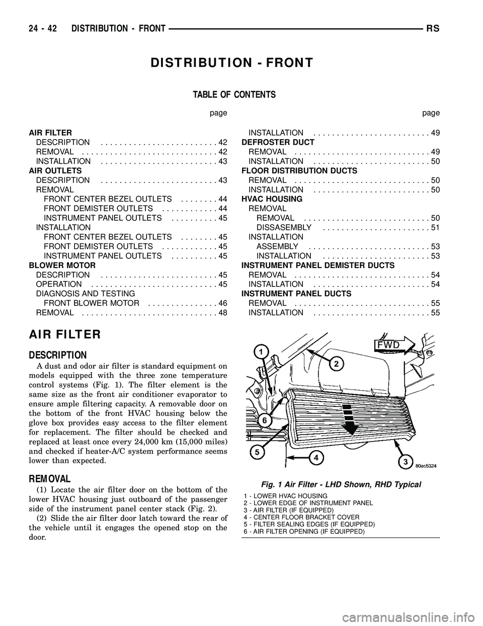
DISTRIBUTION - FRONT
TABLE OF CONTENTS
page page
AIR FILTER
DESCRIPTION.........................42
REMOVAL.............................42
INSTALLATION.........................43
AIR OUTLETS
DESCRIPTION.........................43
REMOVAL
FRONT CENTER BEZEL OUTLETS........44
FRONT DEMISTER OUTLETS............44
INSTRUMENT PANEL OUTLETS..........45
INSTALLATION
FRONT CENTER BEZEL OUTLETS........45
FRONT DEMISTER OUTLETS............45
INSTRUMENT PANEL OUTLETS..........45
BLOWER MOTOR
DESCRIPTION.........................45
OPERATION...........................45
DIAGNOSIS AND TESTING
FRONT BLOWER MOTOR...............46
REMOVAL.............................48INSTALLATION.........................49
DEFROSTER DUCT
REMOVAL.............................49
INSTALLATION.........................50
FLOOR DISTRIBUTION DUCTS
REMOVAL.............................50
INSTALLATION.........................50
HVAC HOUSING
REMOVAL
REMOVAL...........................50
DISSASEMBLY.......................51
INSTALLATION
ASSEMBLY..........................53
INSTALLATION.......................53
INSTRUMENT PANEL DEMISTER DUCTS
REMOVAL.............................54
INSTALLATION.........................54
INSTRUMENT PANEL DUCTS
REMOVAL.............................55
INSTALLATION.........................55
AIR FILTER
DESCRIPTION
A dust and odor air filter is standard equipment on
models equipped with the three zone temperature
control systems (Fig. 1). The filter element is the
same size as the front air conditioner evaporator to
ensure ample filtering capacity. A removable door on
the bottom of the front HVAC housing below the
glove box provides easy access to the filter element
for replacement. The filter should be checked and
replaced at least once every 24,000 km (15,000 miles)
and checked if heater-A/C system performance seems
lower than expected.
REMOVAL
(1) Locate the air filter door on the bottom of the
lower HVAC housing just outboard of the passenger
side of the instrument panel center stack (Fig. 2).
(2) Slide the air filter door latch toward the rear of
the vehicle until it engages the opened stop on the
door.Fig. 1 Air Filter - LHD Shown, RHD Typical
1 - LOWER HVAC HOUSING
2 - LOWER EDGE OF INSTRUMENT PANEL
3 - AIR FILTER (IF EQUIPPED)
4 - CENTER FLOOR BRACKET COVER
5 - FILTER SEALING EDGES (IF EQUIPPED)
6 - AIR FILTER OPENING (IF EQUIPPED)
24 - 42 DISTRIBUTION - FRONTRS