2005 CHRYSLER VOYAGER wipers
[x] Cancel search: wipersPage 1283 of 2339
CYLINDER HEAD COVER -
RIGHT
REMOVAL
(1) Disconnect negative cable from battery.
(2) Remove the wiper module. (Refer to 8 - ELEC-
TRICAL/WIPERS/WASHERS/WIPER MODULE -
REMOVAL)
(3) Disconnect spark plug wires from plugs.
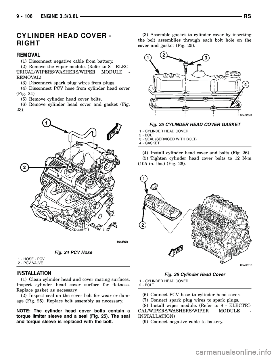
(4) Disconnect PCV hose from cylinder head cover
(Fig. 24).
(5) Remove cylinder head cover bolts.
(6) Remove cylinder head cover and gasket (Fig.
23).
INSTALLATION
(1) Clean cylinder head and cover mating surfaces.
Inspect cylinder head cover surface for flatness.
Replace gasket as necessary.
(2) Inspect seal on the cover bolt for wear or dam-
age (Fig. 25). Replace bolt assembly as necessary.
NOTE: The cylinder head cover bolts contain a
torque limiter sleeve and a seal (Fig. 25). The seal
and torque sleeve is replaced with the bolt.(3) Assemble gasket to cylinder cover by inserting
the bolt assemblies through each bolt hole on the
cover and gasket (Fig. 25).
(4) Install cylinder head cover and bolts (Fig. 26).
(5) Tighten cylinder head cover bolts to 12 N´m
(105 in. lbs.) (Fig. 26).
(6) Connect PCV hose to cylinder head cover.
(7) Connect spark plug wires to spark plugs.
(8) Install wiper module. (Refer to 8 - ELECTRI-
CAL/WIPERS/WASHERS/WIPER MODULE -
INSTALLATION)
(9) Connect negative cable to battery.
Fig. 24 PCV Hose
1 - HOSE - PCV
2 - P C V VA LV E
Fig. 25 CYLINDER HEAD COVER GASKET
1 - CYLINDER HEAD COVER
2 - BOLT
3 - SEAL (SERVICED WITH BOLT)
4 - GASKET
Fig. 26 Cylinder Head Cover
1 - CYLINDER HEAD COVER
2 - BOLT
9 - 106 ENGINE 3.3/3.8LRS
Page 1329 of 2339

(9) Install the upper intake manifold. (Refer to 9 -
ENGINE/MANIFOLDS/INTAKE MANIFOLD -
INSTALLATION)
(10) Connect negative battery cable.(11) Fill the cooling system. (Refer to 7 - COOL-
ING - STANDARD PROCEDURE)
EXHAUST MANIFOLD - RIGHT
REMOVAL
(1) Disconnect battery negative cable.
(2) Remove the wiper module. (Refer to 8 - ELEC-
TRICAL/WIPERS/WASHERS/WIPER MODULE -
REMOVAL)
(3) Disconnect spark plug wires.
(4) Remove bolts fastening crossover pipe to
exhaust manifold (Fig. 125).
(5) Disconnect and remove the upstream oxygen
sensor (Fig. 128).
Fig. 122 INTAKE MANIFOLD - LOWER
1 - INTAKE MANIFOLD - LOWER
2 - BOLT - GASKET END SEAL RETAINER
3 - GASKET
4 - BOLT - LOWER INTAKE MANIFOLD
Fig. 123 Intake Manifold Gasket Sealing
1 - SEALER LOCATIONS
Fig. 124 LOWER MANIFOLD TIGHTENING
SEQUENCE
Fig. 125 CROSS-OVER PIPE
1 - CROSS-OVER PIPE
2 - BOLT
3 - GASKET
4 - FLAG NUT
9 - 152 ENGINE 3.3/3.8LRS
INTAKE MANIFOLD - LOWER (Continued)
Page 1331 of 2339
NOTE: Inspect crossover pipe fasteners for damage
from heat and corrosion. The cross-over bolts are
made of a special stainless steel alloy. If replace-
ment is required, OEM bolts are highly recom-
mended.
(3) Install the remaining manifold attaching bolts.
Tighten all bolts to 23 N´m (200 in. lbs.).
(4) Position the power steering pump support strut
and install upper bolt (Fig. 126).
(5) Install heat shield and attaching screws (Fig.
128).
(6) Install and connect upstream oxygen sensor
(Fig. 128).
(7) Raise the vehicle.
(8) Attach catalytic converter pipe to exhaust man-
ifold using new gasket and tighten bolts to 37 N´m
(27 ft. lbs.) (Fig. 127).
(9) Connect downstream oxygen sensor connector.
(10) Tighten the power steering pump support
strut lower bolt (Fig. 126).
(11) Install the belt splash shield and lower the
vehicle.
(12) Install the wiper module. (Refer to 8 - ELEC-
TRICAL/WIPERS/WASHERS/WIPER MODULE -
INSTALLATION)
(13) Connect battery negative cable.
EXHAUST MANIFOLD - LEFT
REMOVAL
(1) Disconnect battery negative cable.
(2) Remove bolts attaching crossover pipe to
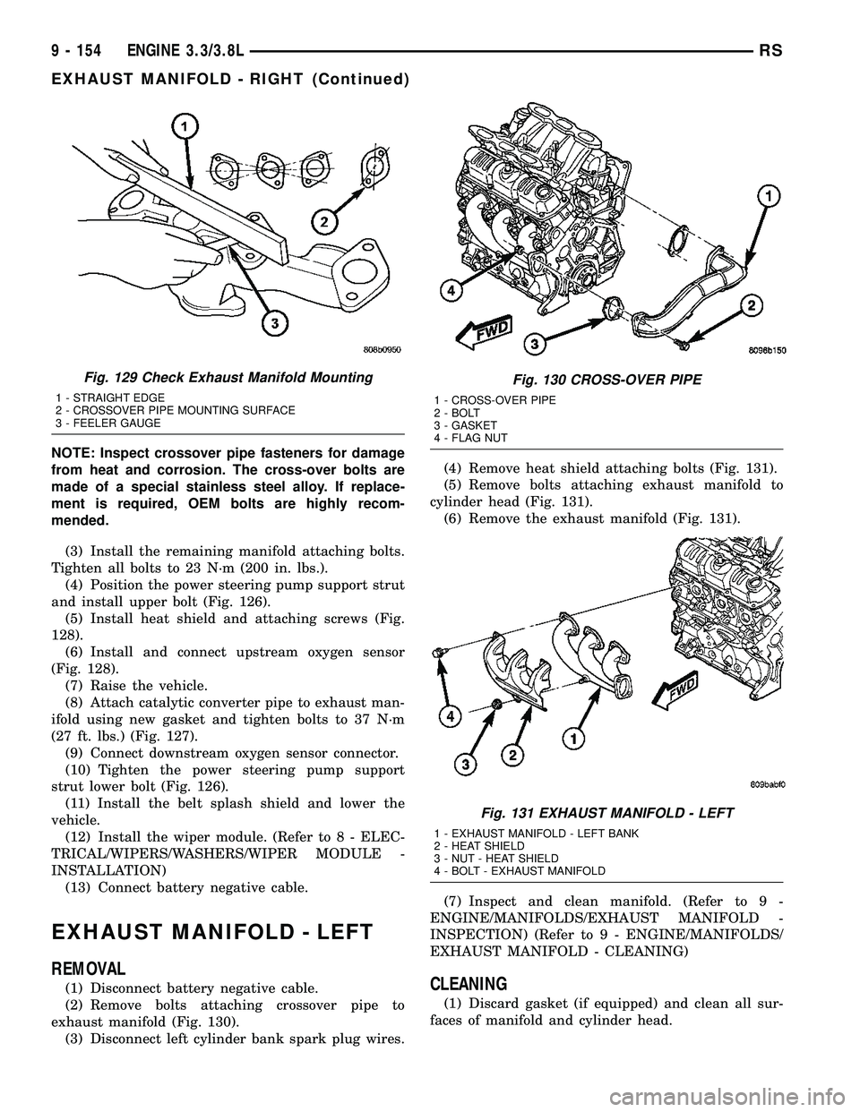
exhaust manifold (Fig. 130).
(3) Disconnect left cylinder bank spark plug wires.(4) Remove heat shield attaching bolts (Fig. 131).
(5) Remove bolts attaching exhaust manifold to
cylinder head (Fig. 131).
(6) Remove the exhaust manifold (Fig. 131).
(7) Inspect and clean manifold. (Refer to 9 -
ENGINE/MANIFOLDS/EXHAUST MANIFOLD -
INSPECTION) (Refer to 9 - ENGINE/MANIFOLDS/
EXHAUST MANIFOLD - CLEANING)CLEANING
(1) Discard gasket (if equipped) and clean all sur-
faces of manifold and cylinder head.
Fig. 129 Check Exhaust Manifold Mounting
1 - STRAIGHT EDGE
2 - CROSSOVER PIPE MOUNTING SURFACE
3 - FEELER GAUGE
Fig. 130 CROSS-OVER PIPE
1 - CROSS-OVER PIPE
2 - BOLT
3 - GASKET
4 - FLAG NUT
Fig. 131 EXHAUST MANIFOLD - LEFT
1 - EXHAUST MANIFOLD - LEFT BANK
2 - HEAT SHIELD
3 - NUT - HEAT SHIELD
4 - BOLT - EXHAUST MANIFOLD
9 - 154 ENGINE 3.3/3.8LRS
EXHAUST MANIFOLD - RIGHT (Continued)
Page 1447 of 2339
(12) Remove the fasteners, then the accessory
drive splash shield.
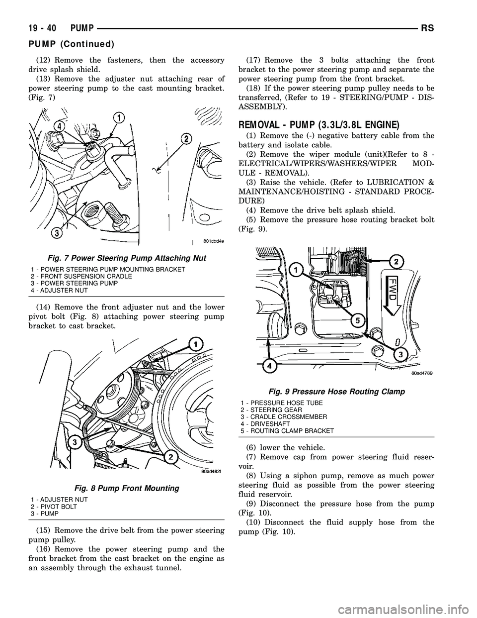
(13) Remove the adjuster nut attaching rear of
power steering pump to the cast mounting bracket.
(Fig. 7)
(14) Remove the front adjuster nut and the lower
pivot bolt (Fig. 8) attaching power steering pump
bracket to cast bracket.
(15) Remove the drive belt from the power steering
pump pulley.
(16) Remove the power steering pump and the
front bracket from the cast bracket on the engine as
an assembly through the exhaust tunnel.(17) Remove the 3 bolts attaching the front
bracket to the power steering pump and separate the
power steering pump from the front bracket.
(18) If the power steering pump pulley needs to be
transferred, (Refer to 19 - STEERING/PUMP - DIS-
ASSEMBLY).
REMOVAL - PUMP (3.3L/3.8L ENGINE)
(1) Remove the (-) negative battery cable from the
battery and isolate cable.
(2) Remove the wiper module (unit)(Refer to 8 -
ELECTRICAL/WIPERS/WASHERS/WIPER MOD-
ULE - REMOVAL).
(3) Raise the vehicle. (Refer to LUBRICATION &
MAINTENANCE/HOISTING - STANDARD PROCE-
DURE)
(4) Remove the drive belt splash shield.
(5) Remove the pressure hose routing bracket bolt
(Fig. 9).
(6) lower the vehicle.
(7) Remove cap from power steering fluid reser-
voir.
(8) Using a siphon pump, remove as much power
steering fluid as possible from the power steering
fluid reservoir.
(9) Disconnect the pressure hose from the pump
(Fig. 10).
(10) Disconnect the fluid supply hose from the
pump (Fig. 10).
Fig. 7 Power Steering Pump Attaching Nut
1 - POWER STEERING PUMP MOUNTING BRACKET
2 - FRONT SUSPENSION CRADLE
3 - POWER STEERING PUMP
4 - ADJUSTER NUT
Fig. 8 Pump Front Mounting
1 - ADJUSTER NUT
2 - PIVOT BOLT
3 - PUMP
Fig. 9 Pressure Hose Routing Clamp
1 - PRESSURE HOSE TUBE
2 - STEERING GEAR
3 - CRADLE CROSSMEMBER
4 - DRIVESHAFT
5 - ROUTING CLAMP BRACKET
19 - 40 PUMPRS
PUMP (Continued)
Page 1450 of 2339
INSTALLATION
INSTALLATION - PUMP (2.4L ENGINE)
(1) Install power steering pump back in vehicle
using the reverse order of its removal through the
exhaust tunnel of the vehicle.
(2) Install the power steering pump on its cast
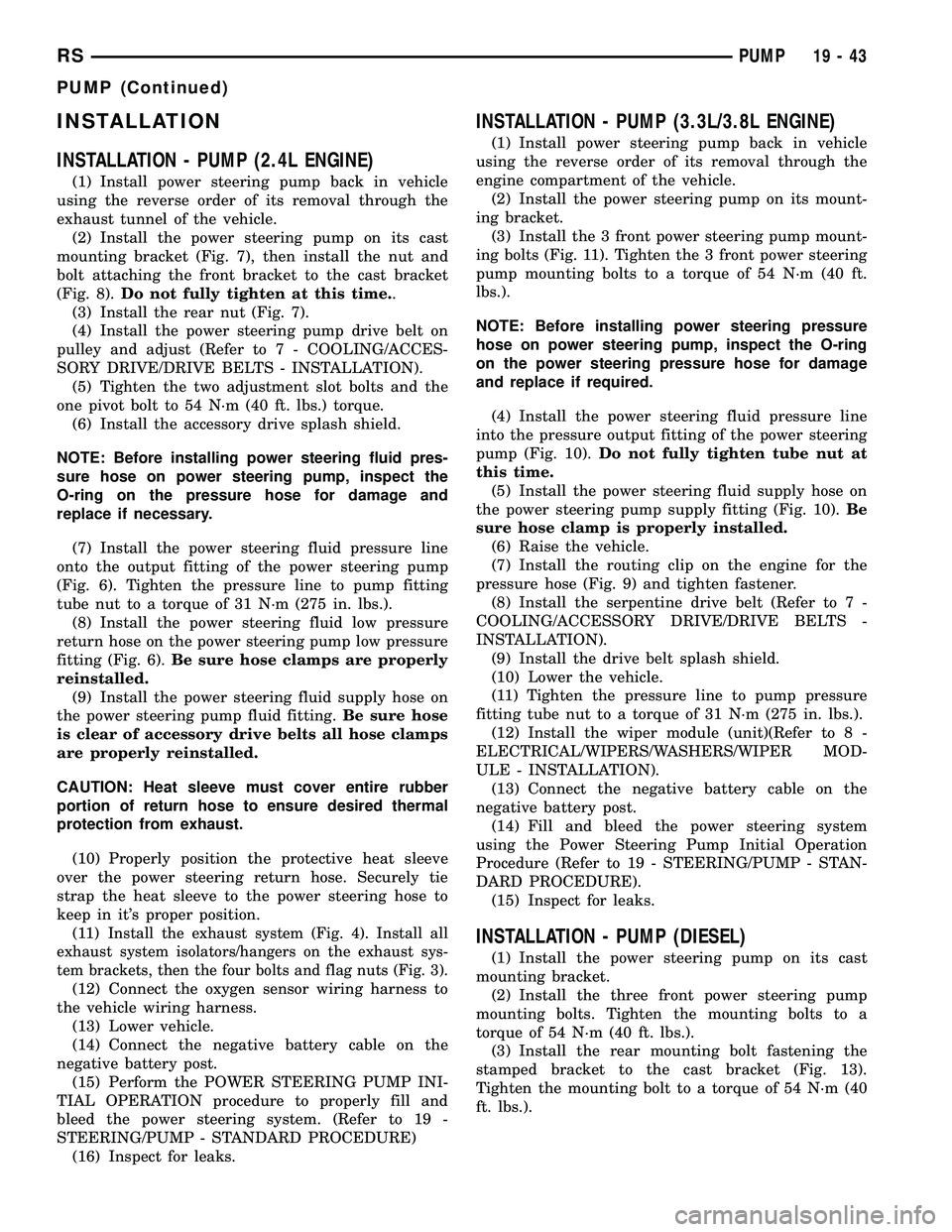
mounting bracket (Fig. 7), then install the nut and
bolt attaching the front bracket to the cast bracket
(Fig. 8).Do not fully tighten at this time..
(3) Install the rear nut (Fig. 7).
(4) Install the power steering pump drive belt on
pulley and adjust (Refer to 7 - COOLING/ACCES-
SORY DRIVE/DRIVE BELTS - INSTALLATION).
(5) Tighten the two adjustment slot bolts and the
one pivot bolt to 54 N´m (40 ft. lbs.) torque.
(6) Install the accessory drive splash shield.
NOTE: Before installing power steering fluid pres-
sure hose on power steering pump, inspect the
O-ring on the pressure hose for damage and
replace if necessary.
(7) Install the power steering fluid pressure line
onto the output fitting of the power steering pump
(Fig. 6). Tighten the pressure line to pump fitting
tube nut to a torque of 31 N´m (275 in. lbs.).
(8) Install the power steering fluid low pressure
return hose on the power steering pump low pressure
fitting (Fig. 6).Be sure hose clamps are properly
reinstalled.
(9) Install the power steering fluid supply hose on
the power steering pump fluid fitting.Be sure hose
is clear of accessory drive belts all hose clamps
are properly reinstalled.
CAUTION: Heat sleeve must cover entire rubber
portion of return hose to ensure desired thermal
protection from exhaust.
(10) Properly position the protective heat sleeve
over the power steering return hose. Securely tie
strap the heat sleeve to the power steering hose to
keep in it's proper position.
(11)
Install the exhaust system (Fig. 4). Install all
exhaust system isolators/hangers on the exhaust sys-
tem brackets, then the four bolts and flag nuts (Fig. 3).
(12) Connect the oxygen sensor wiring harness to
the vehicle wiring harness.
(13) Lower vehicle.
(14) Connect the negative battery cable on the
negative battery post.
(15) Perform the POWER STEERING PUMP INI-
TIAL OPERATION procedure to properly fill and
bleed the power steering system. (Refer to 19 -
STEERING/PUMP - STANDARD PROCEDURE)
(16) Inspect for leaks.
INSTALLATION - PUMP (3.3L/3.8L ENGINE)
(1) Install power steering pump back in vehicle
using the reverse order of its removal through the
engine compartment of the vehicle.
(2) Install the power steering pump on its mount-
ing bracket.
(3) Install the 3 front power steering pump mount-
ing bolts (Fig. 11). Tighten the 3 front power steering
pump mounting bolts to a torque of 54 N´m (40 ft.
lbs.).
NOTE: Before installing power steering pressure
hose on power steering pump, inspect the O-ring
on the power steering pressure hose for damage
and replace if required.
(4) Install the power steering fluid pressure line
into the pressure output fitting of the power steering
pump (Fig. 10).Do not fully tighten tube nut at
this time.
(5) Install the power steering fluid supply hose on
the power steering pump supply fitting (Fig. 10).Be
sure hose clamp is properly installed.
(6) Raise the vehicle.
(7) Install the routing clip on the engine for the
pressure hose (Fig. 9) and tighten fastener.
(8) Install the serpentine drive belt (Refer to 7 -
COOLING/ACCESSORY DRIVE/DRIVE BELTS -
INSTALLATION).
(9) Install the drive belt splash shield.
(10) Lower the vehicle.
(11) Tighten the pressure line to pump pressure
fitting tube nut to a torque of 31 N´m (275 in. lbs.).
(12) Install the wiper module (unit)(Refer to 8 -
ELECTRICAL/WIPERS/WASHERS/WIPER MOD-
ULE - INSTALLATION).
(13) Connect the negative battery cable on the
negative battery post.
(14) Fill and bleed the power steering system
using the Power Steering Pump Initial Operation
Procedure (Refer to 19 - STEERING/PUMP - STAN-
DARD PROCEDURE).
(15) Inspect for leaks.
INSTALLATION - PUMP (DIESEL)
(1) Install the power steering pump on its cast
mounting bracket.
(2) Install the three front power steering pump
mounting bolts. Tighten the mounting bolts to a
torque of 54 N´m (40 ft. lbs.).
(3) Install the rear mounting bolt fastening the
stamped bracket to the cast bracket (Fig. 13).
Tighten the mounting bolt to a torque of 54 N´m (40
ft. lbs.).
RSPUMP19-43
PUMP (Continued)
Page 1829 of 2339
COWL GRILLE
REMOVAL
(1) Remove wiper arms. (Refer to 8 - ELECTRI-
CAL/WIPERS/WASHERS/WIPER ARMS -
REMOVAL)
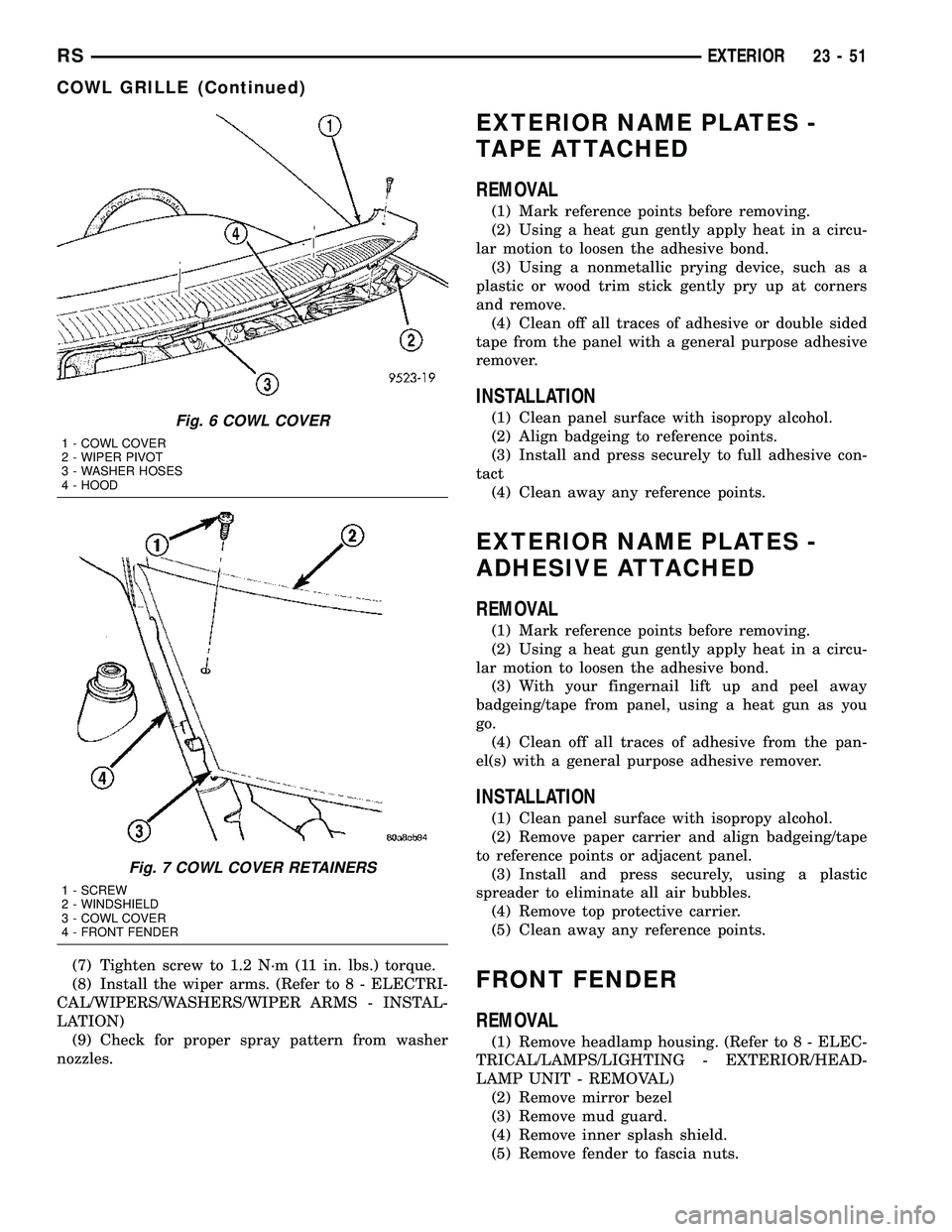
(2) Remove four (4) screws securing cowl cover to
wiper module (Fig. 6).
(3) Disengage quarter turn fasteners at outboard
ends of cowl grill from body.
(4) Release hood latch and open hood.
CAUTION: To prevent hood scratching of cowl grille
before removal, cover outboard exterior ends of
cowl grille with masking tape or equivalent method.
NOTE: Do not over bend cowl grille during removal.
Bend cowl grille just enough to clear top of wiper
pivot shaft and bottom rear corner of hood.
(5) Remove cowl grill by raising above driver side
wiper pivot shaft and swinging away towards engine
compartment. The cowl grille will need to be bent onoutboard end to clear simultaneously top of wiper
pivot shaft and bottom corner of hood.
(6) Close hood. Do not latch. Remove outboard
screws. (Fig. 7).
(7) Disconnect washer hose in line connector.
(8) Disconnect washer hose and grommet from
hole in wiper module and pull out.
(9) Remove cowl grille by raising over opposite
wiper pivot shaft and removing away from vehicle.
(10) Remove cowl cover from vehicle.
INSTALLATION
(1) Reverse removal procedure.
(2) When installing cowl cover over wiper module,
make sure fore aft locator on the underside of cowl
grill seat into the locator grooves on top of wiper
module.
(3) Start all cowl grille mounting screws by hand
before torquing to specifications.
(4) Assure washer hose is properly routed and not
pinched.
(5) Center cowl grille to body and windshield.
(6) Assure ªarrowº indicator head of quarter turn
fasteners is pointing toward windshield.
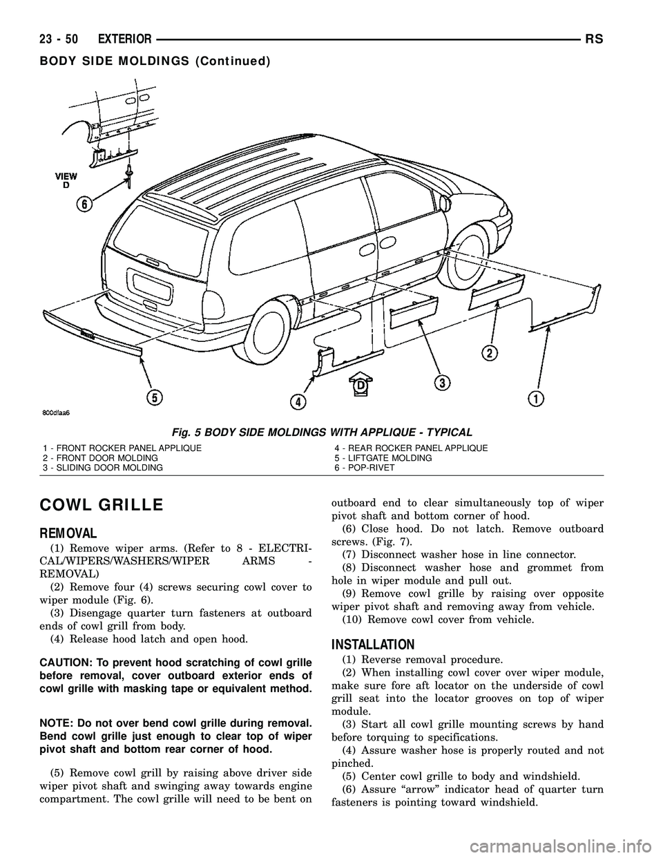
Fig. 5 BODY SIDE MOLDINGS WITH APPLIQUE - TYPICAL
1 - FRONT ROCKER PANEL APPLIQUE
2 - FRONT DOOR MOLDING
3 - SLIDING DOOR MOLDING4 - REAR ROCKER PANEL APPLIQUE
5 - LIFTGATE MOLDING
6 - POP-RIVET
23 - 50 EXTERIORRS
BODY SIDE MOLDINGS (Continued)
Page 1830 of 2339
(7) Tighten screw to 1.2 N´m (11 in. lbs.) torque.
(8) Install the wiper arms. (Refer to 8 - ELECTRI-
CAL/WIPERS/WASHERS/WIPER ARMS - INSTAL-
LATION)
(9) Check for proper spray pattern from washer
nozzles.
EXTERIOR NAME PLATES -
TAPE ATTACHED
REMOVAL
(1) Mark reference points before removing.
(2) Using a heat gun gently apply heat in a circu-
lar motion to loosen the adhesive bond.
(3) Using a nonmetallic prying device, such as a
plastic or wood trim stick gently pry up at corners
and remove.
(4) Clean off all traces of adhesive or double sided
tape from the panel with a general purpose adhesive
remover.
INSTALLATION
(1) Clean panel surface with isopropy alcohol.
(2) Align badgeing to reference points.
(3) Install and press securely to full adhesive con-
tact
(4) Clean away any reference points.
EXTERIOR NAME PLATES -
ADHESIVE ATTACHED
REMOVAL
(1) Mark reference points before removing.
(2) Using a heat gun gently apply heat in a circu-
lar motion to loosen the adhesive bond.
(3) With your fingernail lift up and peel away
badgeing/tape from panel, using a heat gun as you
go.
(4) Clean off all traces of adhesive from the pan-
el(s) with a general purpose adhesive remover.
INSTALLATION
(1) Clean panel surface with isopropy alcohol.
(2) Remove paper carrier and align badgeing/tape
to reference points or adjacent panel.
(3) Install and press securely, using a plastic
spreader to eliminate all air bubbles.
(4) Remove top protective carrier.
(5) Clean away any reference points.
FRONT FENDER
REMOVAL
(1) Remove headlamp housing. (Refer to 8 - ELEC-
TRICAL/LAMPS/LIGHTING - EXTERIOR/HEAD-
LAMP UNIT - REMOVAL)
(2) Remove mirror bezel
(3) Remove mud guard.
(4) Remove inner splash shield.
(5) Remove fender to fascia nuts.
Fig. 6 COWL COVER
1 - COWL COVER
2 - WIPER PIVOT
3 - WASHER HOSES
4 - HOOD
Fig. 7 COWL COVER RETAINERS
1 - SCREW
2 - WINDSHIELD
3 - COWL COVER
4 - FRONT FENDER
RSEXTERIOR23-51
COWL GRILLE (Continued)
Page 1841 of 2339
HOOD
TABLE OF CONTENTS
page page
HINGE
REMOVAL.............................62
INSTALLATION.........................62
HOOD
REMOVAL.............................62
INSTALLATION.........................63
LATCH
REMOVAL.............................63INSTALLATION.........................63
LATCH RELEASE CABLE
REMOVAL.............................63
INSTALLATION.........................64
LATCH STRIKER
REMOVAL.............................64
INSTALLATION.........................64
HINGE
REMOVAL
(1) Remove Front Wiper Unit (Refer to 8 - ELEC-
TRICAL/WIPERS/WASHERS/WIPER MODULE -
REMOVAL) for procedure.
(2) Raise hood.
(3) Mark all bolt and hinge attachment locations
with a grease pencil or other suitable device to pro-
vide reference marks for installation.
(4) Remove pivot bolt from the body half of hood
hinge and use suitable device to support the hood.
(5) Remove bolts attaching body half of hood hinge
to front fender flange and remove hinge from vehicle
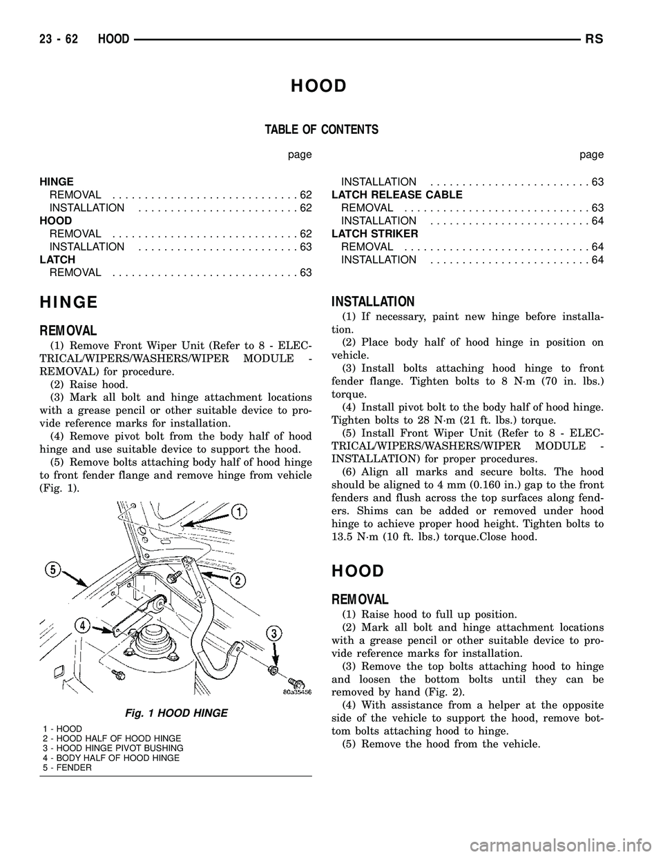
(Fig. 1).
INSTALLATION
(1) If necessary, paint new hinge before installa-
tion.
(2) Place body half of hood hinge in position on
vehicle.
(3) Install bolts attaching hood hinge to front
fender flange. Tighten bolts to 8 N´m (70 in. lbs.)
torque.
(4) Install pivot bolt to the body half of hood hinge.
Tighten bolts to 28 N´m (21 ft. lbs.) torque.
(5) Install Front Wiper Unit (Refer to 8 - ELEC-
TRICAL/WIPERS/WASHERS/WIPER MODULE -
INSTALLATION) for proper procedures.
(6) Align all marks and secure bolts. The hood
should be aligned to 4 mm (0.160 in.) gap to the front
fenders and flush across the top surfaces along fend-
ers. Shims can be added or removed under hood
hinge to achieve proper hood height. Tighten bolts to
13.5 N´m (10 ft. lbs.) torque.Close hood.
HOOD
REMOVAL
(1) Raise hood to full up position.
(2) Mark all bolt and hinge attachment locations
with a grease pencil or other suitable device to pro-
vide reference marks for installation.
(3) Remove the top bolts attaching hood to hinge
and loosen the bottom bolts until they can be
removed by hand (Fig. 2).
(4) With assistance from a helper at the opposite
side of the vehicle to support the hood, remove bot-
tom bolts attaching hood to hinge.
(5) Remove the hood from the vehicle.
Fig. 1 HOOD HINGE
1 - HOOD
2 - HOOD HALF OF HOOD HINGE
3 - HOOD HINGE PIVOT BUSHING
4 - BODY HALF OF HOOD HINGE
5 - FENDER
23 - 62 HOODRS