2005 CHRYSLER VOYAGER Door actuator
[x] Cancel search: Door actuatorPage 1117 of 2339
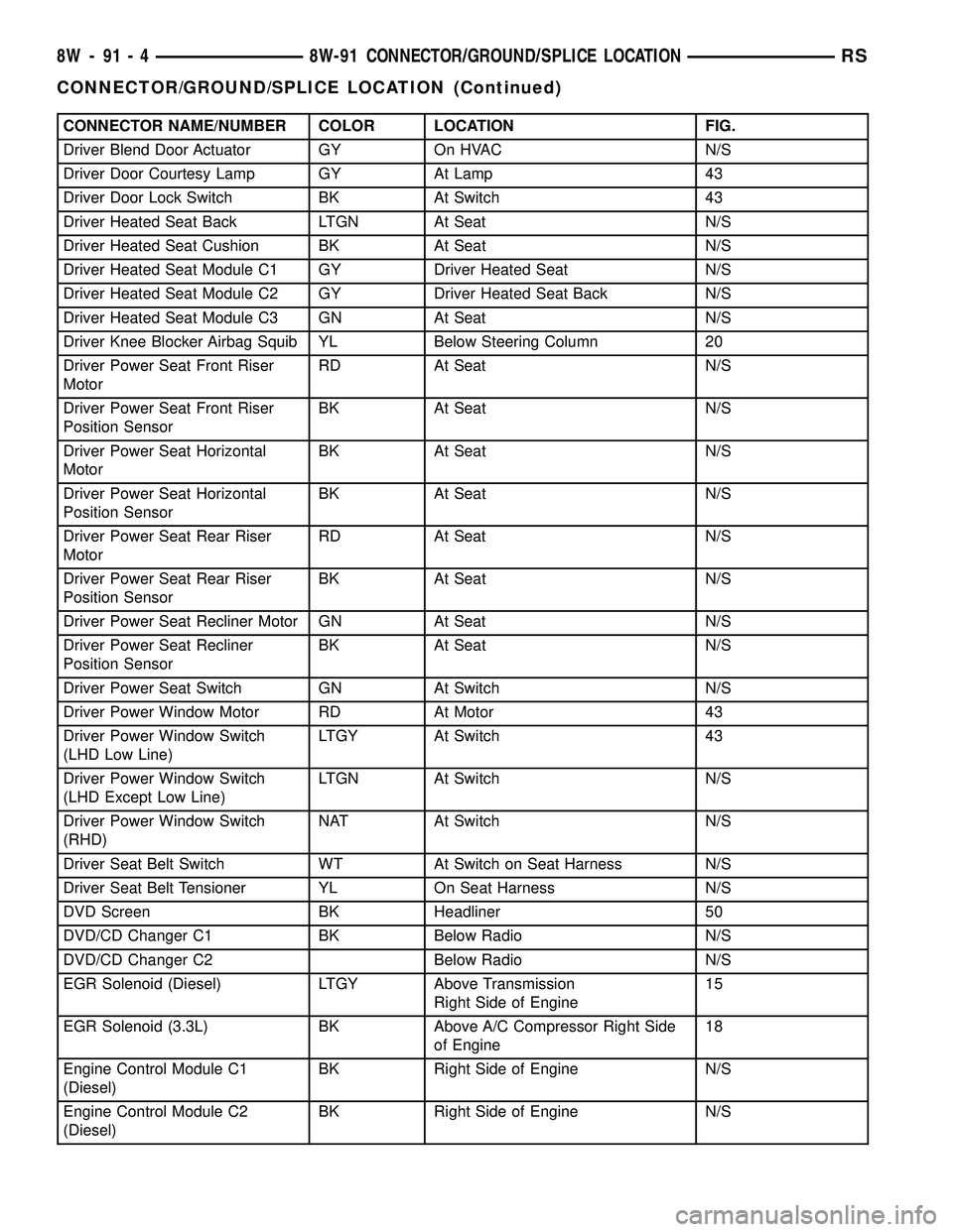
CONNECTOR NAME/NUMBER COLOR LOCATION FIG.
Driver Blend Door Actuator GY On HVAC N/S
Driver Door Courtesy Lamp GY At Lamp 43
Driver Door Lock Switch BK At Switch 43
Driver Heated Seat Back LTGN At Seat N/S
Driver Heated Seat Cushion BK At Seat N/S
Driver Heated Seat Module C1 GY Driver Heated Seat N/S
Driver Heated Seat Module C2 GY Driver Heated Seat Back N/S
Driver Heated Seat Module C3 GN At Seat N/S
Driver Knee Blocker Airbag Squib YL Below Steering Column 20
Driver Power Seat Front Riser
MotorRD At Seat N/S
Driver Power Seat Front Riser
Position SensorBK At Seat N/S
Driver Power Seat Horizontal
MotorBK At Seat N/S
Driver Power Seat Horizontal
Position SensorBK At Seat N/S
Driver Power Seat Rear Riser
MotorRD At Seat N/S
Driver Power Seat Rear Riser
Position SensorBK At Seat N/S
Driver Power Seat Recliner Motor GN At Seat N/S
Driver Power Seat Recliner
Position SensorBK At Seat N/S
Driver Power Seat Switch GN At Switch N/S
Driver Power Window Motor RD At Motor 43
Driver Power Window Switch
(LHD Low Line)LTGY At Switch 43
Driver Power Window Switch
(LHD Except Low Line)LTGN At Switch N/S
Driver Power Window Switch
(RHD)NAT At Switch N/S
Driver Seat Belt Switch WT At Switch on Seat Harness N/S
Driver Seat Belt Tensioner YL On Seat Harness N/S
DVD Screen BK Headliner 50
DVD/CD Changer C1 BK Below Radio N/S
DVD/CD Changer C2 Below Radio N/S
EGR Solenoid (Diesel) LTGY Above Transmission
Right Side of Engine15
EGR Solenoid (3.3L) BK Above A/C Compressor Right Side
of Engine18
Engine Control Module C1
(Diesel)BK Right Side of Engine N/S
Engine Control Module C2
(Diesel)BK Right Side of Engine N/S
8W - 91 - 4 8W-91 CONNECTOR/GROUND/SPLICE LOCATIONRS
CONNECTOR/GROUND/SPLICE LOCATION (Continued)
Page 1121 of 2339
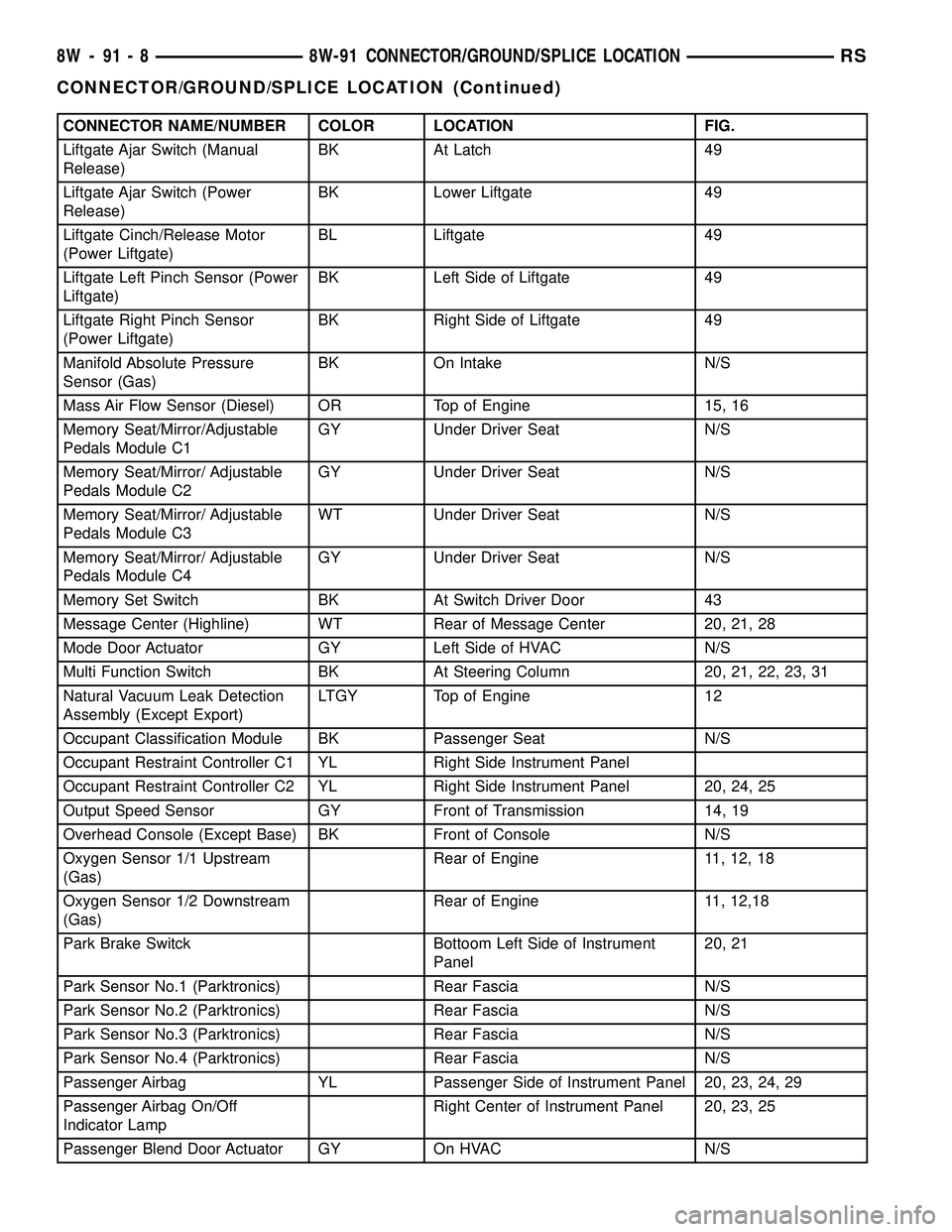
CONNECTOR NAME/NUMBER COLOR LOCATION FIG.
Liftgate Ajar Switch (Manual
Release)BK At Latch 49
Liftgate Ajar Switch (Power
Release)BK Lower Liftgate 49
Liftgate Cinch/Release Motor
(Power Liftgate)BL Liftgate 49
Liftgate Left Pinch Sensor (Power
Liftgate)BK Left Side of Liftgate 49
Liftgate Right Pinch Sensor
(Power Liftgate)BK Right Side of Liftgate 49
Manifold Absolute Pressure
Sensor (Gas)BK On Intake N/S
Mass Air Flow Sensor (Diesel) OR Top of Engine 15, 16
Memory Seat/Mirror/Adjustable
Pedals Module C1GY Under Driver Seat N/S
Memory Seat/Mirror/ Adjustable
Pedals Module C2GY Under Driver Seat N/S
Memory Seat/Mirror/ Adjustable
Pedals Module C3WT Under Driver Seat N/S
Memory Seat/Mirror/ Adjustable
Pedals Module C4GY Under Driver Seat N/S
Memory Set Switch BK At Switch Driver Door 43
Message Center (Highline) WT Rear of Message Center 20, 21, 28
Mode Door Actuator GY Left Side of HVAC N/S
Multi Function Switch BK At Steering Column 20, 21, 22, 23, 31
Natural Vacuum Leak Detection
Assembly (Except Export)LTGY Top of Engine 12
Occupant Classification Module BK Passenger Seat N/S
Occupant Restraint Controller C1 YL Right Side Instrument Panel
Occupant Restraint Controller C2 YL Right Side Instrument Panel 20, 24, 25
Output Speed Sensor GY Front of Transmission 14, 19
Overhead Console (Except Base) BK Front of Console N/S
Oxygen Sensor 1/1 Upstream
(Gas)Rear of Engine 11, 12, 18
Oxygen Sensor 1/2 Downstream
(Gas)Rear of Engine 11, 12,18
Park Brake Switck Bottoom Left Side of Instrument
Panel20, 21
Park Sensor No.1 (Parktronics) Rear Fascia N/S
Park Sensor No.2 (Parktronics) Rear Fascia N/S
Park Sensor No.3 (Parktronics) Rear Fascia N/S
Park Sensor No.4 (Parktronics) Rear Fascia N/S
Passenger Airbag YL Passenger Side of Instrument Panel 20, 23, 24, 29
Passenger Airbag On/Off
Indicator LampRight Center of Instrument Panel 20, 23, 25
Passenger Blend Door Actuator GY On HVAC N/S
8W - 91 - 8 8W-91 CONNECTOR/GROUND/SPLICE LOCATIONRS
CONNECTOR/GROUND/SPLICE LOCATION (Continued)
Page 1123 of 2339
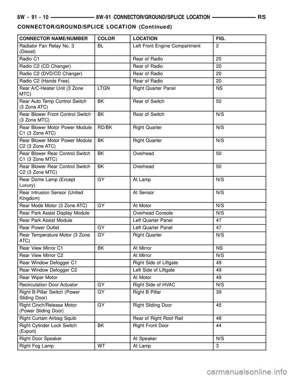
CONNECTOR NAME/NUMBER COLOR LOCATION FIG.
Radiator Fan Relay No. 3
(Diesel)BL Left Front Engine Compartment 2
Radio C1 Rear of Radio 20
Radio C2 (CD Changer) Rear of Radio 20
Radio C2 (DVD/CD Changer) Rear of Radio 20
Radio C2 (Hands Free) Rear of Radio 20
Rear A/C-Heater Unit (3 Zone
MTC)LTGN Right Quarter Panel NS
Rear Auto Temp Control Switch
(3 Zone ATC)BK Rear of Switch 50
Rear Blower Front Control Switch
(3 Zone MTC)BK Rear of Switch N/S
Rear Blower Motor Power Module
C1 (3 Zone ATC)RD/BK Right Quarter N/S
Rear Blower Motor Power Module
C2 (3 Zone ATC)BK Right Quarter N/S
Rear Blower Rear Control Switch
C1 (3 Zone MTC)BK Overhead 50
Rear Blower Rear Control Switch
C2 (3 Zone MTC)BK Overhead 50
Rear Dome Lamp (Except
Luxury)GY At Lamp N/S
Rear Intrusion Sensor (United
Kingdom)At Sensor N/S
Rear Mode Motor (3 Zone ATC) GY At Motor N/S
Rear Park Assist Display Module Overhead Console N/S
Rear Park Assist Module Left Quarter Panel 47
Rear Power Outlet GY Left Quarter Panel 47
Rear Temperature Motor (3 Zone
ATC)GY Right Quarter N/S
Rear View Mirror C1 BK At Mirror NS
Rear View Mirror C2 At Mirror N/S
Rear Window Defogger C1 Right Side of Liftgate 49
Rear Window Defogger C2 Left Side of Liftgate 49
Rear Wiper Motor At Motor 49
Recirculation Door Actuator GY Right Side of HVAC N/S
Right B-Pillar Switch (Power
Sliding Door)GY Right B Pillar 39
Right Cinch/Release Motor
(Power Sliding Door)GY Right Sliding Door 45
Right Curtain Airbag Squib Rear of Right Roof Rail 48
Right Cylinder Lock Switch
(Export)BK Right Front Door 44
Right Door Speaker At Speaker N/S
Right Fog Lamp WT At Lamp 3
8W - 91 - 10 8W-91 CONNECTOR/GROUND/SPLICE LOCATIONRS
CONNECTOR/GROUND/SPLICE LOCATION (Continued)
Page 1803 of 2339

DOORS - SLIDING
TABLE OF CONTENTS
page page
CENTER HINGE
REMOVAL.............................24
INSTALLATION.........................24
SLIDING DOOR STOP BUMPER BEZEL
REMOVAL.............................25
INSTALLATION.........................25
STOP BUMPER
REMOVAL.............................25
INSTALLATION.........................25
HOLD OPEN LATCH
REMOVAL.............................25
INSTALLATION.........................25
HOLD OPEN LATCH STRIKER
REMOVAL.............................26
INSTALLATION.........................26
LATCH / LOCK ASSEMBLY
REMOVAL.............................26
INSTALLATION.........................27
INSIDE HANDLE ACTUATOR
REMOVAL.............................27
INSTALLATION.........................27
CENTER STRIKER
REMOVAL.............................28
INSTALLATION.........................28
LOWER HINGE
REMOVAL.............................28
INSTALLATION.........................28
REAR LATCH STRIKER
REMOVAL.............................29
INSTALLATION.........................29
SLIDING DOOR
REMOVAL.............................29
INSTALLATION.........................29ADJUSTMENTS
SLIDING DOOR ADJUSTMENTS..........30
STABILIZER
REMOVAL.............................33
INSTALLATION.........................33
STABILIZER SOCKET
REMOVAL.............................33
INSTALLATION.........................33
TRIM PANEL
REMOVAL.............................34
INSTALLATION.........................34
INSIDE LATCH HANDLE
REMOVAL.............................34
INSTALLATION.........................34
BELLCRANK
REMOVAL.............................35
INSTALLATION.........................35
OUTSIDE HANDLE
REMOVAL.............................35
INSTALLATION.........................36
UPPER HINGE
REMOVAL.............................36
INSTALLATION.........................36
OUTSIDE HANDLE CABLE
REMOVAL.............................37
INSTALLATION.........................37
INSIDE HANDLE CABLE
REMOVAL.............................37
INSTALLATION.........................38
HOLD OPEN LATCH CABLE
REMOVAL.............................38
INSTALLATION.........................38
CENTER HINGE
REMOVAL
NOTE: For power sliding door procedures refer to
POWER SLIDING DOOR SYSTEM in the ELECTRI-
CAL section.
(1) Open sliding door to the mid point of its travel.
(2) Support sliding door on a suitable lifting
device.
(3) Mark outline of center hinge of inner door
panel to aid installation.(4) Remove bolts attaching center hinge to sliding
door.
(5) Remove center hinge from sliding door.
(6) Roll center hinge to rear of roller channel.
(7) Remove center hinge from vehicle.
INSTALLATION
NOTE: For power sliding door procedures refer to
POWER SLIDING DOOR SYSTEM in the ELECTRI-
CAL section.
23 - 24 DOORS - SLIDINGRS
Page 1806 of 2339
INSTALLATION
NOTE: For power sliding door procedures refer to
POWER SLIDING DOOR SYSTEM in the ELECTRI-
CAL section.
(1) Position latch/lock locking lever in unlocked
position.
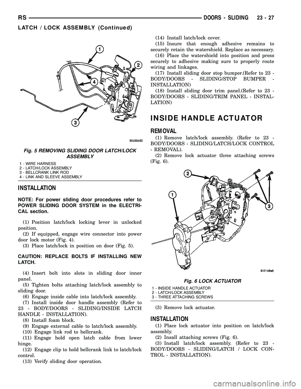
(2) If equipped, engage wire connector into power
door lock motor (Fig. 4).
(3) Place latch/lock in position on door (Fig. 5).
CAUTION: REPLACE BOLTS IF INSTALLING NEW
LATCH.
(4) Insert bolt into slots in sliding door inner
panel.
(5) Tighten bolts attaching latch/lock assembly to
sliding door.
(6) Engage inside cable into latch/lock assembly.
(7) Install inside door handle assembly (Refer to
23 - BODY/DOORS - SLIDING/INSIDE LATCH
HANDLE - INSTALLATION).
(8) Install foam block.
(9) Engage external cable to latch/lock assembly.
(10) Engage link rod to bellcrank.
(11) Engage hold open latch cable from lower
hinge.
(12) Engage clip to hold bellcrank link to latch/lock
control.
(13) Verify sliding door operation.(14) Install latch/lock cover.
(15) Insure that enough adhesive remains to
securely retain the watershield. Replace as necessary.
(16) Place the watershield into position and press
securely to adhesive making sure to properly route
wiring and linkages.
(17) Install sliding door stop bumper.(Refer to 23 -
BODY/DOORS - SLIDING/STOP BUMPER -
INSTALLATION)
(18) Install sliding door trim panel.(Refer to 23 -
BODY/DOORS - SLIDING/TRIM PANEL - INSTAL-
LATION)
INSIDE HANDLE ACTUATOR
REMOVAL
(1) Remove latch/lock assembly. (Refer to 23 -
BODY/DOORS - SLIDING/LATCH/LOCK CONTROL
- REMOVAL).
(2) Remove lock actuator three attaching screws
(Fig. 6).
(3) Remove lock actuator.
INSTALLATION
(1) Place lock actuator into position on latch/lock
assembly.
(2) Insall attaching screws (Fig. 6).
(3) Install latch/lock assembly. (Refer to 23 -
BODY/DOORS - SLIDING/LATCH / LOCK CON-
TROL - INSTALLATION).
Fig. 5 REMOVING SLIDING DOOR LATCH/LOCK
ASSEMBLY
1 - WIRE HARNESS
2 - LATCH/LOCK ASSEMBLY
3 - BELLCRANK LINK ROD
4 - LINK AND SLEEVE ASSEMBLY
Fig. 6 LOCK ACTUATOR
1 - INSIDE HANDLE ACTUATOR
2 - LATCH/LOCK ASSEMBLY
3 - THREE ATTACHING SCREWS
RSDOORS - SLIDING23-27
LATCH / LOCK ASSEMBLY (Continued)
Page 2152 of 2339
HEATING & AIR CONDITIONING
TABLE OF CONTENTS
page page
HEATING & AIR CONDITIONING
DESCRIPTION
ENGINE COOLING SYSTEM
REQUIREMENTS.......................1
HEATER AND AIR CONDITIONER..........1
MANUAL SINGLE ZONE.................2
MANUAL DUAL ZONE...................2
MANUAL THREE ZONE..................2
AUTOMATIC TEMPERATURE CONTROL....3
OPERATION
HEATER AND AIR CONDITIONER..........4
MANUAL SINGLE ZONE.................4
MANUAL DUAL ZONE...................5
MANUAL THREE ZONE..................5AUTOMATIC TEMPERATURE CONTROL....5
DIAGNOSIS AND TESTING
A/C COOL DOWN TEST.................6
A/C PERFORMANCE TEST...............7
HEATER PERFORMANCE TEST..........10
SPECIFICATIONS
A/C SYSTEM.........................11
CONTROLS - FRONT.....................13
CONTROLS - REAR......................33
DISTRIBUTION - FRONT...................42
DISTRIBUTION - REAR....................56
PLUMBING - FRONT.....................64
PLUMBING - REAR......................98
CABIN HEATER........................113
HEATING & AIR
CONDITIONING
DESCRIPTION
ENGINE COOLING SYSTEM REQUIREMENTS
To maintain the performance level of the heating,
ventilation and air conditioning (HVAC) system, the
engine cooling system must be properly maintained.
The use of a bug screen is not recommended. Any
obstructions in front of the radiator or condenser will
reduce the performance of the air conditioning and
engine cooling systems.
The engine cooling system includes the radiator,
thermostat, radiator hoses and the engine coolant
pump. Refer to Cooling for more information before
opening or attempting any service to the engine cool-
ing system.
HEATER AND AIR CONDITIONER
A manually controlled single zone type heating-air
conditioning system, manually controlled dual zone
type heating-air conditioning system, manually con-
trolled three zone type heating-air conditioning sys-
tem or an automatic controlled three zone type
heating-air conditioning system is available on this
model.
All vehicles are equipped with a common heater,
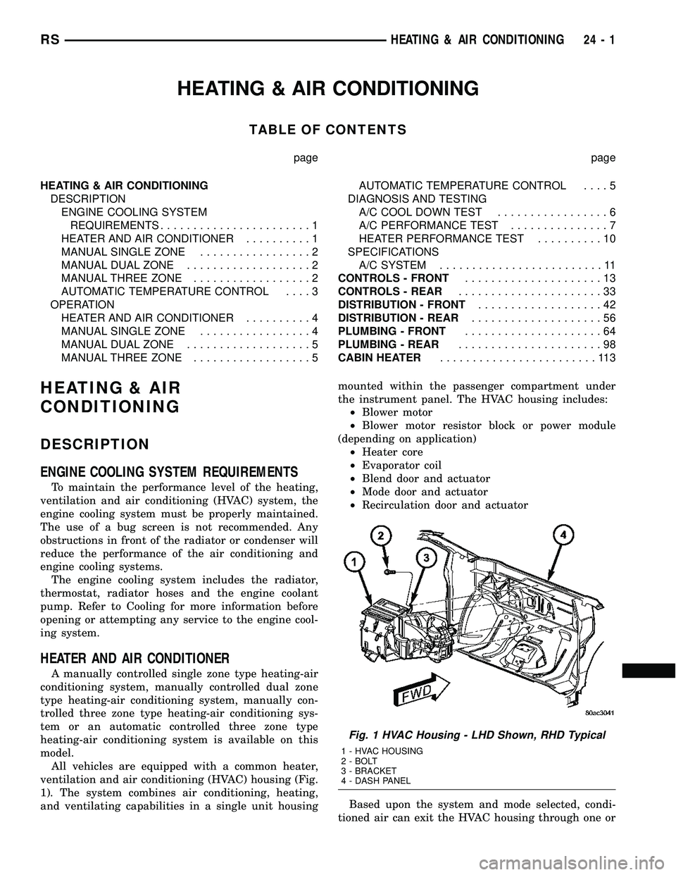
ventilation and air conditioning (HVAC) housing (Fig.
1). The system combines air conditioning, heating,
and ventilating capabilities in a single unit housingmounted within the passenger compartment under
the instrument panel. The HVAC housing includes:
²Blower motor
²Blower motor resistor block or power module
(depending on application)
²Heater core
²Evaporator coil
²Blend door and actuator
²Mode door and actuator
²Recirculation door and actuator
Based upon the system and mode selected, condi-
tioned air can exit the HVAC housing through one or
Fig. 1 HVAC Housing - LHD Shown, RHD Typical
1 - HVAC HOUSING
2 - BOLT
3 - BRACKET
4 - DASH PANEL
RSHEATING & AIR CONDITIONING24-1
Page 2160 of 2339
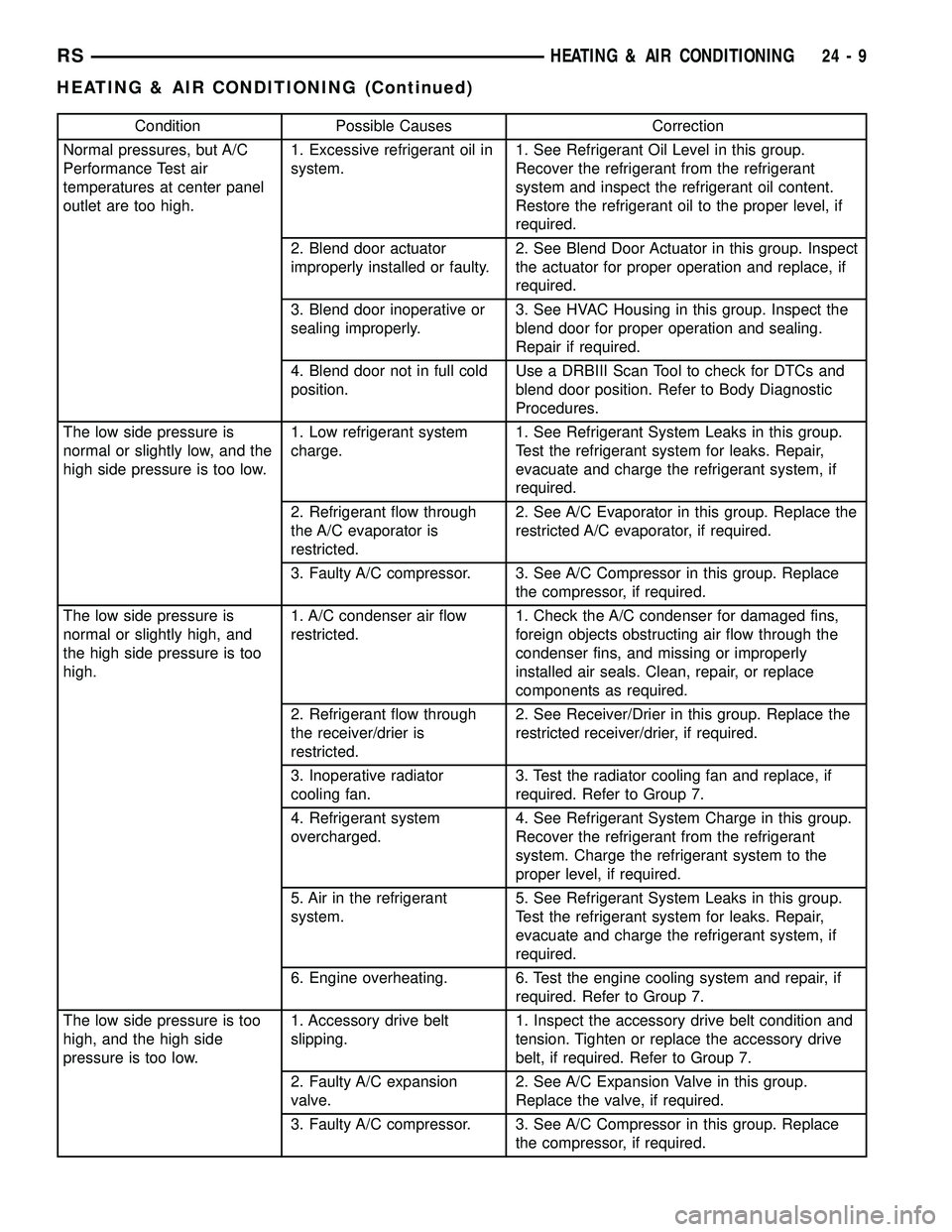
Condition Possible Causes Correction
Normal pressures, but A/C
Performance Test air
temperatures at center panel
outlet are too high.1. Excessive refrigerant oil in
system.1. See Refrigerant Oil Level in this group.
Recover the refrigerant from the refrigerant
system and inspect the refrigerant oil content.
Restore the refrigerant oil to the proper level, if
required.
2. Blend door actuator
improperly installed or faulty.2. See Blend Door Actuator in this group. Inspect
the actuator for proper operation and replace, if
required.
3. Blend door inoperative or
sealing improperly.3. See HVAC Housing in this group. Inspect the
blend door for proper operation and sealing.
Repair if required.
4. Blend door not in full cold
position.Use a DRBIII Scan Tool to check for DTCs and
blend door position. Refer to Body Diagnostic
Procedures.
The low side pressure is
normal or slightly low, and the
high side pressure is too low.1. Low refrigerant system
charge.1. See Refrigerant System Leaks in this group.
Test the refrigerant system for leaks. Repair,
evacuate and charge the refrigerant system, if
required.
2. Refrigerant flow through
the A/C evaporator is
restricted.2. See A/C Evaporator in this group. Replace the
restricted A/C evaporator, if required.
3. Faulty A/C compressor. 3. See A/C Compressor in this group. Replace
the compressor, if required.
The low side pressure is
normal or slightly high, and
the high side pressure is too
high.1. A/C condenser air flow
restricted.1. Check the A/C condenser for damaged fins,
foreign objects obstructing air flow through the
condenser fins, and missing or improperly
installed air seals. Clean, repair, or replace
components as required.
2. Refrigerant flow through
the receiver/drier is
restricted.2. See Receiver/Drier in this group. Replace the
restricted receiver/drier, if required.
3. Inoperative radiator
cooling fan.3. Test the radiator cooling fan and replace, if
required. Refer to Group 7.
4. Refrigerant system
overcharged.4. See Refrigerant System Charge in this group.
Recover the refrigerant from the refrigerant
system. Charge the refrigerant system to the
proper level, if required.
5. Air in the refrigerant
system.5. See Refrigerant System Leaks in this group.
Test the refrigerant system for leaks. Repair,
evacuate and charge the refrigerant system, if
required.
6. Engine overheating. 6. Test the engine cooling system and repair, if
required. Refer to Group 7.
The low side pressure is too
high, and the high side
pressure is too low.1. Accessory drive belt
slipping.1. Inspect the accessory drive belt condition and
tension. Tighten or replace the accessory drive
belt, if required. Refer to Group 7.
2. Faulty A/C expansion
valve.2. See A/C Expansion Valve in this group.
Replace the valve, if required.
3. Faulty A/C compressor. 3. See A/C Compressor in this group. Replace
the compressor, if required.
RSHEATING & AIR CONDITIONING24-9
HEATING & AIR CONDITIONING (Continued)
Page 2162 of 2339
TEMPERATURE CONTROL
If the heater outlet air temperature cannot be
adjusted with the temperature control knob on the
A/C-heater control panel, the following could require
service:
²Blend door binding.
²Faulty blend door actuator.
²Faulty A/C-heater control.
²Faulty related wiring harness or connectors.²Improper engine coolant temperature.
SPECIFICATIONS
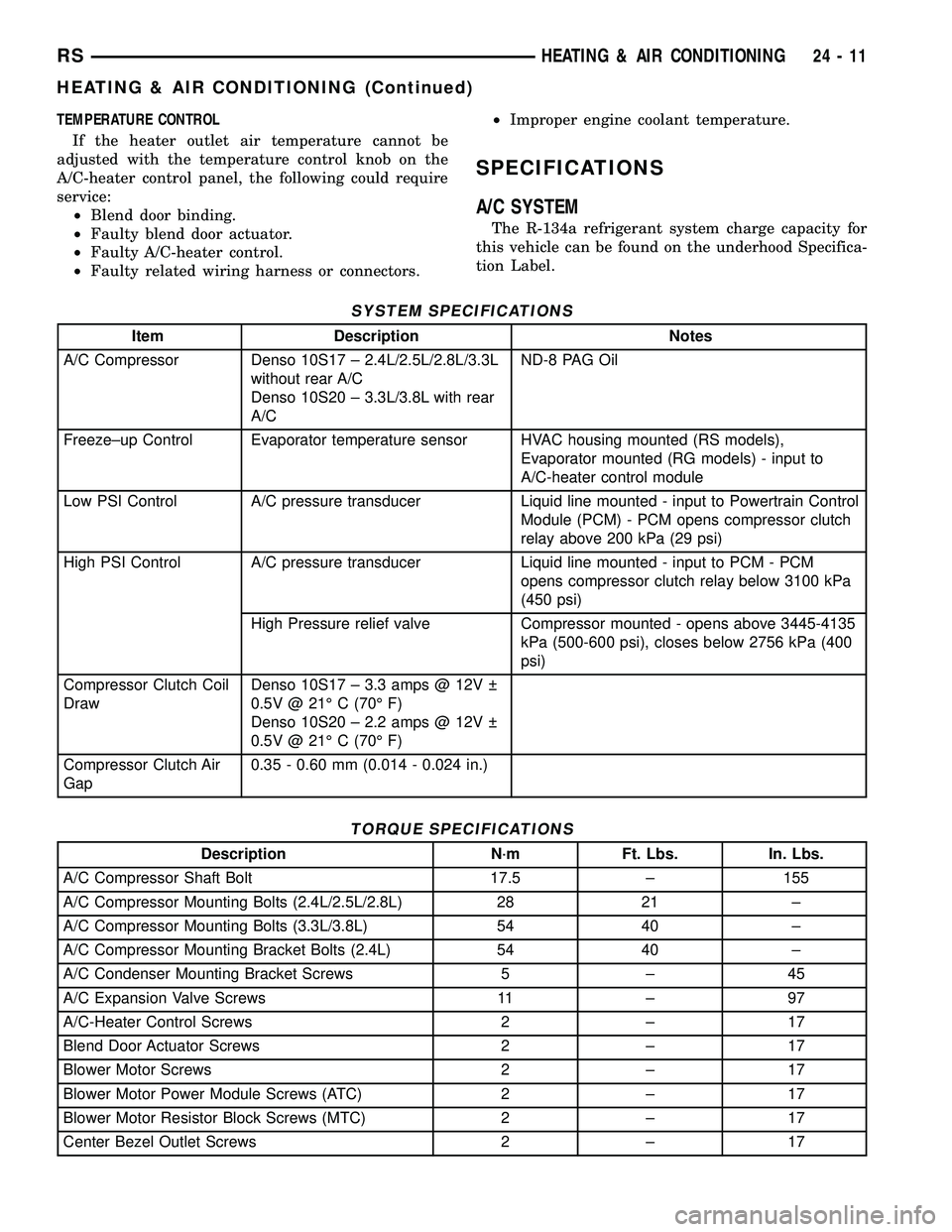
A/C SYSTEM
The R-134a refrigerant system charge capacity for
this vehicle can be found on the underhood Specifica-
tion Label.
SYSTEM SPECIFICATIONS
Item Description Notes
A/C Compressor Denso 10S17 ± 2.4L/2.5L/2.8L/3.3L
without rear A/C
Denso 10S20 ± 3.3L/3.8L with rear
A/CND-8 PAG Oil
Freeze±up Control Evaporator temperature sensor HVAC housing mounted (RS models),
Evaporator mounted (RG models) - input to
A/C-heater control module
Low PSI Control A/C pressure transducer Liquid line mounted - input to Powertrain Control
Module (PCM) - PCM opens compressor clutch
relay above 200 kPa (29 psi)
High PSI Control A/C pressure transducer Liquid line mounted - input to PCM - PCM
opens compressor clutch relay below 3100 kPa
(450 psi)
High Pressure relief valve Compressor mounted - opens above 3445-4135
kPa (500-600 psi), closes below 2756 kPa (400
psi)
Compressor Clutch Coil
DrawDenso 10S17 ± 3.3 amps @ 12V
0.5V @ 21É C (70É F)
Denso 10S20 ± 2.2 amps @ 12V
0.5V @ 21É C (70É F)
Compressor Clutch Air
Gap0.35 - 0.60 mm (0.014 - 0.024 in.)
TORQUE SPECIFICATIONS
Description N´m Ft. Lbs. In. Lbs.
A/C Compressor Shaft Bolt 17.5 ± 155
A/C Compressor Mounting Bolts (2.4L/2.5L/2.8L) 28 21 ±
A/C Compressor Mounting Bolts (3.3L/3.8L) 54 40 ±
A/C Compressor Mounting Bracket Bolts (2.4L) 54 40 ±
A/C Condenser Mounting Bracket Screws 5 ± 45
A/C Expansion Valve Screws 11 ± 97
A/C-Heater Control Screws 2 ± 17
Blend Door Actuator Screws 2 ± 17
Blower Motor Screws 2 ± 17
Blower Motor Power Module Screws (ATC) 2 ± 17
Blower Motor Resistor Block Screws (MTC) 2 ± 17
Center Bezel Outlet Screws 2 ± 17
RSHEATING & AIR CONDITIONING24-11
HEATING & AIR CONDITIONING (Continued)