2005 CHRYSLER VOYAGER CD changer
[x] Cancel search: CD changerPage 1768 of 2339
CAUTION
CAUTION: The use of tire sealants is strictly prohib-
ited for vehicles equipped with the Tire Pressure
Monitoring system. Tire sealants can clog tire pres-
sure sensors.
CAUTION: Tire pressure sensor valve stem caps
and cores are specially designed for the sensors.
Due to risk of corrosion, do not use a standard
valve stem cap or core in a tire pressure sensor in
place of the original equipment style sensor cap
and core.
CAUTION: Do not attempt to install a tire pressure
sensor in a steel wheel or aftermarket wheel. Use
tire pressure sensors in original style factory
wheels only.
NOTE: TPM thresholds have been established for
the original tire size equipped on the vehicle. Use
original size tires only to maintain system accuracy.
DIAGNOSIS AND TESTING - TIRE PRESSURE
SENSOR
NOTE: Tire pressure may increase from 2 to 6 psi
(14 to 41 kPa) during normal driving conditions. Do
NOT reduce this normal pressure build up.
If a fault in the system is detected, always check
air pressure in the tires first with a known accurate
air gauge and correct the inflation pressure. If any
tire is low, inspectallthe tires.
If the gauge-read pressure in the tires does not
indicate a tire pressure issue, refer to the appropri-
ate diagnostic information.
REMOVAL
(1) Remove tire and wheel assembly from vehicle.
(Refer to 22 - TIRES/WHEELS - REMOVAL)
CAUTION: The cap used on this valve stem con-
tains an O-ring seal to prevent contamination and
moisture from entering the valve stem. Retain this
valve stem cap for reuse. Do not substitute a regu-
lar valve stem cap in its place.
CAUTION: The valve stem used on this vehicle is
made of aluminum and the core is nickel plated
brass. The original valve stem core must be rein-
stalled and not substituted with a valve stem core
made of a different material. This is required to pre-
vent corrosion in the valve stem caused by the dif-
ferent metals.(2) Dismount tire from wheel following tire
changer manufacturers instructions while paying
special attention to the following to avoid damaging
the pressure sensor:
(a) When breaking the tire bead loose from the
wheel rim, avoid using the Bead Breaker in the
area of the sensor. That includes both front and
rear beads of the tire.
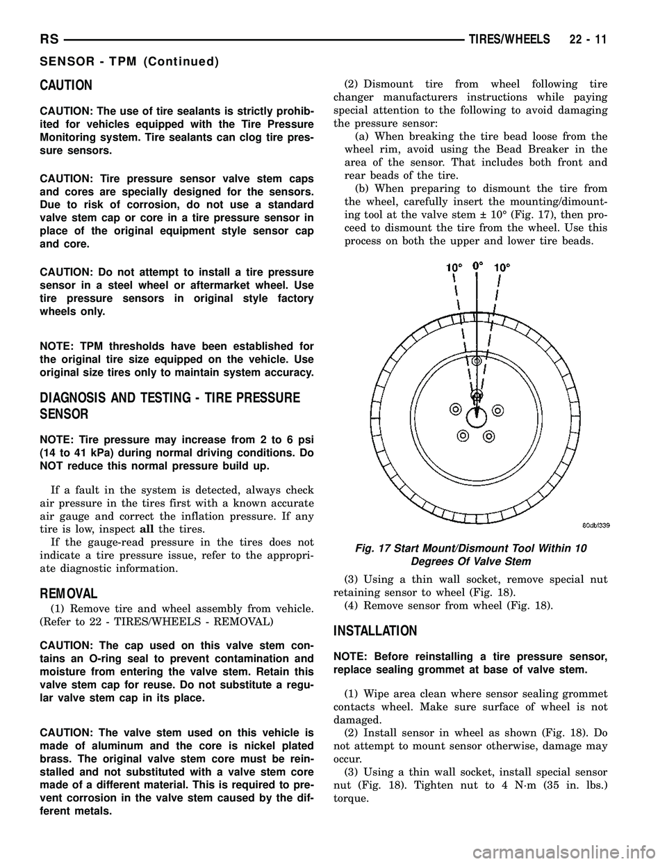
(b) When preparing to dismount the tire from
the wheel, carefully insert the mounting/dimount-
ing tool at the valve stem 10É (Fig. 17), then pro-
ceed to dismount the tire from the wheel. Use this
process on both the upper and lower tire beads.
(3) Using a thin wall socket, remove special nut
retaining sensor to wheel (Fig. 18).
(4) Remove sensor from wheel (Fig. 18).
INSTALLATION
NOTE: Before reinstalling a tire pressure sensor,
replace sealing grommet at base of valve stem.
(1) Wipe area clean where sensor sealing grommet
contacts wheel. Make sure surface of wheel is not
damaged.
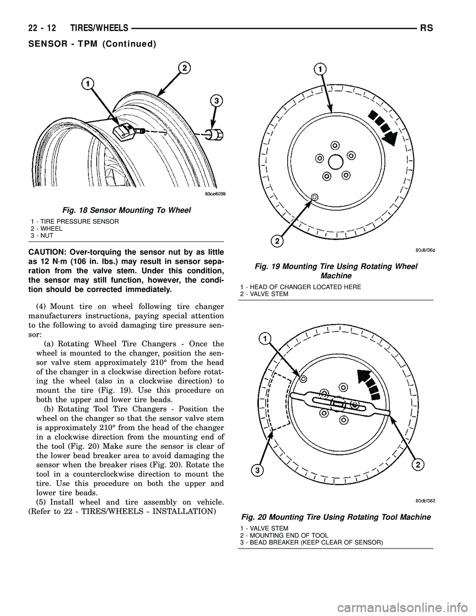
(2) Install sensor in wheel as shown (Fig. 18). Do
not attempt to mount sensor otherwise, damage may
occur.
(3) Using a thin wall socket, install special sensor
nut (Fig. 18). Tighten nut to 4 N´m (35 in. lbs.)
torque.
Fig. 17 Start Mount/Dismount Tool Within 10
Degrees Of Valve Stem
RSTIRES/WHEELS22-11
SENSOR - TPM (Continued)
Page 1769 of 2339
CAUTION: Over-torquing the sensor nut by as little
as 12 N´m (106 in. lbs.) may result in sensor sepa-
ration from the valve stem. Under this condition,
the sensor may still function, however, the condi-
tion should be corrected immediately.
(4) Mount tire on wheel following tire changer
manufacturers instructions, paying special attention
to the following to avoid damaging tire pressure sen-
sor:
(a) Rotating Wheel Tire Changers - Once the
wheel is mounted to the changer, position the sen-
sor valve stem approximately 210É from the head
of the changer in a clockwise direction before rotat-
ing the wheel (also in a clockwise direction) to
mount the tire (Fig. 19). Use this procedure on
both the upper and lower tire beads.
(b) Rotating Tool Tire Changers - Position the
wheel on the changer so that the sensor valve stem
is approximately 210É from the head of the changer
in a clockwise direction from the mounting end of
the tool (Fig. 20) Make sure the sensor is clear of
the lower bead breaker area to avoid damaging the
sensor when the breaker rises (Fig. 20). Rotate the
tool in a counterclockwise direction to mount the
tire. Use this procedure on both the upper and
lower tire beads.
(5) Install wheel and tire assembly on vehicle.
(Refer to 22 - TIRES/WHEELS - INSTALLATION)
Fig. 18 Sensor Mounting To Wheel
1 - TIRE PRESSURE SENSOR
2 - WHEEL
3 - NUT
Fig. 19 Mounting Tire Using Rotating Wheel
Machine
1 - HEAD OF CHANGER LOCATED HERE
2 - VALVE STEM
Fig. 20 Mounting Tire Using Rotating Tool Machine
1 - VALVE STEM
2 - MOUNTING END OF TOOL
3 - BEAD BREAKER (KEEP CLEAR OF SENSOR)
22 - 12 TIRES/WHEELSRS
SENSOR - TPM (Continued)
Page 2226 of 2339

²The upper bolt at the rear of the compressor.
²The lower bolt at the rear of the compressor.
(4) Connect the wire harness connector to the com-
pressor clutch coil wire connector.
(5) Install the accessory drive belt (Refer to 7 -
COOLING/ACCESSORY DRIVE/DRIVE BELTS -
INSTALLATION).
(6) Lower the vehicle.
(7) Remove the tape or plugs from the suction and
discharge line fittings and the compressor ports.
(8) Lubricate new rubber O-ring seals with clean
refrigerant oil and install them and a new gasket
onto the suction and discharge line fittings.
(9) Connect the A/C suction line and the A/C dis-
charge line to the A/C compressor.
(10) Install the nut that secures the A/C suction
line and the A/C discharge line to the A/C compres-
sor. Tighten the nuts to 23 N´m (17 ft. lbs.).
(11) Reconnect the negative battery cable.
(12) Evacuate the refrigerant system (Refer to 24 -
HEATING & AIR CONDITIONING/PLUMBING -
FRONT/REFRIGERANT - STANDARD PROCE-
DURE - REFRIGERANT SYSTEM EVACUATE).
(13) Charge the refrigerant system (Refer to 24 -
HEATING & AIR CONDITIONING/PLUMBING -
FRONT/REFRIGERANT - STANDARD PROCE-
DURE - REFRIGERANT SYSTEM CHARGE).
A/C COMPRESSOR MOUNTING BRACKET -
2.4L ENGINE
(1) Position the compressor mounting bracket onto
the engine.
(2) Install the four bolts that secure the compres-
sor mounting bracket to the engine. Tighten the bolts
to 54 N´m (40 ft. lbs.).
(3) Reinstall the A/C compressor onto the mount-
ing bracket (Refer to 24 - HEATING & AIR CONDI-
TIONING/PLUMBING/COMPRESSOR -
INSTALLATION).
A/C CONDENSER
DESCRIPTION
The A/C condenser is located in the front of the
engine compartment behind the front fascia. The A/C
condenser is a heat exchanger that allows the high-
pressure refrigerant gas being discharged by the A/C
compressor to give up its heat to the air passing over
the condenser fins, which causes the refrigerant to
cool and change to a liquid state.The A/C condenser may be removed for service
without removing the radiator and cooling fan from
the vehicle.
The A/C condenser for vehicles equipped with the
2.4L/3.3L/3.8L engines are equipped with an integral
automatic transmission cooler and mounting provi-
sions.
OPERATION
When air passes through the fins of the A/C con-
denser, the high-pressure refrigerant gas within the
A/C condenser gives up its heat. The refrigerant then
condenses as it leaves the A/C condenser and
becomes a high-pressure liquid. The volume of air
flowing over the condenser fins is critical to the
proper cooling performance of the A/C system. There-
fore, it is important that there are no objects placed
in front of the radiator grille openings at the front of
the vehicle or foreign material on the condenser fins
that might obstruct proper air flow. Also, any factory-
installed air seals or shrouds must be properly rein-
stalled following radiator or A/C condenser service.
The A/C condenser cannot be repaired and, if
faulty or damaged, it must be replaced.
Fig. 7 A/C Condenser ± 2.4L/3.3L/3.8L Engines
1 - A/C CONDENSER
2 - AUTO TRANS COOLER TAPPING BLOCK
3 - UPPER CONDENSER MOUNTING BRACKET (2)
4 - RADIATOR
5 - LOWER CONDENSER MOUNTING BRACKET (2)
RSPLUMBING - FRONT24-75
A/C COMPRESSOR (Continued)
Page 2234 of 2339
(13) Install plugs in, or tape over the opened suc-
tion line and liquid line fittings and both expansion
valve ports.
(14) Remove the two screws that secure the A/C
expansion valve to the evaporator tube tapping plate.
(15) On RG models, disconnect the HVAC wire
harness connector from the evaporator temperature
sensor.
(16) Remove the A/C expansion valve from the
evaporator inlet and outlet tube fittings.
(17) Remove the seals from the evaporator inlet
and outlet tube fittings and discard.
(18) Install plugs in, or tape over the opened evap-
orator inlet and outlet tube fittings and both expan-
sion valve ports.
(19) On RG models, remove the evaporator tem-
perature sensor retainer and evaporator temperature
sensor from the A/C expansion valve, if required.
INSTALLATION
NOTE: Any grease removed with the evaporator
temperature sensor must be replaced. Failure to do
so could result in poor A/C performance.
(1) On RG models, install the evaporator tempera-
ture sensor and retainer onto the A/C expansion
valve, if removed.
(2) Remove the tape or plugs from the evaporator
inlet and outlet tube fittings and both ports on the
back of the A/C expansion valve.(3) Lubricate new rubber O-ring seals with clean
refrigerant oil and install them on the evaporator
inlet and outlet tube fittings.
(4) Position the A/C expansion valve onto the evap-
orator inlet and outlet tube fittings.
(5) Install the two screws that secure the A/C
expansion valve to the evaporator tube tapping plate
plate. Tighten the screws to 11 N´m (97 in. lbs.).
(6) On RG models, connect the HVAC wire harness
connector to the evaporator temperature sensor.
(7) Remove the tape or plugs from the front liquid
line rear section and suction line fittings for the
expansion valve and both ports on the front of the
expansion valve.
(8) Lubricate new rubber O-ring seals with clean
refrigerant oil and install them on the front liquid
line rear section and suction line fittings for the
expansion valve.
(9) Connect the liquid line and suction line fittings
to the expansion valve.
(10) Install the nut that secures the suction line
and liquid line fittings to the stud on the expansion
valve. Tighten the nut to 23 N´m (17 ft. lbs.).
(11) Remove the tape or plugs from the liquid line
rear section fitting and the receiver/drier outlet port.
(12) Lubricate a new rubber O-ring seal with clean
refrigerant oil and install it on the liquid line fitting.
(13) Connect the liquid line fitting to the receiver/
drier outlet port.
(14) Install the screw that secures the liquid line
fitting to the receiver/drier. Tighten the screw to 11
N´m (97 in. lbs.).
(15) Connect the wire harness connector to the A/C
pressure transducer.
(16) Connect the drain tube to the wiper module
drain on the right side of the engine compartment.
(17) Install the air cleaner housing.
(18) Reconnect the battery negative cable.
(19) Evacuate the refrigerant system (Refer to 24 -
HEATING & AIR CONDITIONING/PLUMBING -
FRONT/REFRIGERANT - STANDARD PROCE-
DURE - REFRIGERANT SYSTEM EVACUATE).
(20) Charge the refrigerant system (Refer to 24 -
HEATING & AIR CONDITIONING/PLUMBING -
FRONT/REFRIGERANT - STANDARD PROCE-
DURE - REFRIGERANT SYSTEM CHARGE).
HEATER CORE
DESCRIPTION
The heater core is located in the distribution hous-
ing, which is attached to the HVAC housing, behind
the instrument panel. It is a heat exchanger made of
rows of tubes and fins. One end of the core is fitted
with a molded plastic tank, which includes integral
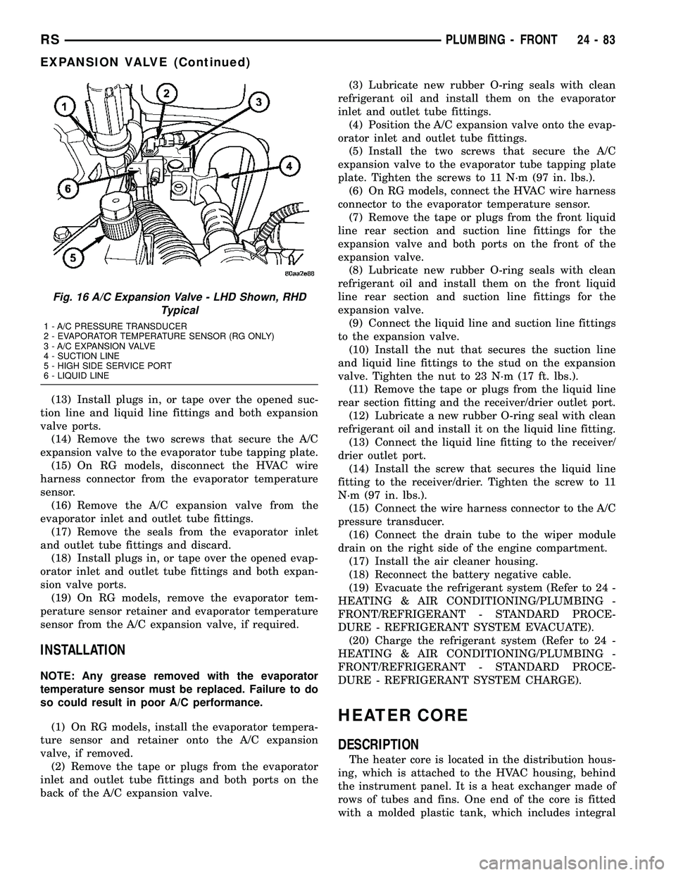
Fig. 16 A/C Expansion Valve - LHD Shown, RHD
Typical
1 - A/C PRESSURE TRANSDUCER
2 - EVAPORATOR TEMPERATURE SENSOR (RG ONLY)
3 - A/C EXPANSION VALVE
4 - SUCTION LINE
5 - HIGH SIDE SERVICE PORT
6 - LIQUID LINE
RSPLUMBING - FRONT24-83
EXPANSION VALVE (Continued)
Page 2253 of 2339
(5) Install the rear evaporator line extension onto
the expansion valve (Refer to 24 - HEATING & AIR
CONDITIONING/PLUMBING - REAR/EVAPORA-
TOR - INSTALLATION - EVAPORATOR LINE
EXTENSION).
(6) Install the foam insulator wrap over the rear
expansion valve.
(7) Install the rear HVAC housing (Refer to 24 -
HEATING & AIR CONDITIONING/DISTRIBUTION/
HVAC HOUSING - INSTALLATION).
(8) Run the HVAC Cooldown Test to verify proper
operation.
HEATER CORE
DESCRIPTION
The rear heater core is located near the front of
the rear HVAC housing, behind the right rear wheel
house. It is a heat exchanger made of rows of tubes
and fins. One end of the core is fitted with a molded
plastic tank that includes integral heater core inlet
and outlet nipples. The rear heater core can be ser-
viced without removing the rear HVAC housing from
the vehicle.
OPERATION
Engine coolant is circulated through underbody
heater hoses to the rear heater core at all times. As
the coolant flows through the rear heater core, heat
removed from the engine is transferred to the heater
core fins and tubes. Air directed through the heater
core picks up the heat from the heater core fins. The
rear blend door allows control of the rear heater out-
put air temperature by controlling how much of the
air flowing through the rear HVAC housing is
directed through the heater core.
The rear heater core cannot be repaired and, if
faulty or damaged, it must be replaced.
STANDARD PROCEDURE
REAR HEATER CORE FILLING
In its final installed position, the rear heater core
is positioned higher than the radiator fill cap. There-
fore, when the cooling system is drained and refilled,
gravity will not refill the heater core with coolant to
the proper level. This may result in two problems:1.
Insufficient coolant level in the engine cooling sys-
tem, which may result in engine overheating.2.Air
entrapped within the rear heater core, which may
result in insufficient rear heater performance. There
are two methods that may be employed to prevent
these problems:1.Pre-filling of the rear heater core.
2.Thermal cycling of the engine cooling system. Fol-lowing are descriptions of both prevention methods,
as well as a method to verify rear heater perfor-
mance.
WARNING: REFER TO THE APPLICABLE WARN-
INGS AND CAUTIONS FOR THIS SYSTEM BEFORE
PERFORMING THE FOLLOWING OPERATION (Refer
to 24 - HEATING & AIR CONDITIONING/PLUMBING
FRONT - WARNING - HEATER PLUMBING).
PRE-FILLING
If the rear heater core or the rear HVAC housing
have been removed from the vehicle for service, the
rear heater core may be pre-filled with the proper
engine coolant mixture prior to reconnecting the
heater hoses to the heater core hose fittings.
(1) The heater core should be installed in the rear
HVAC housing, and the rear HVAC housing should
be installed in the vehicle.
(2) Take the proper precautions to protect the car-
peting below the rear heater core from spilled engine
coolant and have absorbent toweling readily avail-
able to mop up any spills.
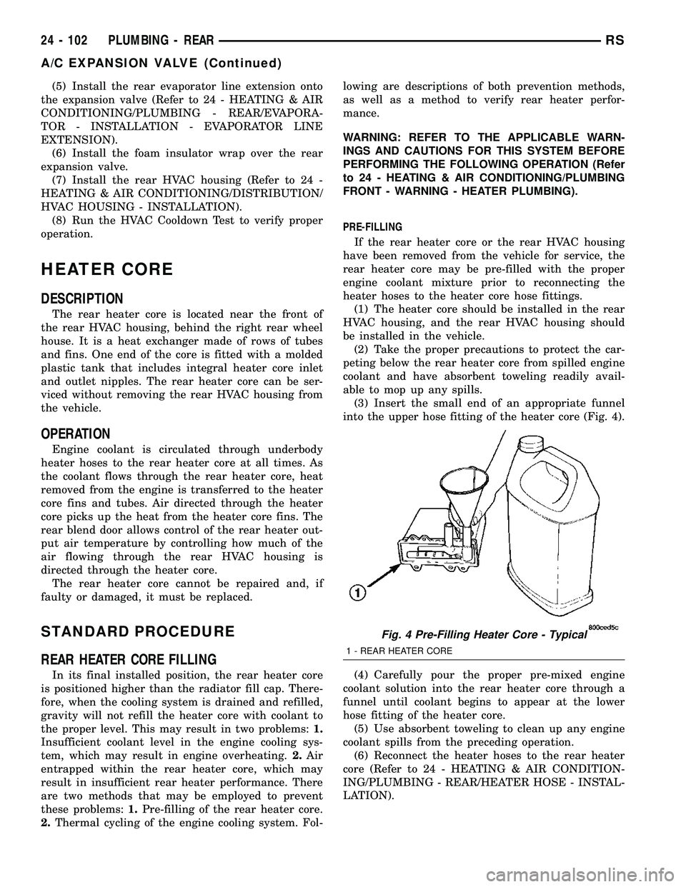
(3) Insert the small end of an appropriate funnel
into the upper hose fitting of the heater core (Fig. 4).
(4) Carefully pour the proper pre-mixed engine
coolant solution into the rear heater core through a
funnel until coolant begins to appear at the lower
hose fitting of the heater core.
(5) Use absorbent toweling to clean up any engine
coolant spills from the preceding operation.
(6) Reconnect the heater hoses to the rear heater
core (Refer to 24 - HEATING & AIR CONDITION-
ING/PLUMBING - REAR/HEATER HOSE - INSTAL-
LATION).
Fig. 4 Pre-Filling Heater Core - Typical
1 - REAR HEATER CORE
24 - 102 PLUMBING - REARRS
A/C EXPANSION VALVE (Continued)
Page 2307 of 2339
CABLE END CLEANING ANDLUBRICATION - STANDARD
PROCEDURE ......................... 5-65
CABLE RESISTANCE, SPECIFICATIONS - SPARK PLUG ......................... 8I-2
CABLES - ADJUSTMENT, PARKING BRAKE .............................. 5-65
CABLES - DESCRIPTION, BATTERY .......8F-16
CABLES - OPERATION, BATTERY ........8F-17
CABLES, DIAGNOSIS AND TESTING - BATTERY ........................... 8F-17
CALIBRATION, STANDARD PROCEDURE - A/C-HEATER CONTROL ................24-19
CALIBRATION, STANDARD PROCEDURE - COMPASS ........................... 8M-4
CALIPER - CLEANING ..............5-25,5-29
CALIPER - INSPECTION ............5-25,5-29
CALIPER - INSTALLATION, REAR DISC BRAKE .............................. 5-30
CALIPER - REMOVAL, REAR DISC BRAKE .............................. 5-28
CALIPER ADAPTER - INSTALLATION, FRONT DISC BRAKE ................... 5-31
CALIPER ADAPTER - REMOVAL, FRONT DISC BRAKE ......................... 5-31
CALIPER (CONTINENTAL TEVES BRAKES) - INSTALLATION, FRONT
DISC BRAKE ......................... 5-27
CALIPER (CONTINENTAL TEVES BRAKES) - REMOVAL, FRONT DISC
BRAKE .............................. 5-24
CALIPER GUIDE PIN BUSHINGS (CONTINENTAL TEVES BRAKES) -
ASSEMBLY ............................ 5-25
CALIPER GUIDE PIN BUSHINGS (CONTINENTAL TEVES BRAKES) -
DISASSEMBLY ........................ 5-24
CALIPER GUIDE PINS (TRW BRAKES) - INSTALLATION, DISC BRAKE ............5-32
CALIPER GUIDE PINS (TRW BRAKES) - REMOVAL, DISC BRAKE ................5-31
CALIPER PISTON AND SEAL - ASSEMBLY ...................... 5-26,5-30
CALIPER PISTON AND SEAL - DISASSEMBLY .................... 5-24,5-28
CALIPER (TRW BRAKES) - INSTALLATION, FRONT DISC BRAKE ......5-27
CALIPER (TRW BRAKES) - REMOVAL, FRONT DISC BRAKE ................... 5-24
CAMSHAFT & BEARINGS (IN BLOCK) - DESCRIPTION ....................... 9-118
CAMSHAFT & BEARINGS (IN BLOCK) - INSPECTION ........................ 9-118
CAMSHAFT & BEARINGS (IN BLOCK) - INSTALLATION ....................... 9-118
CAMSHAFT & BEARINGS (IN BLOCK) - OPERATION ......................... 9-118
CAMSHAFT & BEARINGS (IN BLOCK) - REMOVAL .......................... 9-118
CAMSHAFT END PLAY - STANDARD PROCEDURE, MEASURING ..............9-29
CAMSHAFT OIL SEAL(S) - INSTALLATION . . 9-29
CAMSHAFT OIL SEAL(S) - REMOVAL ......9-28
CAMSHAFT POSITION SENSOR - DESCRIPTION ......................... 8I-4
CAMSHAFT POSITION SENSOR - OPERATION .......................... 8I-4
CAMSHAFT SPROCKET - INSTALLATION, TIMING CHAIN ....................... 9-160
CAMSHAFT SPROCKET - REMOVAL, TIMING CHAIN ....................... 9-159
CAMSHAFT SPROCKETS - INSTALLATION . . 9-67
CAMSHAFT SPROCKETS - REMOVAL ......9-66
CAMSHAFT(S) - CLEANING ..............9-30
CAMSHAFT(S) - DESCRIPTION ...........9-29
CAMSHAFT(S) - INSPECTION ............9-30
CAMSHAFT(S) - INSTALLATION ..........9-31
CAMSHAFT(S) - OPERATION .............9-29
CAMSHAFT(S) - REMOVAL ..............9-30
CANISTER - DESCRIPTION, VAPOR ......25-19
CANISTER - INSTALLATION, REAR EVAP . . 25-21
CANISTER - OPERATION, VAPOR ........25-19
CANISTER - REMOVAL, REAR EVAP ......25-20
CAP - DESCRIPTION, FUEL FILLER .......25-13
CAP - DESCRIPTION, RADIATOR PRESSURE .......................... 7-27
CAP - INSTALLATION, INSTRUMENT PANEL RIGHT END ................... 23-72CAP - OPERATION, FUEL FILLER
........25-13
CAP - OPERATION, RADIATOR PRESSURE .......................... 7-27
CAP - REMOVAL, INSTRUMENT PANEL RIGHT END ......................... 23-72
CAP TESTING - DIAGNOSIS AND TESTING, COOLING SYSTEM
PRESSURE .......................... 7-28
CAP TO FILLER NECK SEAL - DIAGNOSIS AND TESTING, RADIATOR .....7-28
CAPACITIES - SPECIFICATIONS, FLUID ......0-6
CARE, CLEANING - WHEEL AND WHEEL TRIM .............................. 22-19
CARGO - INSTALLATION, AWD, HEAVY DUTY ............................... 2-36
CARGO - INSTALLATION, SPRING ........2-40
CARGO - REMOVAL, AWD, HEAVY DUTY . . . 2-36
CARGO - REMOVAL, SPRING ............2-40
CARPET INSERT - FOLD-IN-FLOOR - INSTALLATION, SECOND ROW FLOOR
TUB ............................... 23-98
CARPET INSERT - FOLD-IN-FLOOR - REMOVAL, SECOND ROW FLOOR TUB ....23-98
CARPET TRIM RING AND COVER - FOLD-IN-FLOOR - INSTALLATION ........23-84
CARPET TRIM RING AND COVER - FOLD-IN-FLOOR - REMOVAL ............23-84
CARPETS - FOLD-IN-FLOOR - INSTALLATION ....................... 23-83
CARPETS - FOLD-IN-FLOOR - REMOVAL . . 23-82
CARPETS AND FLOOR MATS - INSTALLATION ....................... 23-81
CARPETS AND FLOOR MATS - REMOVAL . 23-81
CARPETS INSERT - FOLD-IN-FLOOR - INSTALLATION, REAR FLOOR TUB .......23-96
CARPETS INSERT - FOLD-IN-FLOOR - REMOVAL, REAR FLOOR TUB ...........23-95
CARRIER ASSEMBLY - DESCRIPTION, BALANCE SHAFTS ..................... 9-71
CARRIER ASSEMBLY - INSTALLATION, BALANCE SHAFTS ..................... 9-73
CARRIER ASSEMBLY - OPERATION, BALANCE SHAFTS ..................... 9-71
CARRIER ASSEMBLY - REMOVAL, BALANCE SHAFTS ..................... 9-71
CATALYTIC CONVERTER - DESCRIPTION . . . 11-4
CATALYTIC CONVERTER - INSPECTION ....11-6
CATALYTIC CONVERTER - INSTALLATION . . . 11-6
CATALYTIC CONVERTER - OPERATION .....11-4
CATALYTIC CONVERTER - REMOVAL ......11-5
CAUTION, A/C SYSTEM ................24-66
CAUTION, DESCRIPTION .................5-4
CAUTION, DESCRIPTION ...............19-37
CAUTION, OPERATION .................5-90
CAUTION, SENSOR - TPM ..............22-11
CAUTIONS, WARNING - WARNINGS . 19-10,19-26
CD CHANGER - DESCRIPTION ..........8A-11
CD CHANGER - INSTALLATION ..........8A-11
CD CHANGER - OPERATION ............8A-11
CD CHANGER - REMOVAL .............8A-11
CENTER - DESCRIPTION, ELECTRONIC VEHICLE INFO ....................... 8M-7
CENTER - INSTALLATION, MESSAGE ......8M-1
CENTER - OPERATION, ELECTRONIC VEHICLE INFO ....................... 8M-7
CENTER - REMOVAL, MESSAGE .........8M-1
CENTER BEZEL - INSTALLATION, INSTRUMENT PANEL .................. 23-72
CENTER BEZEL - REMOVAL, INSTRUMENT PANEL .................. 23-71
CENTER BEZEL OUTLETS, INSTALLATION - FRONT ............................ 24-45
CENTER BEZEL OUTLETS, REMOVAL - FRONT ............................. 24-44
CENTER CONSOLE LAMP - INSTALLATION ....................... 8L-21
CENTER CONSOLE LAMP - REMOVAL ....8L-21
CENTER CONSOLE LAMP SWITCH - INSTALLATION ....................... 8L-21
CENTER CONSOLE LAMP SWITCH - REMOVAL .......................... 8L-21
CENTER, DIAGNOSIS AND TESTING - ELECTRONIC VEHICLE INFORMATION .....8M-8
CENTER HIGH MOUNTED STOP LAMP - INSTALLATION ........................ 8L-6
CENTER HIGH MOUNTED STOP LAMP - REMOVAL ........................... 8L-6CENTER HIGH MOUNTED STOP LAMP
UNIT - INSTALLATION .................. 8L-6
CENTER HIGH MOUNTED STOP LAMP UNIT - REMOVAL ..................... 8L-6
CENTER HINGE - INSTALLATION .........23-24
CENTER HINGE - REMOVAL ............23-24
CENTER LAP BELT - FOLD-IN-FLOOR - INSTALLATION, SEAT BELT ............23-157
CENTER LAP BELT - FOLD-IN-FLOOR - REMOVAL, SEAT BELT ................23-157
CENTER PROGRAMMING, STANDARD PROCEDURE - ELECTRONIC VEHICLE
INFORMATION ....................... 8M-8
CENTER STRIKER - INSTALLATION .......23-28
CENTER STRIKER - REMOVAL ..........23-28
CENTERING - STANDARD PROCEDURE, CLOCKSPRING ...................... 8O-11
CHAIN AND CAMSHAFT SPROCKET - INSTALLATION, TIMING ................9-160
CHAIN AND CAMSHAFT SPROCKET - REMOVAL, TIMING ................... 9-159
CHAIN COVER - INSTALLATION, TIMING . . 9-157
CHAIN COVER - REMOVAL, TIMING ......9-156
CHAIN WEAR - STANDARD PROCEDURE, MEASURING TIMING .................. 9-155
CHANGE - STANDARD PROCEDURE, ENGINE OIL AND FILTER ...........9-139,9-54
CHANGER - DESCRIPTION, CD ..........8A-11
CHANGER - INSTALLATION, CD .........8A-11
CHANGER - OPERATION, CD ............8A-11
CHANGER - REMOVAL, CD ..............8A-11
CHANNEL - INSTALLATION, WATER .....23-174
CHANNEL - REMOVAL, WATER .........23-174
CHARGE LEVEL TEST, DIAGNOSIS AND TESTING - SYSTEM ................... 24-67
CHARGE, STANDARD PROCEDURE - REFRIGERANT SYSTEM ...............24-71
CHARGING, STANDARD PROCEDURE - CONVENTIONAL BATTERY ..............8F-11
CHARGING, STANDARD PROCEDURE - SPIRAL PLATE BATTERY ...............8F-10
CHARGING SYSTEM - DESCRIPTION .....8F-21
CHARGING SYSTEM - OPERATION .......8F-21
CHARTS - DIAGNOSIS AND TESTING, STEERING SYSTEM DIAGNOSIS ..........19-3
CHARTS - SPECIFICATIONS, COLOR CODE ............................. 23-100
CHECK - DIAGNOSIS AND TESTING, COOLING SYSTEM FLOW ................7-3
CHECK - DIAGNOSIS AND TESTING, EXHAUST SYSTEM RESTRICTION .........11-2
CHECK - STANDARD PROCEDURE, COOLANT LEVEL .......................7-4
CHECK - STANDARD PROCEDURE, ENGINE OIL LEVEL ................... 9-140
CHECK, STANDARD PROCEDURE - ENGINE OIL LEVEL .................... 9-54
CHECK, STANDARD PROCEDURE - FLUID LEVEL AND CONDITION .........21-230,21-82
CHECK STRAP - INSTALLATION .........23-15
CHECK STRAP - REMOVAL .............23-15
CHECKING - STANDARD PROCEDURE, BRAKE FLUID LEVEL ................... 5-33
CHECKING - STANDARD PROCEDURE, POWER STEERING FLUID LEVEL ........19-44
CHECKING BATTERY ELECTROLYTE LEVEL, STANDARD PROCEDURE .........8F-14
CHECKING ENGINE OIL PRESSURE - DIAGNOSIS AND TESTING ..............9-53
CHECKING POWER STEERING BELT TENSION - STANDARD PROCEDURE .......7-8
CHILD RESTRAINT ANCHOR - DESCRIPTION ........................ 8O-9
CHILD RESTRAINT ANCHOR - OPERATION ......................... 8O-10
CHILD SEAT - INSTALLATION, QUAD ....23-106
CHILD SEAT - REMOVAL, QUAD ........23-106
CHILD SEAT MODULE, BENCH SEAT - REMOVAL ......................... 23-104
CHIME SYSTEM - DIAGNOSIS AND TESTING ............................ 8B-2
CHIME/BUZZER - DESCRIPTION ..........8B-1
CHIME/BUZZER - OPERATION ............8B-1
CHIME/BUZZER - WARNING .............8B-2
CHIME/THERMISTOR - DESCRIPTION .....8N-8
CHIME/THERMISTOR - INSTALLATION .....8N-9
CHIME/THERMISTOR - OPERATION .......8N-8
CHIME/THERMISTOR - REMOVAL ........8N-8
6 INDEXRS
Description Group-Page Description Group-Page Description Group-Page