2005 CHRYSLER VOYAGER power modul
[x] Cancel search: power modulPage 2171 of 2339
REMOVAL
WARNING: ON VEHICLES EQUIPPED WITH AIR-
BAGS, DISABLE THE AIRBAG SYSTEM BEFORE
ATTEMPTING ANY STEERING WHEEL, STEERING
COLUMN, OR INSTRUMENT PANEL COMPONENT
DIAGNOSIS OR SERVICE. DISCONNECT AND ISO-
LATE THE BATTERY NEGATIVE (GROUND) CABLE,
THEN WAIT TWO MINUTES FOR THE AIRBAG SYS-
TEM CAPACITOR TO DISCHARGE BEFORE PER-
FORMING FURTHER DIAGNOSIS OR SERVICE. THIS
IS THE ONLY SURE WAY TO DISABLE THE AIRBAG
SYSTEM. FAILURE TO TAKE THE PROPER PRE-
CAUTIONS COULD RESULT IN ACCIDENTAL AIR-
BAG DEPLOYMENT AND POSSIBLE PERSONAL
INJURY.
(1) Disconnect and isolate the battery negative
cable.
(2) Remove the center bezel from the instrument
panel (Refer to 23 - BODY/INSTRUMENT PANEL/
INSTRUMENT PANEL CENTER BEZEL -
REMOVAL).
(3) Place the instrument panel center bezel unit
face down on a suitable work surface. Take the
proper precautions to protect the center bezel from
cosmetic damage.
(4) If the vehicle is equipped with the optional
Automatic Temperature Control (ATC) system, dis-
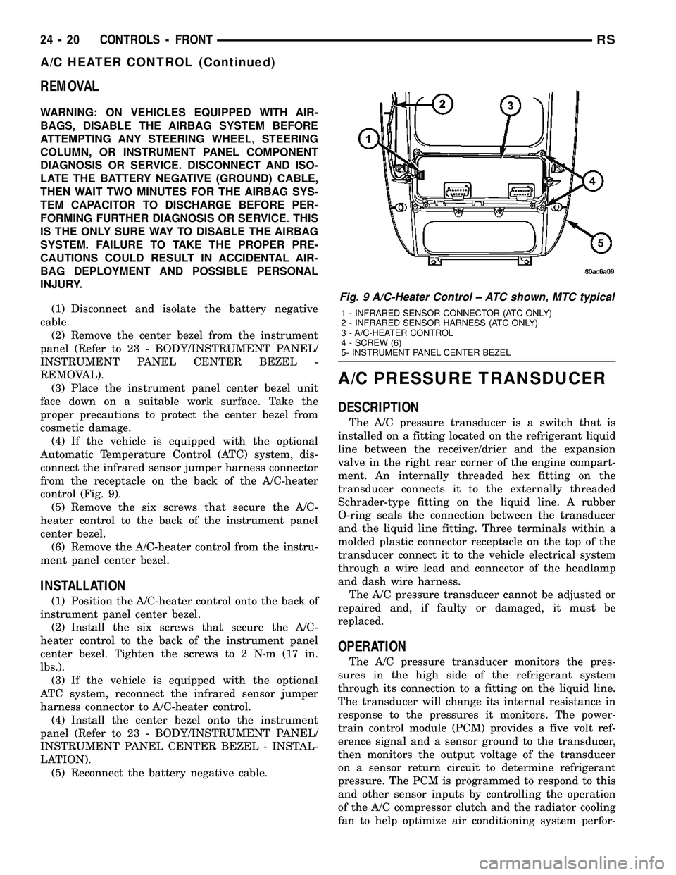
connect the infrared sensor jumper harness connector
from the receptacle on the back of the A/C-heater
control (Fig. 9).
(5) Remove the six screws that secure the A/C-
heater control to the back of the instrument panel
center bezel.
(6) Remove the A/C-heater control from the instru-
ment panel center bezel.
INSTALLATION
(1) Position the A/C-heater control onto the back of
instrument panel center bezel.
(2) Install the six screws that secure the A/C-
heater control to the back of the instrument panel
center bezel. Tighten the screws to 2 N´m (17 in.
lbs.).
(3) If the vehicle is equipped with the optional
ATC system, reconnect the infrared sensor jumper
harness connector to A/C-heater control.
(4) Install the center bezel onto the instrument
panel (Refer to 23 - BODY/INSTRUMENT PANEL/
INSTRUMENT PANEL CENTER BEZEL - INSTAL-
LATION).
(5) Reconnect the battery negative cable.
A/C PRESSURE TRANSDUCER
DESCRIPTION
The A/C pressure transducer is a switch that is
installed on a fitting located on the refrigerant liquid
line between the receiver/drier and the expansion
valve in the right rear corner of the engine compart-
ment. An internally threaded hex fitting on the
transducer connects it to the externally threaded
Schrader-type fitting on the liquid line. A rubber
O-ring seals the connection between the transducer
and the liquid line fitting. Three terminals within a
molded plastic connector receptacle on the top of the
transducer connect it to the vehicle electrical system
through a wire lead and connector of the headlamp
and dash wire harness.
The A/C pressure transducer cannot be adjusted or
repaired and, if faulty or damaged, it must be
replaced.
OPERATION
The A/C pressure transducer monitors the pres-
sures in the high side of the refrigerant system
through its connection to a fitting on the liquid line.
The transducer will change its internal resistance in
response to the pressures it monitors. The power-
train control module (PCM) provides a five volt ref-
erence signal and a sensor ground to the transducer,
then monitors the output voltage of the transducer
on a sensor return circuit to determine refrigerant
pressure. The PCM is programmed to respond to this
and other sensor inputs by controlling the operation
of the A/C compressor clutch and the radiator cooling
fan to help optimize air conditioning system perfor-
Fig. 9 A/C-Heater Control ± ATC shown, MTC typical
1 - INFRARED SENSOR CONNECTOR (ATC ONLY)
2 - INFRARED SENSOR HARNESS (ATC ONLY)
3 - A/C-HEATER CONTROL
4 - SCREW (6)
5- INSTRUMENT PANEL CENTER BEZEL
24 - 20 CONTROLS - FRONTRS
A/C HEATER CONTROL (Continued)
Page 2172 of 2339
mance and to protect the system components from
damage. The A/C pressure transducer input to the
PCM will also prevent the A/C compressor clutch
from engaging when ambient temperatures are below
about 4.5É C (40É F) due to the pressure/temperature
relationship of the refrigerant. The Schrader-type
valve in the liquid line fitting permits the A/C pres-
sure transducer to be removed or installed without
disturbing the refrigerant in the system. The A/C
pressure transducer is diagnosed using a DRBIIIt
scan tool. Refer to Body Diagnostic Procedures.
DIAGNOSIS AND TESTING
A/C PRESSURE TRANSDUCER
The A/C pressure transducer is tested using a
DRBIIItscan tool. Refer to the appropriate diagnos-
tic information. Before testing the A/C pressure
transducer, be certain that the transducer wire har-
ness connection is clean of corrosion and properly
connected. For the A/C to operate, an A/C pressure
transducer voltage reading between 0.451 and 4.519
volts is required. Voltages outside this range indicate
a low or high refrigerant system pressure condition
to the powertrain control module (PCM). The PCM is
programmed to respond to a low or high refrigerant
system pressure by suppressing operation of the A/C
compressor. Refer to the A/C Pressure Transducer
Voltage chart for the possible conditions indicated by
the transducer voltage reading.
A/C PRESSURE TRANSDUCER VOLTAGE
Voltage Possible Indication
0.0 1. No sensor supply voltage from
PCM.
2. Shorted sensor circuit.
3. Faulty transducer.
0.150 TO 0.450 1. Ambient temperature below
10É C (50É F).
2. Low refrigerant system
pressure.
0.451 TO 4.519 1. Normal refrigerant system
pressure.
4.520 TO 4.850 1. High refrigerant system
pressure.
5.0 1. Open sensor circuit.
2. Faulty transducer.
REMOVAL
NOTE: Note: It is not necessary to discharge the
refrigerant system to replace the A/C pressure
transducer.
(1) Disconnect and isolate the battery negative
cable.
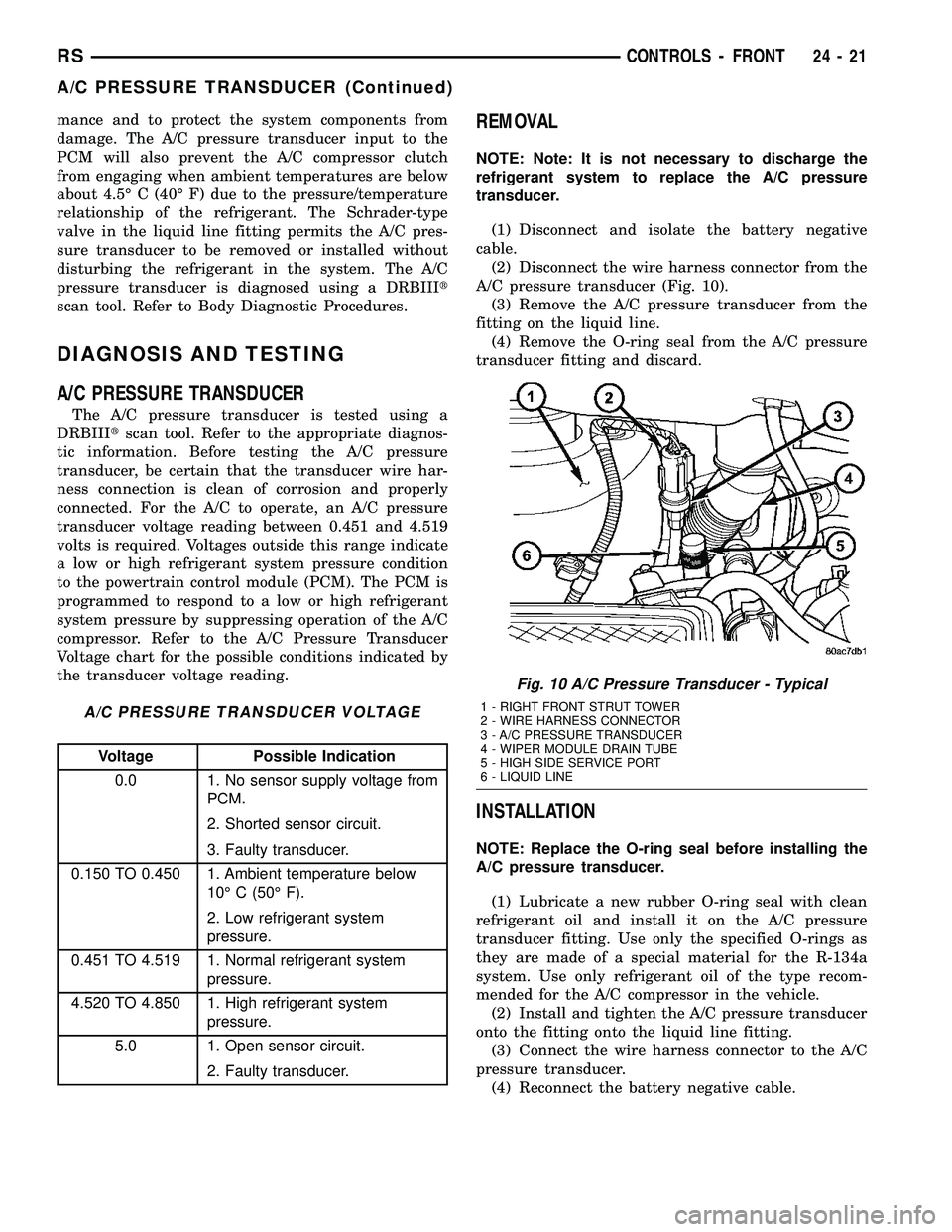
(2) Disconnect the wire harness connector from the
A/C pressure transducer (Fig. 10).
(3) Remove the A/C pressure transducer from the
fitting on the liquid line.
(4) Remove the O-ring seal from the A/C pressure
transducer fitting and discard.
INSTALLATION
NOTE: Replace the O-ring seal before installing the
A/C pressure transducer.
(1) Lubricate a new rubber O-ring seal with clean
refrigerant oil and install it on the A/C pressure
transducer fitting. Use only the specified O-rings as
they are made of a special material for the R-134a
system. Use only refrigerant oil of the type recom-
mended for the A/C compressor in the vehicle.
(2) Install and tighten the A/C pressure transducer
onto the fitting onto the liquid line fitting.
(3) Connect the wire harness connector to the A/C
pressure transducer.
(4) Reconnect the battery negative cable.
Fig. 10 A/C Pressure Transducer - Typical
1 - RIGHT FRONT STRUT TOWER
2 - WIRE HARNESS CONNECTOR
3 - A/C PRESSURE TRANSDUCER
4 - WIPER MODULE DRAIN TUBE
5 - HIGH SIDE SERVICE PORT
6 - LIQUID LINE
RSCONTROLS - FRONT24-21
A/C PRESSURE TRANSDUCER (Continued)
Page 2174 of 2339

(3) Connect the HVAC wire harness connector to
the blend door actuator.
(4) Install the silencer under the driver side end of
the instrument panel (Refer to 23 - BODY/INSTRU-
MENT PANEL/INSTRUMENT PANEL SILENCER -
INSTALLATION).
(5) Reconnect the battery negative cable.
(6) Perform the heater-A/C control calibration pro-
cedure (Refer to 24 - HEATING & AIR CONDITION-
ING/CONTROLS - FRONT/A/C-HEATER CONTROL
- STANDARD PROCEDURE - HEATER-A/C CON-
TROL CALIBRATION).
BLOWER MOTOR RELAY
DESCRIPTION
The front blower motor relay is an International
Standards Organization (ISO)-type relay (Fig. 12).
Relays conforming to the ISO specifications have
common physical dimensions, current capacities, ter-
minal patterns, and terminal functions. The front
blower motor relay is located in the integrated power
module (IPM) in the engine compartment. See the
fuse and relay map on the inner surface of the cover
of the IPM for front blower motor relay identification
and location.
The black, molded plastic case is the most visible
component of the front blower motor relay. Five male
spade-type terminals extend from the bottom of the
base to connect the relay to the vehicle electrical sys-
tem, and the ISO designation for each terminal ismolded into the base adjacent to each terminal. The
ISO terminal designations are as follows:
²30 (Common Feed)- This terminal is con-
nected to the movable contact point of the relay.
²85 (Coil Ground)- This terminal is connected
to the ground feed side of the relay control coil.
²86 (Coil Battery)- This terminal is connected
to the battery feed side of the relay control coil.
²87 (Normally Open)- This terminal is con-
nected to the normally open fixed contact point of the
relay.
²87A (Normally Closed)- This terminal is con-
nected to the normally closed fixed contact point of
the relay.
The front blower motor relay cannot be adjusted or
repaired. If the relay is damaged or faulty, it must be
replaced.
OPERATION
The blower motor relay is an electromechanical
switch that uses a low current input from the Front
Control Module (FCM) to control the high current
output to the blower motor resistor (manual heater-
A/C control) or blower power module (ATC control).
The movable common feed contact point is held
against the fixed normally closed contact point by
spring pressure. When the relay coil is energized, an
electromagnetic field is produced by the coil wind-
ings. This electromagnetic field draws the movable
relay contact point away from the fixed normally
closed contact point, and holds it against the fixed
normally open contact point. When the relay coil is
de-energized, spring pressure returns the movable
contact point back against the fixed normally closed
contact point. The resistor or diode is connected in
parallel with the relay coil in the relay, and helps to
dissipate voltage spikes and electromagnetic interfer-
ence that can be generated as the electromagnetic
field of the relay coil collapses.
Fig. 11 Blend Door Actuator - LHD Shown, RHD
Typical
1 - WIRE HARNESS CONNECTOR
2 - MODE DOOR ACTUATOR
3 - SCREW (2)
4 - DRIVER BLEND DOOR ACTUATOR (DUAL-ZONE)
5 - HEATER CORE
6 - BLEND DOOR ACTUATOR (SINGLE ZONE) OR PASSENGER
BLEND DOOR ACTUATOR (DUAL-ZONE)
Fig. 12 Front Blower Motor Relay
RSCONTROLS - FRONT24-23
BLEND DOOR ACTUATOR (Continued)
Page 2175 of 2339
The blower motor relay terminals are connected to
the vehicle electrical system through a receptacle in
the Integrated Power Module (IPM). The inputs and
outputs of the blower motor relay include:
²The common feed terminal (30) receives a bat-
tery current input from the battery through a B(+)
circuit at all times.
²The coil ground terminal (85) receives a ground
input through the front/rear blower motor relay con-
trol circuit only when the FCM electronically pulls
the control circuit to ground.
²The coil battery terminal (86) receives a battery
current input from the battery through a B(+) circuit
at all times.
²The normally open terminal (87) provides a bat-
tery current output to the blower motor resistor
(manual heater-A/C control) or blower power module
(automatic heater-A/C control) through a fuse in the
IPM on the fused front blower motor relay output cir-
cuit only when the blower motor relay coil is ener-
gized.
²The normally closed terminal (87A) is not con-
nected to any circuit in this application, but provides
a battery current output only when the blower motor
relay coil is de-energized.
Refer to the appropriate wiring information for
diagnosis and testing of the micro-relay and for com-
plete HVAC wiring diagrams.
REMOVAL
(1) Disconnect and isolate the negative battery
cable.
(2) Remove the cover from the integrated power
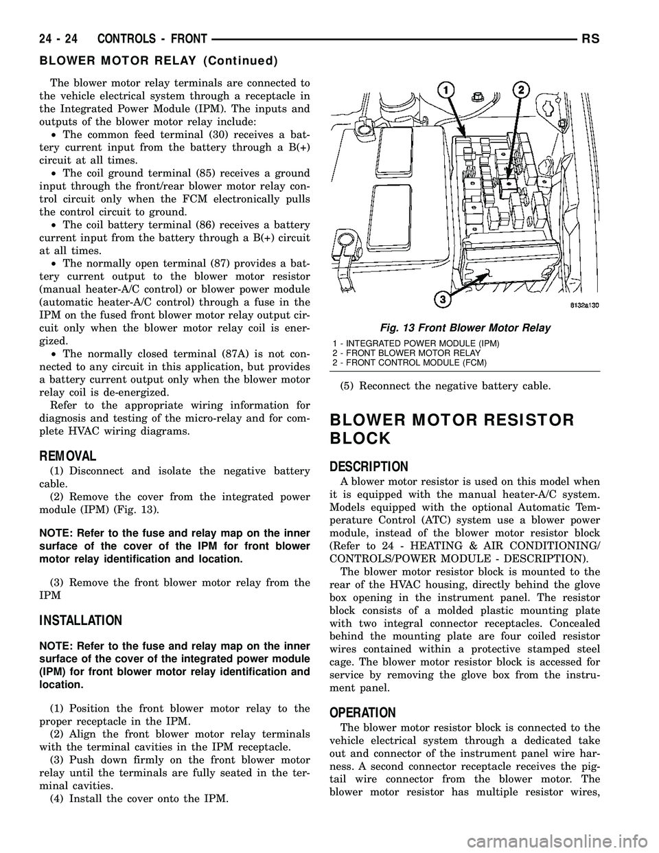
module (IPM) (Fig. 13).
NOTE: Refer to the fuse and relay map on the inner
surface of the cover of the IPM for front blower
motor relay identification and location.
(3) Remove the front blower motor relay from the
IPM
INSTALLATION
NOTE: Refer to the fuse and relay map on the inner
surface of the cover of the integrated power module
(IPM) for front blower motor relay identification and
location.
(1) Position the front blower motor relay to the
proper receptacle in the IPM.
(2) Align the front blower motor relay terminals
with the terminal cavities in the IPM receptacle.
(3) Push down firmly on the front blower motor
relay until the terminals are fully seated in the ter-
minal cavities.
(4) Install the cover onto the IPM.(5) Reconnect the negative battery cable.
BLOWER MOTOR RESISTOR
BLOCK
DESCRIPTION
A blower motor resistor is used on this model when
it is equipped with the manual heater-A/C system.
Models equipped with the optional Automatic Tem-
perature Control (ATC) system use a blower power
module, instead of the blower motor resistor block
(Refer to 24 - HEATING & AIR CONDITIONING/
CONTROLS/POWER MODULE - DESCRIPTION).
The blower motor resistor block is mounted to the
rear of the HVAC housing, directly behind the glove
box opening in the instrument panel. The resistor
block consists of a molded plastic mounting plate
with two integral connector receptacles. Concealed
behind the mounting plate are four coiled resistor
wires contained within a protective stamped steel
cage. The blower motor resistor block is accessed for
service by removing the glove box from the instru-
ment panel.
OPERATION
The blower motor resistor block is connected to the
vehicle electrical system through a dedicated take
out and connector of the instrument panel wire har-
ness. A second connector receptacle receives the pig-
tail wire connector from the blower motor. The
blower motor resistor has multiple resistor wires,
Fig. 13 Front Blower Motor Relay
1 - INTEGRATED POWER MODULE (IPM)
2 - FRONT BLOWER MOTOR RELAY
2 - FRONT CONTROL MODULE (FCM)
24 - 24 CONTROLS - FRONTRS
BLOWER MOTOR RELAY (Continued)
Page 2178 of 2339
The evaporator temperature sensor cannot be
adjusted or repaired and, if faulty or damaged, it
must be replaced.
OPERATION
The evaporator temperature sensor monitors the
temperature of the conditioned air once it passes
through the A/C evaporator. The evaporator temper-
ature sensor will change its internal resistance in
response to the air temperatures it monitors and is
connected to the A/C-heater control through sensor
ground and signal circuits. As the conditioned air
temperature increases, the resistance of the evapora-
tor temperature sensor decreases and the voltage
monitored by the A/C-heater control decreases. The
external location of the evaporator temperature sen-
sor allows the sensor to be removed or installed with-
out disturbing the refrigerant in the A/C system.
The A/C-heater control uses this monitored voltage
reading as an indication of the evaporator tempera-
ture. The A/C-heater control is programmed to
respond to this input by sending electronic messages
to the powertrain control module (PCM) over the con-
troller area network (CAN) data bus. The PCM then
cycles the A/C compressor clutch as necessary to opti-
mize A/C system performance and to protect the A/C
system from evaporator freezing.
The evaporator temperature sensor cannot be
adjusted or repaired and, if faulty or damaged, it
must be replaced.
The evaporator temperature sensor is diagnosed
using the DRBIIItscan tool. Refer to Body Diagnos-
tic Procedures.
REMOVAL
RG MODELS
(1) Disconnect and isolate the battery negative
cable.
(2) Remove the air cleaner housing from the right
side of the engine compartment.
(3) Remove the windshield wiper assembly from
the vehicle (Refer to 8 - ELECTRICAL/WIPERS/
WASHERS/WIPER MODULE - REMOVAL).
(4) Remove the temperature sensor retainer from
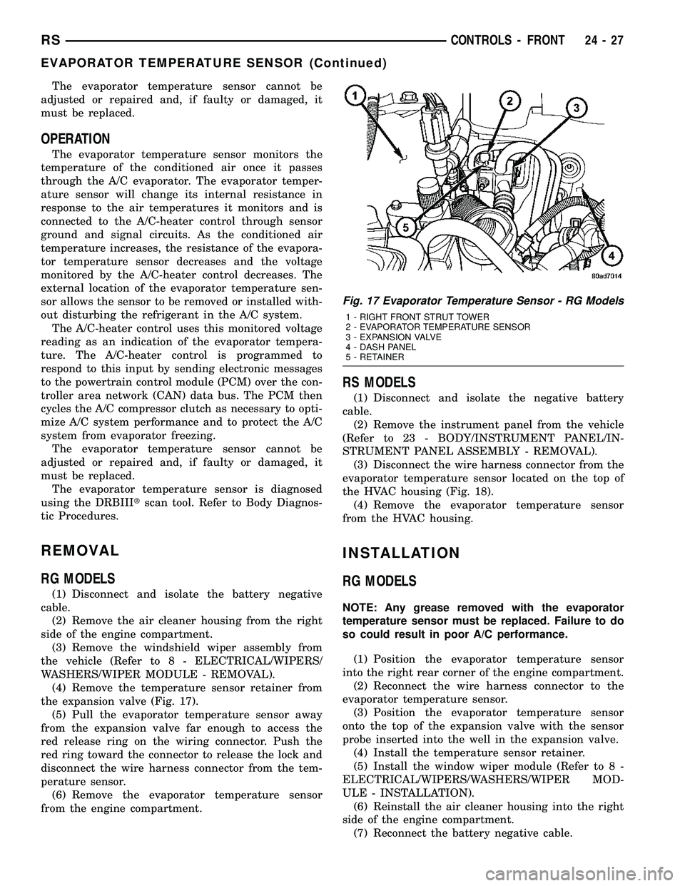
the expansion valve (Fig. 17).
(5) Pull the evaporator temperature sensor away
from the expansion valve far enough to access the
red release ring on the wiring connector. Push the
red ring toward the connector to release the lock and
disconnect the wire harness connector from the tem-
perature sensor.
(6) Remove the evaporator temperature sensor
from the engine compartment.
RS MODELS
(1) Disconnect and isolate the negative battery
cable.
(2) Remove the instrument panel from the vehicle
(Refer to 23 - BODY/INSTRUMENT PANEL/IN-
STRUMENT PANEL ASSEMBLY - REMOVAL).
(3) Disconnect the wire harness connector from the
evaporator temperature sensor located on the top of
the HVAC housing (Fig. 18).
(4) Remove the evaporator temperature sensor
from the HVAC housing.
INSTALLATION
RG MODELS
NOTE: Any grease removed with the evaporator
temperature sensor must be replaced. Failure to do
so could result in poor A/C performance.
(1) Position the evaporator temperature sensor
into the right rear corner of the engine compartment.
(2) Reconnect the wire harness connector to the
evaporator temperature sensor.
(3) Position the evaporator temperature sensor
onto the top of the expansion valve with the sensor
probe inserted into the well in the expansion valve.
(4) Install the temperature sensor retainer.
(5) Install the window wiper module (Refer to 8 -
ELECTRICAL/WIPERS/WASHERS/WIPER MOD-
ULE - INSTALLATION).
(6) Reinstall the air cleaner housing into the right
side of the engine compartment.
(7) Reconnect the battery negative cable.
Fig. 17 Evaporator Temperature Sensor - RG Models
1 - RIGHT FRONT STRUT TOWER
2 - EVAPORATOR TEMPERATURE SENSOR
3 - EXPANSION VALVE
4 - DASH PANEL
5 - RETAINER
RSCONTROLS - FRONT24-27
EVAPORATOR TEMPERATURE SENSOR (Continued)
Page 2181 of 2339
INSTALLATION
(1) Position the mode door actuator onto the HVAC
distribution housing. If necessary, rotate the actuator
slightly to align the splines on the actuator output
shaft with those in the mode door linkage.
(2) Install the two screws that secure the mode
door actuator to the distribution housing. Tighten the
screws to 2 N´m (17 in. lbs.).
(3) Connect the wire harness connector to the
mode door actuator.
(4) Install the silencer under the driver side end of
the instrument panel (Refer to 23 - BODY/INSTRU-
MENT PANEL/INSTRUMENT PANEL SILENCER -
INSTALLATION).
(5) Reconnect the negative battery cable.
(6) Perform the A/C-heater control calibration pro-
cedure (Refer to 24 - HEATING & AIR CONDITION-
ING/CONTROLS - FRONT/A/C-HEATER CONTROL
- STANDARD PROCEDURE - HEATER-A/C CON-
TROL CALIBRATION).
POWER MODULE - BLOWER
MOTOR
DESCRIPTION
A blower motor power module is used on this
model when it is equipped with the optional Auto-
matic Temperature Control (ATC) system. Models
equipped with the standard manual heater-A/C sys-
tem use a blower motor resistor block, instead of the
blower motor power module (Refer to 24 - HEATING
& AIR CONDITIONING/CONTROLS/BLOWER
MOTOR RESISTOR BLOCK - DESCRIPTION).
The blower motor power module is mounted to the
rear of the HVAC housing, directly behind the glove
box opening in the instrument panel. The module
consists of a molded plastic mounting plate with two
integral connector receptacles. Concealed behind the
mounting plate is the power module electronic cir-
cuitry and a large finned, heat sink. The blower
motor power module is accessed for service by remov-
ing the glove box from the instrument panel.
OPERATION
The blower motor power module is connected to the
vehicle electrical system through a dedicated lead
and connector from the instrument panel wire har-
ness. A second connector receptacle receives a wire
lead connector from the blower motor. The blower
motor power module allows the microprocessor-based
Automatic Temperature Control (ATC) heater-A/C
control module to calculate and provide infinitely
variable blower motor speeds based upon either man-
ual blower switch input or the ATC programming
using a Pulse Width Modulated (PWM) circuit strat-
egy. The PWM voltage is applied to a comparator cir-
cuit which compares the PWM signal voltage to the
blower motor feedback voltage. The resulting output
drives the power module circuitry, which adjusts the
voltage output received from the blower motor relay
to change or maintain the desired blower speed. The
blower motor power module is diagnosed using a
DRBIIItscan tool. Refer to Body Diagnostic Proce-
dures.
REMOVAL
WARNING: ON VEHICLES EQUIPPED WITH AIR-
BAGS, DISABLE THE AIRBAG SYSTEM BEFORE
ATTEMPTING ANY STEERING WHEEL, STEERING
COLUMN, OR INSTRUMENT PANEL COMPONENT
DIAGNOSIS OR SERVICE. DISCONNECT AND ISO-
LATE THE BATTERY NEGATIVE (GROUND) CABLE,
THEN WAIT TWO MINUTES FOR THE AIRBAG SYS-
TEM CAPACITOR TO DISCHARGE BEFORE PER-
FORMING FURTHER DIAGNOSIS OR SERVICE. THIS
IS THE ONLY SURE WAY TO DISABLE THE AIRBAG
SYSTEM. FAILURE TO TAKE THE PROPER PRE-
CAUTIONS COULD RESULT IN ACCIDENTAL AIR-
BAG DEPLOYMENT AND POSSIBLE PERSONAL
INJURY.
WARNING: THE HEAT SINK FOR THE BLOWER
MOTOR POWER MODULE MAY GET VERY HOT
DURING NORMAL OPERATION. IF THE BLOWER
MOTOR WAS TURNED ON PRIOR TO SERVICING
THE BLOWER MOTOR POWER MODULE, WAIT
FIVE MINUTES TO ALLOW THE HEAT SINK TO
COOL BEFORE PERFORMING DIAGNOSIS OR SER-
VICE. FAILURE TO TAKE THIS PRECAUTION CAN
RESULT IN PERSONAL INJURY.
24 - 30 CONTROLS - FRONTRS
MODE DOOR ACTUATOR (Continued)
Page 2182 of 2339
(1) Disconnect and isolate the negative battery
cable.
(2) Remove the glove box from the instrument
panel (Refer to 23 - BODY/INSTRUMENT PANEL/
GLOVE BOX - REMOVAL).
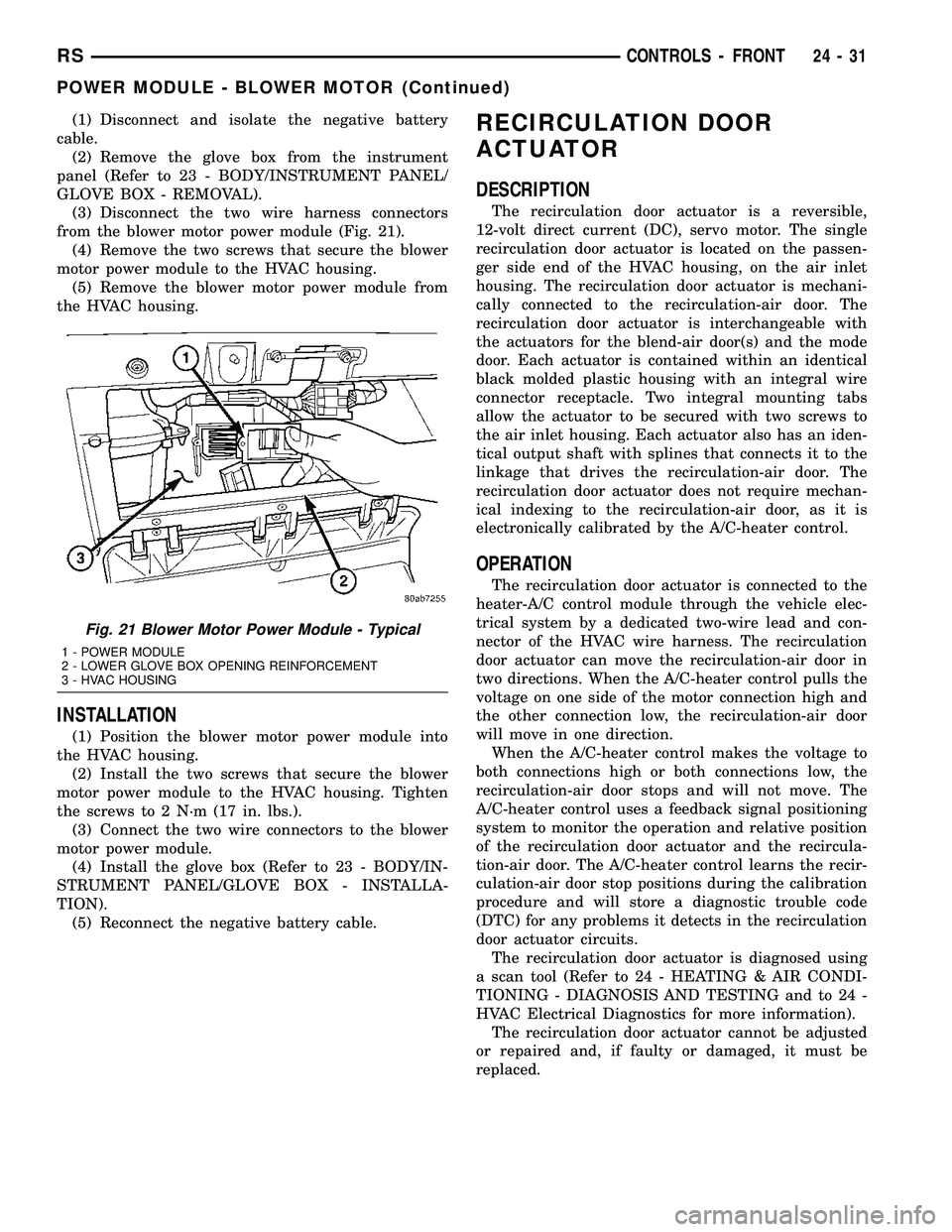
(3) Disconnect the two wire harness connectors
from the blower motor power module (Fig. 21).
(4) Remove the two screws that secure the blower
motor power module to the HVAC housing.
(5) Remove the blower motor power module from
the HVAC housing.
INSTALLATION
(1) Position the blower motor power module into
the HVAC housing.
(2) Install the two screws that secure the blower
motor power module to the HVAC housing. Tighten
the screws to 2 N´m (17 in. lbs.).
(3) Connect the two wire connectors to the blower
motor power module.
(4) Install the glove box (Refer to 23 - BODY/IN-
STRUMENT PANEL/GLOVE BOX - INSTALLA-
TION).
(5) Reconnect the negative battery cable.
RECIRCULATION DOOR
ACTUATOR
DESCRIPTION
The recirculation door actuator is a reversible,
12-volt direct current (DC), servo motor. The single
recirculation door actuator is located on the passen-
ger side end of the HVAC housing, on the air inlet
housing. The recirculation door actuator is mechani-
cally connected to the recirculation-air door. The
recirculation door actuator is interchangeable with
the actuators for the blend-air door(s) and the mode
door. Each actuator is contained within an identical
black molded plastic housing with an integral wire
connector receptacle. Two integral mounting tabs
allow the actuator to be secured with two screws to
the air inlet housing. Each actuator also has an iden-
tical output shaft with splines that connects it to the
linkage that drives the recirculation-air door. The
recirculation door actuator does not require mechan-
ical indexing to the recirculation-air door, as it is
electronically calibrated by the A/C-heater control.
OPERATION
The recirculation door actuator is connected to the
heater-A/C control module through the vehicle elec-
trical system by a dedicated two-wire lead and con-
nector of the HVAC wire harness. The recirculation
door actuator can move the recirculation-air door in
two directions. When the A/C-heater control pulls the
voltage on one side of the motor connection high and
the other connection low, the recirculation-air door
will move in one direction.
When the A/C-heater control makes the voltage to
both connections high or both connections low, the
recirculation-air door stops and will not move. The
A/C-heater control uses a feedback signal positioning
system to monitor the operation and relative position
of the recirculation door actuator and the recircula-
tion-air door. The A/C-heater control learns the recir-
culation-air door stop positions during the calibration
procedure and will store a diagnostic trouble code
(DTC) for any problems it detects in the recirculation
door actuator circuits.
The recirculation door actuator is diagnosed using
a scan tool (Refer to 24 - HEATING & AIR CONDI-
TIONING - DIAGNOSIS AND TESTING and to 24 -
HVAC Electrical Diagnostics for more information).
The recirculation door actuator cannot be adjusted
or repaired and, if faulty or damaged, it must be
replaced.
Fig. 21 Blower Motor Power Module - Typical
1 - POWER MODULE
2 - LOWER GLOVE BOX OPENING REINFORCEMENT
3 - HVAC HOUSING
RSCONTROLS - FRONT24-31
POWER MODULE - BLOWER MOTOR (Continued)
Page 2184 of 2339
CONTROLS - REAR
TABLE OF CONTENTS
page page
A/C-HEATER CONTROL
DESCRIPTION.........................33
OPERATION...........................33
REMOVAL.............................33
INSTALLATION.........................34
BLEND DOOR ACTUATOR
DESCRIPTION.........................34
OPERATION...........................35
REMOVAL.............................35
INSTALLATION.........................35
BLOWER MOTOR RELAY
DESCRIPTION.........................36
OPERATION...........................36
REMOVAL.............................37
INSTALLATION.........................37
BLOWER MOTOR RESISTOR BLOCK
DESCRIPTION.........................37OPERATION...........................37
DIAGNOSIS AND TESTING
REAR BLOWER MOTOR RESISTOR
BLOCK.............................38
REMOVAL.............................38
INSTALLATION.........................39
MODE DOOR ACTUATOR - REAR
DESCRIPTION.........................39
OPERATION...........................39
REMOVAL.............................39
INSTALLATION.........................40
POWER MODULE - REAR BLOWER MOTOR
DESCRIPTION.........................40
OPERATION...........................40
REMOVAL.............................41
INSTALLATION.........................41
A/C-HEATER CONTROL
DESCRIPTION
The rear heating-A/C system is controlled by rota-
ry-type blower motor and temperature controls, cen-
trally mounted directly into the headliner, or if
equipped with the available DVD player, located in
the player housing. The rear A/C-heater control
allows selection of three blower motor speeds and an
Off position when the center knob on the front A/C-
heater control is set to the Rear position, otherwise
the front unit controls both front and rear heater-A/C
operation.
OPERATION
With the rear A/C-heater control active, tempera-
ture selection dictates the air distribution mode (floor
or overhead air) of the rear unit. A cool temperature
setting directs flow to the overhead outlets and a
warm temperature setting to the floor. Refer to Body
Diagnostic Procedures for further diagnostic informa-
tion.
REMOVAL
(1) Disconnect and isolate the negative battery
cable.
(2) If the rear A/C-heater control is mounted in the
headliner, use a trim stick or another suitable wide
flat bladed tool and gently pry the top edge of the
control bezel away from the headliner far enough to
release the two snap clip retainers (Fig. 1).
(3) Pull the rear A/C-heater control and bezel
assembly rearward far enough to access the wire har-
ness connector on the back of the control.
(4) Disconnect the wire harness connector from the
rear A/C-heater control.
(5) Remove the rear A/C-heater control and bezel
assembly from the headliner.
(6) If the rear A/C-heater control is mounted in the
video screen housing, remove the housing from the
headliner (Refer to 8 - ELECTRICAL/AUDIO/VIDEO
SCREEN - REMOVAL).
(7) Remove the three screws that secure the rear
A/C-heater control to the bezel or video screen hous-
ing, depending on application and remove the control
(Fig. 2).
RSCONTROLS - REAR24-33