2005 CHRYSLER VOYAGER warning
[x] Cancel search: warningPage 2267 of 2339
(6) Refill the engine cooling system (Refer to 7 -
COOLING - STANDARD PROCEDURE).
(7) Verify function of the cabin heater.
EXHAUST TUBE
REMOVAL
WARNING: THERE IS A POTENTIAL DANGER OF
SKIN BURNS AS THE SUPPLEMENTAL CABIN
HEATER AND ITS COMPONENTS MAY BE VERY
HOT. MAKE SURE THE CABIN HEATER IS
ALLOWED TO COOL DOWN BEFORE ANY SERVICE
WORK ON THE CABIN HEATER SYSTEM IS
ATTEMPTED.
(1) Raise and support the vehicle. Take note of the
location of the flexible section of the cabin heater
exhaust tube.
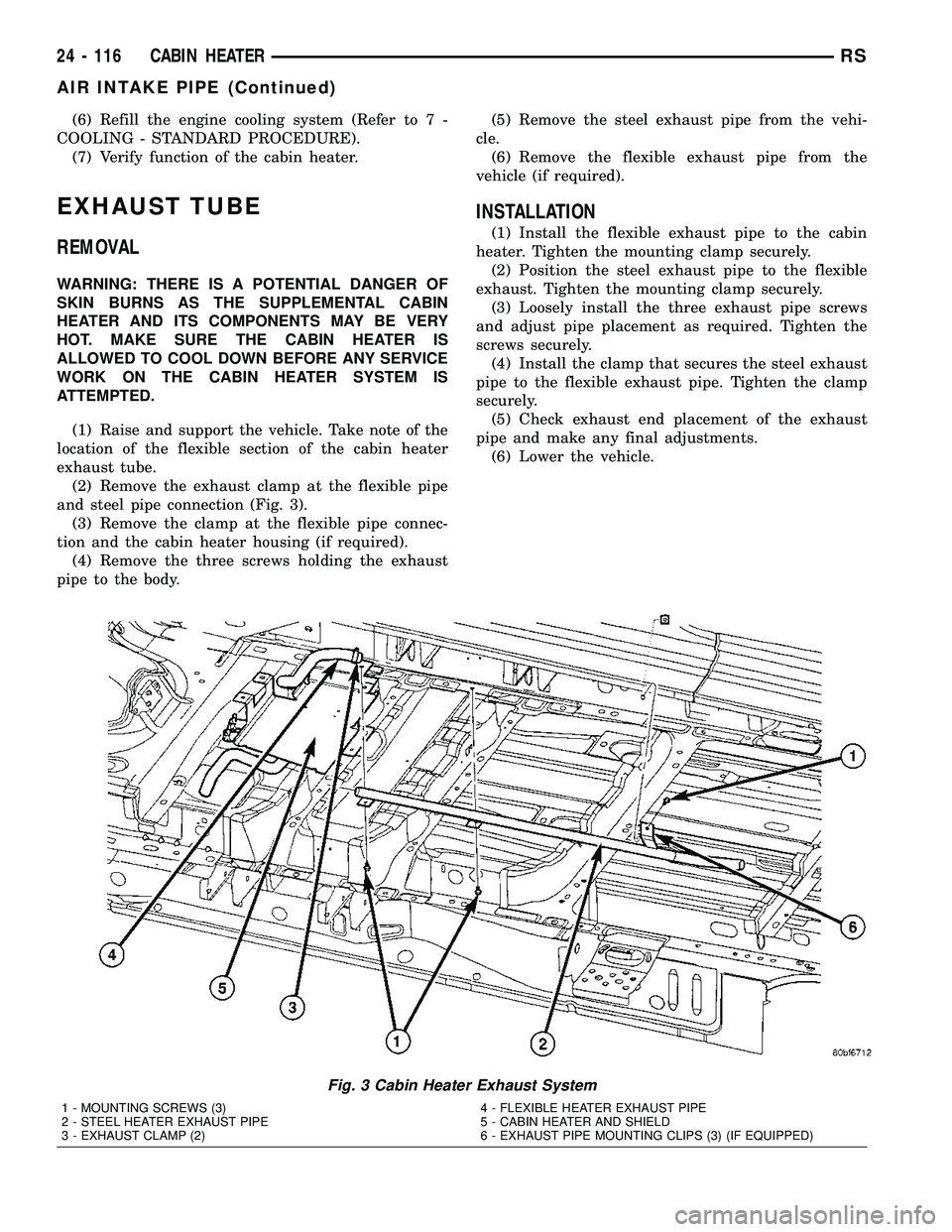
(2) Remove the exhaust clamp at the flexible pipe
and steel pipe connection (Fig. 3).
(3) Remove the clamp at the flexible pipe connec-
tion and the cabin heater housing (if required).
(4) Remove the three screws holding the exhaust
pipe to the body.(5) Remove the steel exhaust pipe from the vehi-
cle.
(6) Remove the flexible exhaust pipe from the
vehicle (if required).
INSTALLATION
(1) Install the flexible exhaust pipe to the cabin
heater. Tighten the mounting clamp securely.
(2) Position the steel exhaust pipe to the flexible
exhaust. Tighten the mounting clamp securely.
(3) Loosely install the three exhaust pipe screws
and adjust pipe placement as required. Tighten the
screws securely.
(4) Install the clamp that secures the steel exhaust
pipe to the flexible exhaust pipe. Tighten the clamp
securely.
(5) Check exhaust end placement of the exhaust
pipe and make any final adjustments.
(6) Lower the vehicle.
Fig. 3 Cabin Heater Exhaust System
1 - MOUNTING SCREWS (3)
2 - STEEL HEATER EXHAUST PIPE
3 - EXHAUST CLAMP (2)4 - FLEXIBLE HEATER EXHAUST PIPE
5 - CABIN HEATER AND SHIELD
6 - EXHAUST PIPE MOUNTING CLIPS (3) (IF EQUIPPED)
24 - 116 CABIN HEATERRS
AIR INTAKE PIPE (Continued)
Page 2269 of 2339
FUEL LINE
STANDARD PROCEDURE
CLEANING
(1) Remove the cabin heater fuel line (Refer to 24 -
HEATING & AIR CONDITIONING/CABIN HEAT-
ER/FUEL LINE - REMOVAL).
(2) With the cabin heater fuel line removed from
the vehicle, place a shop cloth on the fuel tank end of
the fuel line to catch any residue, then apply a small
amount of air pressure to the other end of the fuel
line.
(3) Check to see if air pressure is coming from the
tank end of the line. If pressure is flowing unre-
stricted the line is clean.
(4) If the fuel line shows any signs of being
restricted after air pressure is applied, the fuel line
should be replaced.
(5) Install the cabin heater fuel line (Refer to 24 -
HEATING & AIR CONDITIONING/CABIN HEAT-
ER/FUEL LINE - INSTALLATION).
(6) Verify function of the cabin heater.
REMOVAL
CAUTION: Make sure that the hoist is properly posi-
tioned under the vehicle to prevent damage to the
flexible section of the cabin heater exhaust tube.
(1) Raise and support the vehicle.
NOTE: Utilize an approved fuel storage container to
catch any residual fuel that may drain from the
heater fuel hose or the dosing pump.
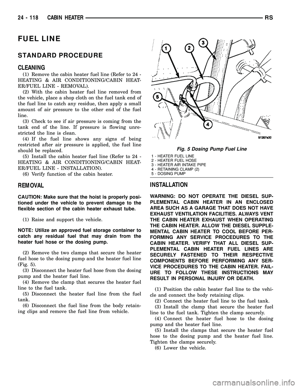
(2) Remove the two clamps that secure the heater
fuel hose to the dosing pump and the heater fuel line
(Fig. 5).
(3) Disconnect the heater fuel hose from the dosing
pump and the heater fuel line.
(4) Remove the clamp that secures the heater fuel
line to the fuel tank.
(5) Disconnect the heater fuel line from the fuel
tank.
(6) Disconnect the fuel line from the body retain-
ing clips and remove the fuel line from vehicle.
INSTALLATION
WARNING: DO NOT OPERATE THE DIESEL SUP-
PLEMENTAL CABIN HEATER IN AN ENCLOSED
AREA SUCH AS A GARAGE THAT DOES NOT HAVE
EXHAUST VENTILATION FACILITIES. ALWAYS VENT
THE CABIN HEATER EXHAUST WHEN OPERATING
THE CABIN HEATER. ALLOW THE DIESEL SUPPLE-
MENTAL CABIN HEATER TO COOL BEFORE PER-
FORMING ANY SERVICE PROCEDURES TO THE
CABIN HEATER. VERIFY THAT ALL DIESEL SUP-
PLEMENTAL CABIN HEATER FUEL LINES ARE
SECURELY FASTENED TO THEIR RESPECTIVE
COMPONENTS BEFORE PERFORMING ANY SER-
VICE PROCEDURES TO THE CABIN HEATER. FAIL-
URE TO FOLLOW THESE INSTRUCTIONS MAY
RESULT IN PERSONAL INJURY OR DEATH.
(1) Position the cabin heater fuel line to the vehi-
cle and connect the body retaining clips.
(2) Connect the heater fuel line to the fuel tank.
(3) Install the clamp that secure the heater fuel
line to the fuel tank. Tighten the clamp securely.
(4) Connect the heater fuel hose to the dosing
pump and the heater fuel line.
(5) Install the clamps that secure the heater fuel
hose to the dosing pump and the heater fuel line.
Tighten the clamps securely.
(6) Lower the vehicle.
Fig. 5 Dosing Pump Fuel Line
1 - HEATER FUEL LINE
2 - HEATER FUEL HOSE
3 - HEATER AIR INTAKE PIPE
4 - RETAINING CLAMP (2)
5 - DOSING PUMP
24 - 118 CABIN HEATERRS
Page 2270 of 2339
NOTE: Verify that there is more than 1/8 of a tank of
fuel in the vehicle's fuel tank before performing this
procedure. Add fuel, if necessary.
NOTE: Failure to prime the dosing pump after drain-
ing the supplemental cabin fuel line will prevent
cabin heater activation during the first attempt to
start the cabin heater. This will also set a diagnostic
trouble code (DTC) in the cabin heater control's
memory. Do not perform the Dosing Pump Priming
procedure if an attempt was made to start the cabin
heater without priming the dosing pump first. This
will put excess fuel in the cabin heater and cause
smoke to emit from the cabin heater exhaust pipe
when cabin heater activation occurs.
(7) Connect the DRBIIItscan tool to the diagnos-
tic link connector.
(8) Turn the ignition to the ON position.
NOTE: Do not activate the dosing pump prime more
than one time. This will put excess fuel in the sup-
plemental cabin heater and cause smoke to emit
from the cabin heater exhaust pipe when cabin
heater activation occurs.
NOTE: A clicking noise heard coming from the dos-
ing pump indicates that the pump is operational.
(9) With the DRBIIItscan tool in Cabin Heater,
select System Tests and Dosing Pump Prime. Allow
the dosing pump to run for the full 45 second cycle
time. When the 45 second cycle is complete, press
Page Back on the DRBIIItscan tool key pad to exit
the Dosing Pump Prime. The Dosing Pump Priming
procedure is now complete.
HEATER HOSES
REMOVAL
(1) Raise and support the vehicle. Take note of the
location of the flexible section of the cabin heater
exhaust tube.
(2) Drain the engine cooling system (Refer to 7 -
COOLING - STANDARD PROCEDURE).
NOTE: Complete removal of the supplemental cabin
heater from vehicle is not required, lowering the
cabin heater allows easier access to coolant line
clamps.(3) Lower the supplemental cabin heater from the
vehicle (Refer to 24 - HEATING & AIR CONDITION-
ING/CABIN HEATER/HEATER UNIT - REMOVAL).
(4) Remove the clamps from both flexible coolant
line ends.
NOTE: It is recommended that both flexible cabin
heater coolant lines be replaced if either cabin
heater coolant line is damaged.
(5) Remove both coolant lines from vehicle.
INSTALLATION
(1) Install both flexible coolant lines to the supple-
mental cabin heater and install the clamps.
(2) Install the flexible coolant lines to the coolant
pipes and install the clamps.
(3) Install the supplemental cabin heater into the
vehicle (Refer to 24 - HEATING & AIR CONDITION-
ING/CABIN HEATER/HEATER UNIT - INSTALLA-
TION).
(4) Lower the vehicle.
(5) Fill the engine cooling system (Refer to 7 -
COOLING - STANDARD PROCEDURE).
(6) Verify operation of the supplemental cabin
heater.
HEATER PIPES
REMOVAL
WARNING: ALLOW THE ENGINE COOLING SYSTEM
TO COOL COMPLETELY BEFORE REMOVING RADI-
ATOR CAP OR DRAINING THE ENGINE COOLING
SYSTEM. PERSONAL INJURY MAY RESULT IF THE
ENGINE COOLING SYSTEM IS OPENED WHILE
ENGINE COOLANT IS HOT AND UNDER PRES-
SURE.
NOTE: Steel heater lines from engine compartment
to the supplemental cabin heater are part of an
assembly that includes the air intake pipe. If the
cabin heater lines or air intake pipe require removal
or replacement the entire cabin heater assembly
will require removal or replacement.
(1) Drain the engine cooling system (Refer to 7 -
COOLING - STANDARD PROCEDURE).
(2) Remove clamps from both the EGR cooler and
the lower heater port. Separate hoses from the mat-
ing plumbing port (Fig. 6).
RSCABIN HEATER24 - 119
FUEL LINE (Continued)
Page 2272 of 2339
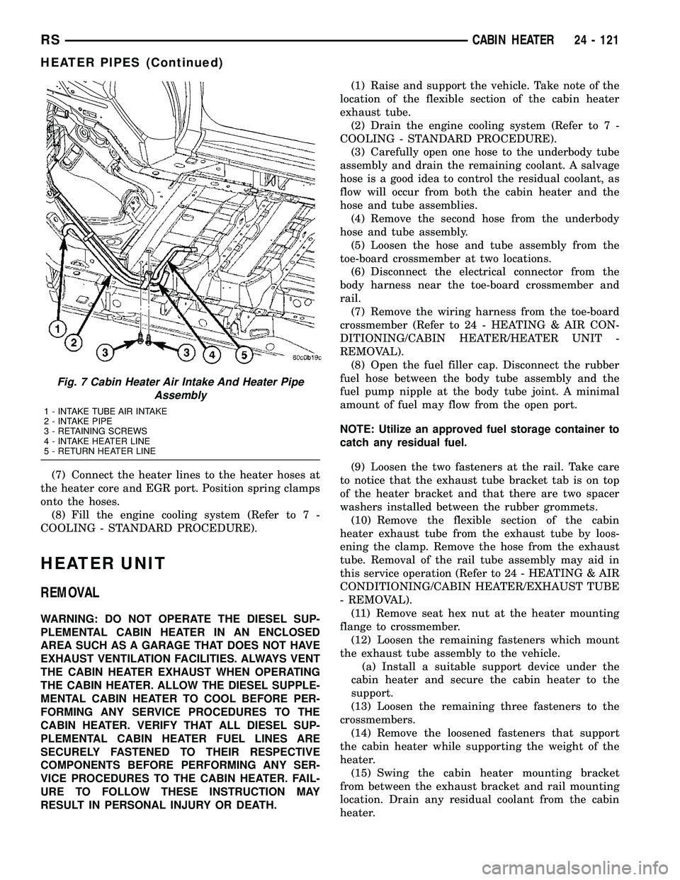
(7) Connect the heater lines to the heater hoses at
the heater core and EGR port. Position spring clamps
onto the hoses.
(8) Fill the engine cooling system (Refer to 7 -
COOLING - STANDARD PROCEDURE).
HEATER UNIT
REMOVAL
WARNING: DO NOT OPERATE THE DIESEL SUP-
PLEMENTAL CABIN HEATER IN AN ENCLOSED
AREA SUCH AS A GARAGE THAT DOES NOT HAVE
EXHAUST VENTILATION FACILITIES. ALWAYS VENT
THE CABIN HEATER EXHAUST WHEN OPERATING
THE CABIN HEATER. ALLOW THE DIESEL SUPPLE-
MENTAL CABIN HEATER TO COOL BEFORE PER-
FORMING ANY SERVICE PROCEDURES TO THE
CABIN HEATER. VERIFY THAT ALL DIESEL SUP-
PLEMENTAL CABIN HEATER FUEL LINES ARE
SECURELY FASTENED TO THEIR RESPECTIVE
COMPONENTS BEFORE PERFORMING ANY SER-
VICE PROCEDURES TO THE CABIN HEATER. FAIL-
URE TO FOLLOW THESE INSTRUCTION MAY
RESULT IN PERSONAL INJURY OR DEATH.(1) Raise and support the vehicle. Take note of the
location of the flexible section of the cabin heater
exhaust tube.
(2) Drain the engine cooling system (Refer to 7 -
COOLING - STANDARD PROCEDURE).
(3) Carefully open one hose to the underbody tube
assembly and drain the remaining coolant. A salvage
hose is a good idea to control the residual coolant, as
flow will occur from both the cabin heater and the
hose and tube assemblies.
(4) Remove the second hose from the underbody
hose and tube assembly.
(5) Loosen the hose and tube assembly from the
toe-board crossmember at two locations.
(6) Disconnect the electrical connector from the
body harness near the toe-board crossmember and
rail.
(7) Remove the wiring harness from the toe-board
crossmember (Refer to 24 - HEATING & AIR CON-
DITIONING/CABIN HEATER/HEATER UNIT -
REMOVAL).
(8) Open the fuel filler cap. Disconnect the rubber
fuel hose between the body tube assembly and the
fuel pump nipple at the body tube joint. A minimal
amount of fuel may flow from the open port.
NOTE: Utilize an approved fuel storage container to
catch any residual fuel.
(9) Loosen the two fasteners at the rail. Take care
to notice that the exhaust tube bracket tab is on top
of the heater bracket and that there are two spacer
washers installed between the rubber grommets.
(10) Remove the flexible section of the cabin
heater exhaust tube from the exhaust tube by loos-
ening the clamp. Remove the hose from the exhaust
tube. Removal of the rail tube assembly may aid in
this service operation (Refer to 24 - HEATING & AIR
CONDITIONING/CABIN HEATER/EXHAUST TUBE
- REMOVAL).
(11) Remove seat hex nut at the heater mounting
flange to crossmember.
(12) Loosen the remaining fasteners which mount
the exhaust tube assembly to the vehicle.
(a) Install a suitable support device under the
cabin heater and secure the cabin heater to the
support.
(13) Loosen the remaining three fasteners to the
crossmembers.
(14) Remove the loosened fasteners that support
the cabin heater while supporting the weight of the
heater.
(15) Swing the cabin heater mounting bracket
from between the exhaust bracket and rail mounting
location. Drain any residual coolant from the cabin
heater.
Fig. 7 Cabin Heater Air Intake And Heater Pipe
Assembly
1 - INTAKE TUBE AIR INTAKE
2 - INTAKE PIPE
3 - RETAINING SCREWS
4 - INTAKE HEATER LINE
5 - RETURN HEATER LINE
RSCABIN HEATER24 - 121
HEATER PIPES (Continued)
Page 2291 of 2339
PCV VALVE
DESCRIPTION
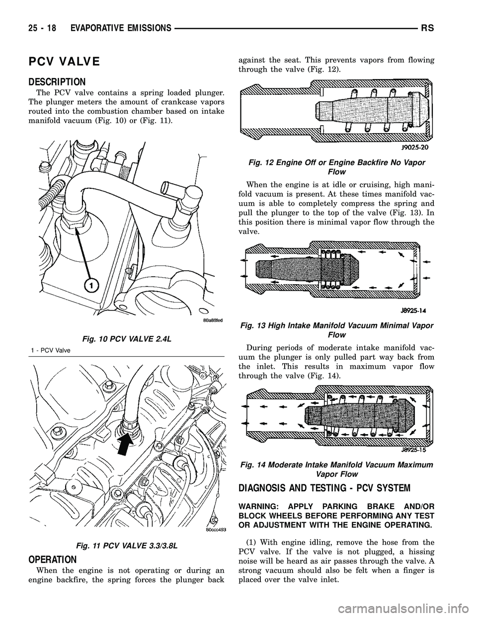
The PCV valve contains a spring loaded plunger.
The plunger meters the amount of crankcase vapors
routed into the combustion chamber based on intake
manifold vacuum (Fig. 10) or (Fig. 11).
OPERATION
When the engine is not operating or during an
engine backfire, the spring forces the plunger backagainst the seat. This prevents vapors from flowing
through the valve (Fig. 12).
When the engine is at idle or cruising, high mani-
fold vacuum is present. At these times manifold vac-
uum is able to completely compress the spring and
pull the plunger to the top of the valve (Fig. 13). In
this position there is minimal vapor flow through the
valve.
During periods of moderate intake manifold vac-
uum the plunger is only pulled part way back from
the inlet. This results in maximum vapor flow
through the valve (Fig. 14).
DIAGNOSIS AND TESTING - PCV SYSTEM
WARNING: APPLY PARKING BRAKE AND/OR
BLOCK WHEELS BEFORE PERFORMING ANY TEST
OR ADJUSTMENT WITH THE ENGINE OPERATING.
(1) With engine idling, remove the hose from the
PCV valve. If the valve is not plugged, a hissing
noise will be heard as air passes through the valve. A
strong vacuum should also be felt when a finger is
placed over the valve inlet.
Fig. 10 PCV VALVE 2.4L
1 - PCV Valve
Fig. 11 PCV VALVE 3.3/3.8L
Fig. 12 Engine Off or Engine Backfire No Vapor
Flow
Fig. 13 High Intake Manifold Vacuum Minimal Vapor
Flow
Fig. 14 Moderate Intake Manifold Vacuum Maximum
Vapor Flow
25 - 18 EVAPORATIVE EMISSIONSRS
Page 2299 of 2339
The Task Manager Screen shows both a Requested
MIL state and an Actual MIL state. When the MIL is
illuminated upon completion of a test for a good trip,
the Requested MIL state changes to OFF. However,
the MIL remains illuminated until the next key
cycle. (On some vehicles, the MIL will actually turn
OFF during the thirdgood trip) During the key cycle
for the third good trip, the Requested MIL state is
OFF, while the Actual MIL state is ON. After the
next key cycle, the MIL is not illuminated and both
MIL states read OFF.
Diagnostic Trouble Codes (DTCs)
With OBD II, different DTC faults have different
priorities according to regulations. As a result, the
priorities determine MIL illumination and DTC era-
sure. DTCs are entered according to individual prior-
ity. DTCs with a higher priority overwrite lower
priority DTCs.
Priorities
²Priority 0 ÐNon-emissions related trouble codes.
²Priority 1 Ð One trip failure of a two trip fault
for non-fuel system and non-misfire. (MIL Off)
²Priority 2 Ð One trip failure of a two trip fault
for fuel system (rich/lean) or misfire. (MIL Off)
²Priority3ÐTwotrip failure for a non-fuel sys-
tem and non-misfire or matured one trip comprehen-
sive component fault. (MIL On)
²Priority4ÐTwotrip failure or matured fault
for fuel system (rich/lean) and misfire or one trip cat-
alyst damaging misfire. Catalyst damage misfire is a
2 trip MIL. The MIL flashes on the first trip when
catalyst damage misfire levels are present. (MIL On)
Non-emissions related failures have no priority.
One trip failures of two trip faults have low priority.
Two trip failures or matured faults have higher pri-
ority. One and two trip failures of fuel system and
misfire monitor take precedence over non-fuel system
and non-misfire failures.
DTC Self Erasure
With one trip components or systems, the MIL is
illuminated upon test failure and DTCs are stored.
Two trip monitors are components requiring failure
in two consecutive trips for MIL illumination. Upon
failure of the first test, the Task Manager enters a
maturing code. If the component fails the test for a
second time the code matures and a DTC is set.
After three good trips the MIL is extinguished and
the Task Manager automatically switches the trip
counter to a warm-up cycle counter. DTCs are auto-
matically erased following 40 warm-up cycles if the
component does not fail again.
For misfire and fuel system monitors, the compo-
nent must pass the test under a Similar Conditions
Window in order to record a good trip. A Similar Con-ditions Window is when engine RPM is within 375
RPM and load is within 20% of when the fault
occurred.
NOTE: It is important to understand that a compo-
nent does not have to fail under a similar window of
operation to mature. It must pass the test under a
Similar Conditions Window when it failed to record
a Good Trip for DTC erasure for misfire and fuel
system monitors.
DTCs can be erased anytime with a scan tool.
Erasing the DTC with the scan tool erases all OBD
II information. The scan tool automatically displays a
warning that erasing the DTC will also erase all
OBD II monitor data. This includes all counter infor-
mation for warm-up cycles, trips and Freeze Frame.
Trip Indicator
TheTripis essential for running monitors and
extinguishing the MIL. In OBD II terms, a trip is a
set of vehicle operating conditions that must be met
for a specific monitor to run. All trips begin with a
key cycle.
Good Trip
The Good Trip counters are as follows:
²Global Good Trip
²Fuel System Good Trip
²Misfire Good Trip
²Alternate Good Trip (appears as a Global Good
Trip on scan tool)
²Comprehensive Components
²Major Monitor
²Warm-Up Cycles
Global Good Trip
To increment a Global Good Trip, the Oxygen sen-
sor and Catalyst efficiency monitors must have run
and passed, and 2 minutes of engine run time.
Fuel System Good Trip
To count a good trip (three required) and turn off
the MIL, the following conditions must occur:
²Engine in closed loop
²Operating in Similar Conditions Window
²Short Term multiplied by Long Term less than
threshold
²Less than threshold for a predetermined time
If all of the previous criteria are met, the PCM will
count a good trip (three required) and turn off the
MIL.
Misfire Good Trip
If the following conditions are met the PCM will
count one good trip (three required) in order to turn
off the MIL:
²Operating in Similar Condition Window
²1000 engine revolutions with no misfire
25 - 26 ON-BOARD DIAGNOSTICSRS
TASK MANAGER (Continued)
Page 2302 of 2339
INDEX
ABS FASTENER TORQUE,SPECIFICATIONS ...................... 5-91
ABSORBER - DESCRIPTION, SHOCK .......2-36
ABSORBER - INSTALLATION, SHOCK ......2-38
ABSORBER - OPERATION, SHOCK ........2-36
ABSORBER - REMOVAL, SHOCK ..........2-36
ABSORBER (UPPER BUSHING) - ASSEMBLY, SHOCK .................... 2-37
ABSORBER (UPPER BUSHING) - DISASSEMBLY, SHOCK .................2-37
A/C CLUTCH BREAK-IN, STANDARD PROCEDURE ........................ 24-15
A/C COMPRESSOR CLUTCH COIL, DIAGNOSIS AND TESTING .............24-14
A/C COMPRESSOR CLUTCH RELAY - DESCRIPTION ....................... 24-18
A/C COMPRESSOR CLUTCH RELAY - INSTALLATION ....................... 24-19
A/C COMPRESSOR CLUTCH RELAY - OPERATION ......................... 24-18
A/C COMPRESSOR CLUTCH RELAY - REMOVAL .......................... 24-19
A/C COMPRESSOR CLUTCH/COIL - DESCRIPTION ....................... 24-13
A/C COMPRESSOR CLUTCH/COIL - OPERATION ......................... 24-13
A/C COMPRESSOR, DESCRIPTION .......24-72
A/C COMPRESSOR, INSTALLATION .......24-74
A/C COMPRESSOR MOUNTING BRACKET, 2.4L ENGINE ...........24-74,24-75
A/C COMPRESSOR NOISE DIAGNOSIS, DIAGNOSIS AND TESTING .............24-72
A/C COMPRESSOR, OPERATION .........24-72
A/C COMPRESSOR, REMOVAL ..........24-73
A/C CONDENSER - DESCRIPTION ........24-75
A/C CONDENSER - OPERATION ..........24-75
A/C COOL DOWN TEST, DIAGNOSIS AND TESTING ............................ 24-6
A/C DISCHARGE LINE - INSTALLATION . . . 24-80
A/C DISCHARGE LINE - REMOVAL .......24-79
A/C EVAPORATOR - DESCRIPTION . . 24-80,24-98
A/C EVAPORATOR - INSTALLATION ......24-81
A/C EVAPORATOR - OPERATION ....24-80,24-98
A/C EVAPORATOR - REMOVAL ..........24-81
A/C EVAPORATOR, INSTALLATION - REAR ............................. 24-100
A/C EVAPORATOR LINE EXTENSION, INSTALLATION - REAR ...............24-100
A/C EVAPORATOR LINE EXTENSION, REMOVAL - REAR .................... 24-99
A/C EVAPORATOR, REMOVAL - REAR .....24-98
A/C EXPANSION VALVE - DESCRIPTION . . 24-100
A/C EXPANSION VALVE - OPERATION ....24-100
A/C EXPANSION VALVE, DIAGNOSIS AND TESTING - FRONT .................... 24-82
A/C EXPANSION VALVE, DIAGNOSIS AND TESTING - REAR .................... 24-101
A/C HEATER CONTROL - DESCRIPTION . . . 24-19
A/C PERFORMANCE TEST, DIAGNOSIS AND TESTING ........................ 24-7
A/C PRESSURE TRANSDUCER - DESCRIPTION ....................... 24-20
A/C PRESSURE TRANSDUCER - OPERATION ......................... 24-20
A/C PRESSURE TRANSDUCER, DIAGNOSIS AND TESTING .............24-21
A/C SYSTEM - CAUTION ...............24-66
A/C SYSTEM, SPECIFICATIONS ..........24-11
A/C SYSTEM, WARNING ...............24-66
ACCELERATOR PEDAL - INSTALLATION . . . 14-28
ACCELERATOR PEDAL - REMOVAL .......14-28
ACCESSORY DRIVE BELT - DIAGNOSIS AND TESTING .........................7-7
ACCESSORY DRIVE BELT TENSION, SPECIFICATIONS .......................7-5
ACCUMULATOR - DESCRIPTION . . . 21-218,21-73
ACCUMULATOR - OPERATION ....21-218,21-73
A/C-HEATER CONTROL - DESCRIPTION . . . 24-33
A/C-HEATER CONTROL - INSTALLATION . . . 24-34
A/C-HEATER CONTROL - OPERATION .....24-33
A/C-HEATER CONTROL - REMOVAL ......24-33
A/C-HEATER CONTROL CALIBRATION, STANDARD PROCEDURE ...............24-19
ACTUATOR - DESCRIPTION, BLEND DOOR ........................ 24-22,24-34
ACTUATOR - DESCRIPTION, ENGAGE ......8N-9
ACTUATOR - DESCRIPTION, LATCH ......8N-13 ACTUATOR - DESCRIPTION, MODE
DOOR ............................. 24-29
ACTUATOR - DESCRIPTION, RECIRCULATION DOOR ................24-31
ACTUATOR - INSTALLATION, BLEND DOOR ........................ 24-22,24-35
ACTUATOR - INSTALLATION, ENGAGE ....8N-10
ACTUATOR - INSTALLATION, INSIDE HANDLE ............................ 23-27
ACTUATOR - INSTALLATION, LATCH .....8N-14
ACTUATOR - INSTALLATION, MODE DOOR ............................. 24-30
ACTUATOR - INSTALLATION, RECIRCULATION DOOR ................24-32
ACTUATOR - OPERATION, BLEND DOOR . . 24-22, 24-35
ACTUATOR - OPERATION, ENGAGE .......8N-9
ACTUATOR - OPERATION, LATCH ........8N-13
ACTUATOR - OPERATION, MODE DOOR . . . 24-29
ACTUATOR - OPERATION, RECIRCULATION DOOR ................24-31
ACTUATOR - REAR - DESCRIPTION, MODE DOOR ........................ 24-39
ACTUATOR - REAR - INSTALLATION, MODE DOOR ........................ 24-40
ACTUATOR - REAR - OPERATION, MODE DOOR ............................. 24-39
ACTUATOR - REAR - REMOVAL, MODE DOOR ............................. 24-39
ACTUATOR - REMOVAL, BLEND DOOR . . . 24-22, 24-35
ACTUATOR - REMOVAL, ENGAGE ..........8N-9
ACTUATOR - REMOVAL, INSIDE HANDLE . . 23-27
ACTUATOR - REMOVAL, LATCH .........8N-13
ACTUATOR - REMOVAL, MODE DOOR ....24-29
ACTUATOR - REMOVAL, RECIRCULATION DOOR ............................. 24-32
ADAPTER - INSTALLATION, FRONT DISC BRAKE CALIPER ...................... 5-31
ADAPTER - INSTALLATION, OIL FILTER . . . 9-142
ADAPTER - REMOVAL, FRONT DISC BRAKE CALIPER ...................... 5-31
ADAPTER - REMOVAL, OIL FILTER .......9-142
ADAPTIVE MEMORIES, OPERATION - FUEL CORRECTION OR ................14-24
ADDING ADDITIONAL COOLANT - STANDARD PROCEDURE .................7-4
ADDITIONAL COOLANT - STANDARD PROCEDURE, ADDING ...................7-4
ADHESIVE ATTACHED - INSTALLATION, EXTERIOR NAME PLATES ..............23-51
ADHESIVE ATTACHED - REMOVAL, EXTERIOR NAME PLATES ..............23-51
ADHESIVE LOCATIONS - FOLD-IN-FLOOR ONLY - SPECIFICATIONS,
STRUCTURAL ...................... 23-228
ADHESIVE LOCATIONS - SPECIFICATIONS, STRUCTURAL ........23-218
ADJUSTABLE - INSTALLATION, PEDALS ....5-43
ADJUSTABLE - REMOVAL, PEDALS .......5-40
ADJUSTABLE PEDALS SWITCH - INSTALLATION ........................ 5-11
ADJUSTABLE PEDALS SWITCH - REMOVAL ........................... 5-11
ADJUSTE R-BOR C-PILLAR -
INSTALLATION, SEAT BELT HEIGHT ......8O-38
ADJUSTE R-BOR C-PILLAR -
REMOVAL, SEAT BELT HEIGHT ..........8O-38
ADJUSTER - DIAGNOSIS AND TESTING, DRUM BRAKE AUTOMATIC ..............5-14
ADJUSTER - INSTALLATION, FRONT SEAT TRACK MANUAL ...............23-126
ADJUSTER - INSTALLATION, FRONT SEAT TRACK POWER ................23-124
ADJUSTER - REMOVAL, FRONT SEAT TRACK MANUAL .................... 23-125
ADJUSTER - REMOVAL, FRONT SEAT TRACK POWER ..................... 23-124
ADJUSTER KNOB - INSTALLATION, SEAT BELT HEIGHT ....................... 8O-38
ADJUSTER KNOB - REMOVAL, SEAT BELT HEIGHT ....................... 8O-38
ADJUSTER NOISE DIAGNOSIS - DIAGNOSIS AND TESTING, HYDRAULIC
LASH ............................... 9-34
ADJUSTER TENSION RELEASE - STANDARD PROCEDURE, PARKING
BRAKE AUTOMATIC .................... 5-63ADJUSTER TENSION RESET -
STANDARD PROCEDURE, PARKING
BRAKE AUTOMATIC .................... 5-64
ADJUSTER/MANUAL - OCS - INSTALLATION, FRONT SEAT TRACK ....23-128
ADJUSTER/MANUAL - OCS - REMOVAL, FRONT SEAT TRACK .................23-126
ADJUSTER/POWER - OCS - INSTALLATION, FRONT SEAT TRACK ....23-125
ADJUSTER/POWER - OCS - REMOVAL, FRONT SEAT TRACK .................23-124
ADJUSTERS - INSTALLATION, HYDRAULIC LASH ..................... 9-35
ADJUSTERS - REMOVAL, HYDRAULIC LASH ............................... 9-35
AERATION - DIAGNOSIS AND TESTING, COOLING SYSTEM .....................7-4
AFTER AN AIRBAG DEPLOYMENT - STANDARD PROCEDURE, SERVICE .......8O-7
AIR CLEANER ELEMENT - INSTALLATION . 9-101, 9-24
AIR CLEANER ELEMENT - REMOVAL . 9-101,9-24
AIR CLEANER HOUSING - INSTALLATION . 9-102, 9-25
AIR CLEANER HOUSING - REMOVAL . 9-101,9-25
AIR CONDITIONER, DESCRIPTION - HEATER ............................. 24-1
AIR CONDITIONER, OPERATION - HEATER ............................. 24-4
AIR CONTROL MOTOR - DESCRIPTION, IDLE ............................... 14-33
AIR CONTROL MOTOR - INSTALLATION, IDLE ............................... 14-33
AIR CONTROL MOTOR - OPERATION, IDLE ............................... 14-33
AIR CONTROL MOTOR - REMOVAL, IDLE . . 14-33
AIR EXHAUSTER - DESCRIPTION, REAR QUARTER PANEL/FENDER ..............23-59
AIR EXHAUSTER - INSTALLATION, REAR QUARTER PANEL/FENDER ..............23-60
AIR EXHAUSTER - REMOVAL, REAR QUARTER PANEL/FENDER ..............23-59
AIR FILTER - DESCRIPTION ............24-42
AIR FILTER - INSTALLATION ............24-43
AIR FILTER - REMOVAL ...............24-42
AIR GAP, SPECIFICATIONS - WHEEL SPEED SENSOR ....................... 5-91
AIR INTAKE PIPE - INSTALLATION ......24-115
AIR INTAKE PIPE - REMOVAL ..........24-115
AIR OUTLETS - DESCRIPTION .....24-43,24-56
AIR OUTLETS - INSTALLATION ..........24-56
AIR OUTLETS - REMOVAL .............24-56
AIR PRESSURE TESTS - DIAGNOSIS AND TESTING, CLUTCH ...........21-153,21-8
AIR TEMPERATURE SENSOR - DESCRIPTION, INLET .................14-34
AIRBAG - DESCRIPTION, CURTAIN .......8O-12
AIRBAG - DESCRIPTION, DRIVER ........8O-16
AIRBAG - DESCRIPTION, KNEE BLOCKER . 8O-22
AIRBAG - DESCRIPTION, PASSENGER ....8O-30
AIRBAG - INSTALLATION, CURTAIN ......8O-16
AIRBAG - INSTALLATION, DRIVER .......8O-18
AIRBAG - INSTALLATION, KNEE BLOCKER .......................... 8O-23
AIRBAG - INSTALLATION, PASSENGER . . . 8O-32
AIRBAG - OPERATION, CURTAIN ........8O-13
AIRBAG - OPERATION, DRIVER .........8O-16
AIRBAG - OPERATION, KNEE BLOCKER . . . 8O-22
AIRBAG - OPERATION, PASSENGER ......8O-30
AIRBAG - REMOVAL, CURTAIN ..........8O-14
AIRBAG - REMOVAL, DRIVER ...........8O-17
AIRBAG - REMOVAL, KNEE BLOCKER ....8O-23
AIRBAG - REMOVAL, PASSENGER .......8O-30
AIRBAG DEPLOYMENT - STANDARD PROCEDURE, SERVICE AFTER AN ........8O-7
AIRBAG DISABLED INDICATOR - DESCRIPTION, PASSENGER ............8O-33
AIRBAG DISABLED INDICATOR - INSTALLATION, PASSENGER ...........8O-34
AIRBAG DISABLED INDICATOR - OPERATION, PASSENGER ..............8O-33
AIRBAG DISABLED INDICATOR - REMOVAL, PASSENGER ...............8O-34
AIRBAG SYSTEM - DIAGNOSIS AND TESTING ............................ 8O-6
AIRBAGS - STANDARD PROCEDURE, HANDLING .......................... 8O-6
RS INDEX1
Description Group-Page Description Group-Page Description Group-Page
Page 2307 of 2339
CABLE END CLEANING ANDLUBRICATION - STANDARD
PROCEDURE ......................... 5-65
CABLE RESISTANCE, SPECIFICATIONS - SPARK PLUG ......................... 8I-2
CABLES - ADJUSTMENT, PARKING BRAKE .............................. 5-65
CABLES - DESCRIPTION, BATTERY .......8F-16
CABLES - OPERATION, BATTERY ........8F-17
CABLES, DIAGNOSIS AND TESTING - BATTERY ........................... 8F-17
CALIBRATION, STANDARD PROCEDURE - A/C-HEATER CONTROL ................24-19
CALIBRATION, STANDARD PROCEDURE - COMPASS ........................... 8M-4
CALIPER - CLEANING ..............5-25,5-29
CALIPER - INSPECTION ............5-25,5-29
CALIPER - INSTALLATION, REAR DISC BRAKE .............................. 5-30
CALIPER - REMOVAL, REAR DISC BRAKE .............................. 5-28
CALIPER ADAPTER - INSTALLATION, FRONT DISC BRAKE ................... 5-31
CALIPER ADAPTER - REMOVAL, FRONT DISC BRAKE ......................... 5-31
CALIPER (CONTINENTAL TEVES BRAKES) - INSTALLATION, FRONT
DISC BRAKE ......................... 5-27
CALIPER (CONTINENTAL TEVES BRAKES) - REMOVAL, FRONT DISC
BRAKE .............................. 5-24
CALIPER GUIDE PIN BUSHINGS (CONTINENTAL TEVES BRAKES) -
ASSEMBLY ............................ 5-25
CALIPER GUIDE PIN BUSHINGS (CONTINENTAL TEVES BRAKES) -
DISASSEMBLY ........................ 5-24
CALIPER GUIDE PINS (TRW BRAKES) - INSTALLATION, DISC BRAKE ............5-32
CALIPER GUIDE PINS (TRW BRAKES) - REMOVAL, DISC BRAKE ................5-31
CALIPER PISTON AND SEAL - ASSEMBLY ...................... 5-26,5-30
CALIPER PISTON AND SEAL - DISASSEMBLY .................... 5-24,5-28
CALIPER (TRW BRAKES) - INSTALLATION, FRONT DISC BRAKE ......5-27
CALIPER (TRW BRAKES) - REMOVAL, FRONT DISC BRAKE ................... 5-24
CAMSHAFT & BEARINGS (IN BLOCK) - DESCRIPTION ....................... 9-118
CAMSHAFT & BEARINGS (IN BLOCK) - INSPECTION ........................ 9-118
CAMSHAFT & BEARINGS (IN BLOCK) - INSTALLATION ....................... 9-118
CAMSHAFT & BEARINGS (IN BLOCK) - OPERATION ......................... 9-118
CAMSHAFT & BEARINGS (IN BLOCK) - REMOVAL .......................... 9-118
CAMSHAFT END PLAY - STANDARD PROCEDURE, MEASURING ..............9-29
CAMSHAFT OIL SEAL(S) - INSTALLATION . . 9-29
CAMSHAFT OIL SEAL(S) - REMOVAL ......9-28
CAMSHAFT POSITION SENSOR - DESCRIPTION ......................... 8I-4
CAMSHAFT POSITION SENSOR - OPERATION .......................... 8I-4
CAMSHAFT SPROCKET - INSTALLATION, TIMING CHAIN ....................... 9-160
CAMSHAFT SPROCKET - REMOVAL, TIMING CHAIN ....................... 9-159
CAMSHAFT SPROCKETS - INSTALLATION . . 9-67
CAMSHAFT SPROCKETS - REMOVAL ......9-66
CAMSHAFT(S) - CLEANING ..............9-30
CAMSHAFT(S) - DESCRIPTION ...........9-29
CAMSHAFT(S) - INSPECTION ............9-30
CAMSHAFT(S) - INSTALLATION ..........9-31
CAMSHAFT(S) - OPERATION .............9-29
CAMSHAFT(S) - REMOVAL ..............9-30
CANISTER - DESCRIPTION, VAPOR ......25-19
CANISTER - INSTALLATION, REAR EVAP . . 25-21
CANISTER - OPERATION, VAPOR ........25-19
CANISTER - REMOVAL, REAR EVAP ......25-20
CAP - DESCRIPTION, FUEL FILLER .......25-13
CAP - DESCRIPTION, RADIATOR PRESSURE .......................... 7-27
CAP - INSTALLATION, INSTRUMENT PANEL RIGHT END ................... 23-72CAP - OPERATION, FUEL FILLER
........25-13
CAP - OPERATION, RADIATOR PRESSURE .......................... 7-27
CAP - REMOVAL, INSTRUMENT PANEL RIGHT END ......................... 23-72
CAP TESTING - DIAGNOSIS AND TESTING, COOLING SYSTEM
PRESSURE .......................... 7-28
CAP TO FILLER NECK SEAL - DIAGNOSIS AND TESTING, RADIATOR .....7-28
CAPACITIES - SPECIFICATIONS, FLUID ......0-6
CARE, CLEANING - WHEEL AND WHEEL TRIM .............................. 22-19
CARGO - INSTALLATION, AWD, HEAVY DUTY ............................... 2-36
CARGO - INSTALLATION, SPRING ........2-40
CARGO - REMOVAL, AWD, HEAVY DUTY . . . 2-36
CARGO - REMOVAL, SPRING ............2-40
CARPET INSERT - FOLD-IN-FLOOR - INSTALLATION, SECOND ROW FLOOR
TUB ............................... 23-98
CARPET INSERT - FOLD-IN-FLOOR - REMOVAL, SECOND ROW FLOOR TUB ....23-98
CARPET TRIM RING AND COVER - FOLD-IN-FLOOR - INSTALLATION ........23-84
CARPET TRIM RING AND COVER - FOLD-IN-FLOOR - REMOVAL ............23-84
CARPETS - FOLD-IN-FLOOR - INSTALLATION ....................... 23-83
CARPETS - FOLD-IN-FLOOR - REMOVAL . . 23-82
CARPETS AND FLOOR MATS - INSTALLATION ....................... 23-81
CARPETS AND FLOOR MATS - REMOVAL . 23-81
CARPETS INSERT - FOLD-IN-FLOOR - INSTALLATION, REAR FLOOR TUB .......23-96
CARPETS INSERT - FOLD-IN-FLOOR - REMOVAL, REAR FLOOR TUB ...........23-95
CARRIER ASSEMBLY - DESCRIPTION, BALANCE SHAFTS ..................... 9-71
CARRIER ASSEMBLY - INSTALLATION, BALANCE SHAFTS ..................... 9-73
CARRIER ASSEMBLY - OPERATION, BALANCE SHAFTS ..................... 9-71
CARRIER ASSEMBLY - REMOVAL, BALANCE SHAFTS ..................... 9-71
CATALYTIC CONVERTER - DESCRIPTION . . . 11-4
CATALYTIC CONVERTER - INSPECTION ....11-6
CATALYTIC CONVERTER - INSTALLATION . . . 11-6
CATALYTIC CONVERTER - OPERATION .....11-4
CATALYTIC CONVERTER - REMOVAL ......11-5
CAUTION, A/C SYSTEM ................24-66
CAUTION, DESCRIPTION .................5-4
CAUTION, DESCRIPTION ...............19-37
CAUTION, OPERATION .................5-90
CAUTION, SENSOR - TPM ..............22-11
CAUTIONS, WARNING - WARNINGS . 19-10,19-26
CD CHANGER - DESCRIPTION ..........8A-11
CD CHANGER - INSTALLATION ..........8A-11
CD CHANGER - OPERATION ............8A-11
CD CHANGER - REMOVAL .............8A-11
CENTER - DESCRIPTION, ELECTRONIC VEHICLE INFO ....................... 8M-7
CENTER - INSTALLATION, MESSAGE ......8M-1
CENTER - OPERATION, ELECTRONIC VEHICLE INFO ....................... 8M-7
CENTER - REMOVAL, MESSAGE .........8M-1
CENTER BEZEL - INSTALLATION, INSTRUMENT PANEL .................. 23-72
CENTER BEZEL - REMOVAL, INSTRUMENT PANEL .................. 23-71
CENTER BEZEL OUTLETS, INSTALLATION - FRONT ............................ 24-45
CENTER BEZEL OUTLETS, REMOVAL - FRONT ............................. 24-44
CENTER CONSOLE LAMP - INSTALLATION ....................... 8L-21
CENTER CONSOLE LAMP - REMOVAL ....8L-21
CENTER CONSOLE LAMP SWITCH - INSTALLATION ....................... 8L-21
CENTER CONSOLE LAMP SWITCH - REMOVAL .......................... 8L-21
CENTER, DIAGNOSIS AND TESTING - ELECTRONIC VEHICLE INFORMATION .....8M-8
CENTER HIGH MOUNTED STOP LAMP - INSTALLATION ........................ 8L-6
CENTER HIGH MOUNTED STOP LAMP - REMOVAL ........................... 8L-6CENTER HIGH MOUNTED STOP LAMP
UNIT - INSTALLATION .................. 8L-6
CENTER HIGH MOUNTED STOP LAMP UNIT - REMOVAL ..................... 8L-6
CENTER HINGE - INSTALLATION .........23-24
CENTER HINGE - REMOVAL ............23-24
CENTER LAP BELT - FOLD-IN-FLOOR - INSTALLATION, SEAT BELT ............23-157
CENTER LAP BELT - FOLD-IN-FLOOR - REMOVAL, SEAT BELT ................23-157
CENTER PROGRAMMING, STANDARD PROCEDURE - ELECTRONIC VEHICLE
INFORMATION ....................... 8M-8
CENTER STRIKER - INSTALLATION .......23-28
CENTER STRIKER - REMOVAL ..........23-28
CENTERING - STANDARD PROCEDURE, CLOCKSPRING ...................... 8O-11
CHAIN AND CAMSHAFT SPROCKET - INSTALLATION, TIMING ................9-160
CHAIN AND CAMSHAFT SPROCKET - REMOVAL, TIMING ................... 9-159
CHAIN COVER - INSTALLATION, TIMING . . 9-157
CHAIN COVER - REMOVAL, TIMING ......9-156
CHAIN WEAR - STANDARD PROCEDURE, MEASURING TIMING .................. 9-155
CHANGE - STANDARD PROCEDURE, ENGINE OIL AND FILTER ...........9-139,9-54
CHANGER - DESCRIPTION, CD ..........8A-11
CHANGER - INSTALLATION, CD .........8A-11
CHANGER - OPERATION, CD ............8A-11
CHANGER - REMOVAL, CD ..............8A-11
CHANNEL - INSTALLATION, WATER .....23-174
CHANNEL - REMOVAL, WATER .........23-174
CHARGE LEVEL TEST, DIAGNOSIS AND TESTING - SYSTEM ................... 24-67
CHARGE, STANDARD PROCEDURE - REFRIGERANT SYSTEM ...............24-71
CHARGING, STANDARD PROCEDURE - CONVENTIONAL BATTERY ..............8F-11
CHARGING, STANDARD PROCEDURE - SPIRAL PLATE BATTERY ...............8F-10
CHARGING SYSTEM - DESCRIPTION .....8F-21
CHARGING SYSTEM - OPERATION .......8F-21
CHARTS - DIAGNOSIS AND TESTING, STEERING SYSTEM DIAGNOSIS ..........19-3
CHARTS - SPECIFICATIONS, COLOR CODE ............................. 23-100
CHECK - DIAGNOSIS AND TESTING, COOLING SYSTEM FLOW ................7-3
CHECK - DIAGNOSIS AND TESTING, EXHAUST SYSTEM RESTRICTION .........11-2
CHECK - STANDARD PROCEDURE, COOLANT LEVEL .......................7-4
CHECK - STANDARD PROCEDURE, ENGINE OIL LEVEL ................... 9-140
CHECK, STANDARD PROCEDURE - ENGINE OIL LEVEL .................... 9-54
CHECK, STANDARD PROCEDURE - FLUID LEVEL AND CONDITION .........21-230,21-82
CHECK STRAP - INSTALLATION .........23-15
CHECK STRAP - REMOVAL .............23-15
CHECKING - STANDARD PROCEDURE, BRAKE FLUID LEVEL ................... 5-33
CHECKING - STANDARD PROCEDURE, POWER STEERING FLUID LEVEL ........19-44
CHECKING BATTERY ELECTROLYTE LEVEL, STANDARD PROCEDURE .........8F-14
CHECKING ENGINE OIL PRESSURE - DIAGNOSIS AND TESTING ..............9-53
CHECKING POWER STEERING BELT TENSION - STANDARD PROCEDURE .......7-8
CHILD RESTRAINT ANCHOR - DESCRIPTION ........................ 8O-9
CHILD RESTRAINT ANCHOR - OPERATION ......................... 8O-10
CHILD SEAT - INSTALLATION, QUAD ....23-106
CHILD SEAT - REMOVAL, QUAD ........23-106
CHILD SEAT MODULE, BENCH SEAT - REMOVAL ......................... 23-104
CHIME SYSTEM - DIAGNOSIS AND TESTING ............................ 8B-2
CHIME/BUZZER - DESCRIPTION ..........8B-1
CHIME/BUZZER - OPERATION ............8B-1
CHIME/BUZZER - WARNING .............8B-2
CHIME/THERMISTOR - DESCRIPTION .....8N-8
CHIME/THERMISTOR - INSTALLATION .....8N-9
CHIME/THERMISTOR - OPERATION .......8N-8
CHIME/THERMISTOR - REMOVAL ........8N-8
6 INDEXRS
Description Group-Page Description Group-Page Description Group-Page