Page 1472 of 2339

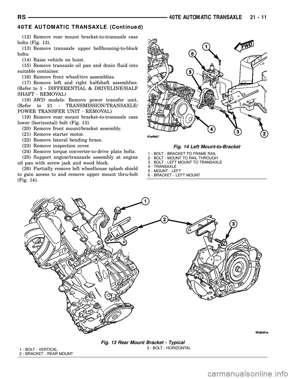
(12) Remove rear mount bracket-to-transaxle case
bolts (Fig. 13).
(13) Remove transaxle upper bellhousing-to-block
bolts.
(14) Raise vehicle on hoist.
(15) Remove transaxle oil pan and drain fluid into
suitable container.
(16) Remove front wheel/tire assemblies.
(17) Remove left and right halfshaft assemblies.
(Refer to 3 - DIFFERENTIAL & DRIVELINE/HALF
SHAFT - REMOVAL)
(18) AWD models: Remove power transfer unit.
(Refer to 21 - TRANSMISSION/TRANSAXLE/
POWER TRANSFER UNIT - REMOVAL)
(19) Remove rear mount bracket-to-transaxle case
lower (horizontal) bolt (Fig. 13).
(20) Remove front mount/bracket assembly.
(21) Remove starter motor.
(22) Remove lateral bending brace.
(23) Remove inspection cover.
(24) Remove torque converter-to-drive plate bolts.
(25) Support engine/transaxle assembly at engine
oil pan with screw jack and wood block.
(26) Partially remove left wheelhouse splash shield
to gain access to and remove upper mount thru-bolt
(Fig. 14).
Fig. 13 Rear Mount Bracket - Typical
1 - BOLT - VERTICAL
2 - BRACKET - REAR MOUNT3 - BOLT - HORIZONTAL
Fig. 14 Left Mount-to-Bracket
1 - BOLT - BRACKET TO FRAME RAIL
2 - BOLT - MOUNT TO RAIL THROUGH
3 - BOLT - LEFT MOUNT TO TRANSAXLE
4 - TRANSAXLE
5 - MOUNT - LEFT
6 - BRACKET - LEFT MOUNT
RS40TE AUTOMATIC TRANSAXLE21-11
40TE AUTOMATIC TRANSAXLE (Continued)
Page 1473 of 2339

(27) Lower engine/transaxle assembly with screw
jack.
(28) Obtain helper and/or transmission jack.
Secure transmission jack to transaxle assembly.
(29) Remove upper mount bracket from transaxle
(Fig. 14).
(30) Remove remaining transaxle bellhousing-to-
engine bolts.
(31) Remove transaxle assembly from vehicle.
DISASSEMBLY
NOTE: If transaxle is being overhauled (clutch
and/or seal replacement) or replaced, it is neces-
sary to perform the PCM/TCM Quick Learn Proce-
dure. (Refer to 8 - ELECTRICAL/ELECTRONIC
CONTROL MODULES/POWERTRAIN/TRANSMIS-
SION CONTROL MODULE - STANDARD PROCE-
DURE)
NOTE: This procedure does not include final drive
(differential) disassembly.
(1) Remove input and output speed sensors.
(2) Remove three (3) solenoid/pressure switch
assembly-to-case bolts.
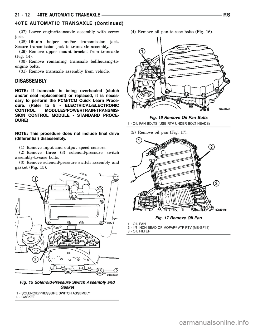
(3) Remove solenoid/pressure switch assembly and
gasket (Fig. 15).(4) Remove oil pan-to-case bolts (Fig. 16).
(5) Remove oil pan (Fig. 17).
Fig. 15 Solenoid/Pressure Switch Assembly and
Gasket
1 - SOLENOID/PRESSURE SWITCH ASSEMBLY
2 - GASKET
Fig. 16 Remove Oil Pan Bolts
1 - OIL PAN BOLTS (USE RTV UNDER BOLT HEADS)
Fig. 17 Remove Oil Pan
1 - OIL PAN
2 - 1/8 INCH BEAD OF MOPARTATF RTV (MS-GF41)
3 - OIL FILTER
21 - 12 40TE AUTOMATIC TRANSAXLERS
40TE AUTOMATIC TRANSAXLE (Continued)
Page 1474 of 2339
(6) Remove oil filter (Fig. 18).
(7) Turn manual valve fully clock-wise to get park
rod into position for removal.
(8) Remove valve body-to-case bolts (Fig. 19).
CAUTION: Do not handle the valve body assembly
from the manual valve. Damage can result.(9) Using a screwdriver, push park rod rollers
away from guide bracket (Fig. 20) and remove valve
body assembly (Fig. 21).
Fig. 18 Remove Filter and O-Ring
1 - OIL FILTER
2 - O-RING
Fig. 19 Remove Valve Body-to-Case Bolts
1 - VALVE BODY ATTACHING BOLTS (18)
2 - VALVE BODY
Fig. 20 Push Park Rod Rollers from Guide Bracket
1 - PARK SPRAG ROLLERS
2 - SCREWDRIVER
3 - PARK SPRAG GUIDE BRACKET
Fig. 21 Valve Body Removal/Installation
1 - VALVE BODY
RS40TE AUTOMATIC TRANSAXLE21-13
40TE AUTOMATIC TRANSAXLE (Continued)
Page 1476 of 2339
(14) Measure input shaft end play. Place transaxle
so input shaft is vertical. Set up end play set and
dial indicator as shown in (Fig. 27).Input shaft end
play should be within 0.13-0.64 mm (0.005-0.025
in.)If outside of this range, a #4 thrust plate change
is required. Record indicator reading for reference
upon reassembly.(15) Remove oil pump-to-case bolts (Fig. 28).
CAUTION: Be sure input speed sensor is removed
before removing oil pump.
(16) Install pullers Tool C-3752 as shown in (Fig.
29).
Fig. 26 Low/Reverse Accumulator
1 - PISTON
2 - RETURN SPRINGS
Fig. 27 Measure Input Shaft End Play Using Tool
8266ÐTypical
1 - TOOL 8266±8
2 - TOOL 8266±2
3 - TOOL C-3339
Fig. 28 Remove Oil Pump-to-Case Bolts
1 - PUMP ATTACHING BOLTS
2 - PUMP HOUSING
Fig. 29 Install Tool C-3752
1 - PULLERS TOOL C-3752
2 - PUMP
RS40TE AUTOMATIC TRANSAXLE21-15
40TE AUTOMATIC TRANSAXLE (Continued)
Page 1477 of 2339
(17) Remove oil pump assembly (Fig. 30) (Fig. 31). (18) Remove oil pump gasket (Fig. 32).
CAUTION: If transaxle failure has occurred, the
cooler bypass valve must be replaced. Do not
re-use or attempt to clean valve.
(19) Remove cooler bypass valve (Fig. 33).
Fig. 30 Remove Oil Pump
1 - ªPUSH INº ON INPUT SHAFT WHILE REMOVING PUMP
Fig. 31 Oil Pump Removed
1 - OIL PUMP
2 - GASKET
Fig. 32 Remove Oil Pump Gasket
1 - PUMP GASKET
Fig. 33 Remove Bypass Valve
1 - COOLER BYPASS VALVE
21 - 16 40TE AUTOMATIC TRANSAXLERS
40TE AUTOMATIC TRANSAXLE (Continued)
Page 1480 of 2339
NOTE: The 2/4 Clutch Piston has bonded seals
which are not individually serviceable. Seal replace-
ment requires replacement of the piston assembly.
(27) Remove 2/4 clutch retainer (Fig. 42).
(28) Remove 2/4 clutch return spring (Fig. 43).(29) Remove 2/4 clutch pack (Fig. 44).Tag 2/4
clutch pack for reassembly identification.
(30) Remove tapered snap ring (Fig. 45).
Fig. 42 2/4 Clutch Retainer
1 - 2/4 CLUTCH RETAINER
2 - 2/4 CLUTCH RETURN SPRING
Fig. 43 Remove 2/4 Clutch Return Spring
1 - 2/4 CLUTCH RETURN SPRING
Fig. 44 Remove 2/4 Clutch Pack
1 - CLUTCH DISC
2 - CLUTCH PLATE
Fig. 45 Remove Tapered Snap Ring
1 - LOW/REVERSE CLUTCH REACTION PLATE
2 - SCREWDRIVER
3 - LOW/REVERSE TAPERED SNAP RING (TAPERED SIDE UP)
4 - OIL PAN FACE
5 - LONG TAB
RS40TE AUTOMATIC TRANSAXLE21-19
40TE AUTOMATIC TRANSAXLE (Continued)
Page 1484 of 2339
(42) Remove transfer shaft bearing cup from
retainer using Tool 6062 (Fig. 58).
(43) Using Tool 6051, remove transfer shaft bear-
ing snap ring (Fig. 59).(44) Using tool 5049A, remove transfer shaft from
transaxle (Fig. 60).
(45) Slip bearing cup retainer and oil baffle off of
shaft (Fig. 61).
Fig. 58 Remove Transfer Shaft Bearing Cup
1 - WRENCHES
2 - TOOL 6062
3 - TRANSFER SHAFT BEARING CUP RETAINER
Fig. 59 Remove Transfer Shaft Bearing Snap Ring
1 - SNAP RING PLIERS TOOL 6051
2 - TRANSFER SHAFT BEARING SNAP RING
3 - TRANSFER SHAFT
Fig. 60 Remove Transfer Shaft
1 - SPECIAL TOOL 5049±A
2 - TRANSFER SHAFT
3 - OUTPUT GEAR
Fig. 61 Bearing Cup Removed
1 - BEARING CUP
2 - BEARING CONE
3 - TRANSFER SHAFT
4 - OIL BAFFLE
5 - O-RING
RS40TE AUTOMATIC TRANSAXLE21-23
40TE AUTOMATIC TRANSAXLE (Continued)
Page 1498 of 2339
(23) Bend tabs on strap up against flats of bolts
(Fig. 110).
(24) Install transfer shaft bearing cone using Tool
6052 (Fig. 111).(25) Install bearing cup and oil baffle to transfer
shaft (Fig. 112).
(26) Using Tool 5049A, install transfer shaft (Fig.
113).
Fig. 110 Bend Tabs On Strap Up Against Flats Of
Bolts
1 - RETAINING STRAP TABS
2 - RETAINING STRAP
3 - STIRRUP
Fig. 111 Install Transfer Shaft Bearing Cone
1 - TOOL 6052
2 - NEW BEARING CONE
3 - TRANSFER SHAFT
4 - ARBOR PRESS RAM
Fig. 112 Install Bearing Cup to Shaft
1 - BEARING CUP
2 - BEARING CONE
3 - TRANSFER SHAFT
4 - OIL BAFFLE
5 - O-RING
Fig. 113 Install Transfer Shaft
1 - SPECIAL TOOL 5049±A
2 - TRANSFER SHAFT
3 - OUTPUT GEAR
RS40TE AUTOMATIC TRANSAXLE21-37
40TE AUTOMATIC TRANSAXLE (Continued)