2005 CHRYSLER VOYAGER ail
[x] Cancel search: ailPage 1193 of 2339
(24) Connect all vacuum lines.
(25) Connect the throttle cables.
(26) Connect the fuel line. (Refer to 14 - FUEL
SYSTEM/FUEL DELIVERY/QUICK CONNECT FIT-
TING - STANDARD PROCEDURE)
(27) Connect radiator lower and upper hoses.
(28) Install radiator fans. (Refer to 7 - COOLING/
ENGINE/RADIATOR FAN - INSTALLATION)
(29) Fill cooling system. (Refer to 7 - COOLING -
STANDARD PROCEDURE)
(30) Connect battery cables.
(31) Install air cleaner and inlet hose.
(32) Fill engine crankcase with proper oil to cor-
rect level.
(33) Start engine and run until operating temper-
ature is reached.
(34) Adjust transmission linkage, if necessary.
SPECIFICATIONS
SPECIFICATIONS - 2.4L ENGINE
GENERAL SPECIFICATIONS
DESCRIPTION SPECIFICATION
Type In-Line OHV, DOHC
Number of
Cylinders4
Firing Order 1-3-4-2
Compression
Ratio9.5:1
Max. Variation
Between
Cylinders25%
Metric Standard
Displacement 2.4 Liters 148 cu. in.
Bore 87.5 mm 3.445 in.
Stroke 101.0 mm 3.976 in.
Compression
Pressure1172-1551 kPa 170-225 psi
CYLINDER BLOCK
DESCRIPTION SPECIFICATIONS
Metric Standard
Cylinder Bore
Diameter87.4924 -
87.5076 mm3.4446 - 3.4452
in.
Out-of-Round
(Max.)0.051 mm 0.002 in.
Taper (Max.) 0.051 mm 0.002 in.
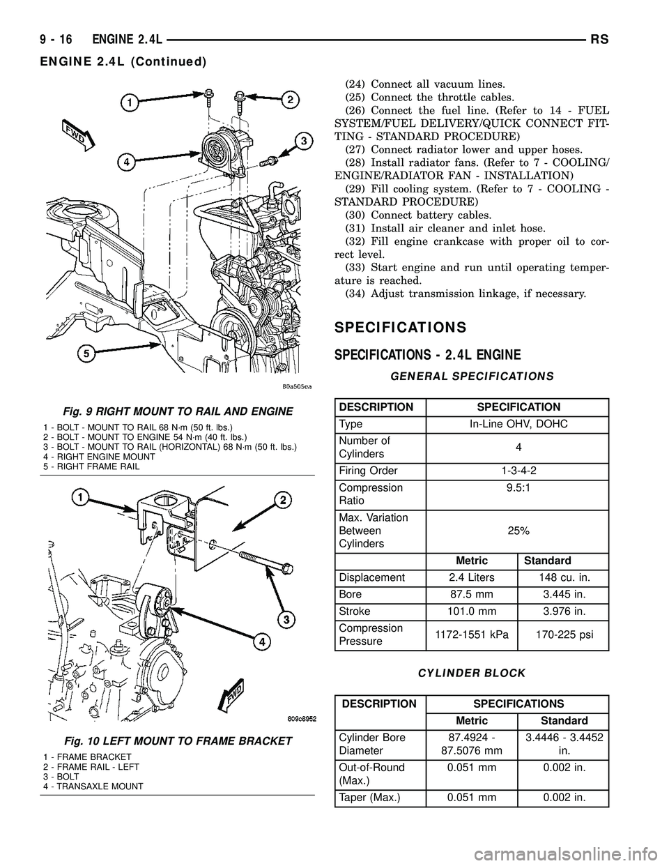
Fig. 9 RIGHT MOUNT TO RAIL AND ENGINE
1 - BOLT - MOUNT TO RAIL 68 N´m (50 ft. lbs.)
2 - BOLT - MOUNT TO ENGINE 54 N´m (40 ft. lbs.)
3 - BOLT - MOUNT TO RAIL (HORIZONTAL) 68 N´m (50 ft. lbs.)
4 - RIGHT ENGINE MOUNT
5 - RIGHT FRAME RAIL
Fig. 10 LEFT MOUNT TO FRAME BRACKET
1 - FRAME BRACKET
2 - FRAME RAIL - LEFT
3 - BOLT
4 - TRANSAXLE MOUNT
9 - 16 ENGINE 2.4LRS
ENGINE 2.4L (Continued)
Page 1194 of 2339
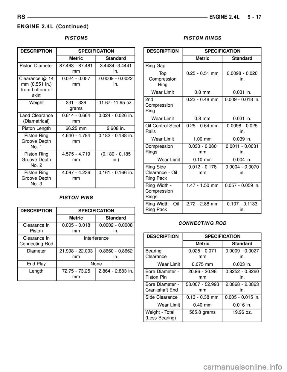
PISTONS
DESCRIPTION SPECIFICATION
Metric Standard
Piston Diameter 87.463 - 87.481
mm3.4434 -3.4441
in.
Clearance @ 14
mm (0.551 in.)
from bottom of
skirt0.024 - 0.057
mm0.0009 - 0.0022
in.
Weight 331 - 339
grams11.67- 11.95 oz.
Land Clearance
(Diametrical)0.614 - 0.664
mm0.024 - 0.026 in.
Piston Length 66.25 mm 2.608 in.
Piston Ring
Groove Depth
No. 14.640 - 4.784
mm0.182 - 0.188 in.
Piston Ring
Groove Depth
No. 24.575 - 4.719
mm(0.180 - 0.185
in.)
Piston Ring
Groove Depth
No. 34.097 - 4.236
mm0.161 - 0.166 in.
PISTON PINS
DESCRIPTION SPECIFICATION
Metric Standard
Clearance in
Piston0.005 - 0.018
mm0.0002 - 0.0008
in.
Clearance in
Connecting RodInterference
Diameter 21.998 - 22.003
mm0.8660 - 0.8662
in.
End Play None
Length 72.75 - 73.25
mm2.864 - 2.883 in.
PISTON RINGS
DESCRIPTION SPECIFICATION
Metric Standard
Ring Gap
To p
Compression
Ring0.25 - 0.51 mm 0.0098 - 0.020
in.
Wear Limit 0.8 mm 0.031 in.
2nd
Compression
Ring0.23 - 0.48 mm 0.009 - 0.018 in.
Wear Limit 0.8 mm 0.031 in.
Oil Control Steel
Rails0.25 - 0.64 mm 0.0098 - 0.025
in.
Wear Limit 1.00 mm 0.039 in.
Compression
Rings0.030 - 0.080
mm0.0011 - 0.0031
in.
Wear Limit 0.10 mm 0.004 in.
Ring Side
Clearance - Oil
Ring Pack0.012 - 0.178
mm0.0004 - 0.0070
in.
Ring Width -
Compression
Rings1.47 - 1.50 mm 0.057 - 0.059 in.
Ring Width - Oil
Ring Pack2.72 - 2.88 mm 0.107 - 0.1133
in.
CONNECTING ROD
DESCRIPTION SPECIFICATION
Metric Standard
Bearing
Clearance0.025 - 0.071
mm0.0009 - 0.0027
in.
Wear Limit 0.075 mm 0.003 in.
Bore Diameter -
Piston Pin20.96 - 20.98
mm0.8252 - 0.8260
in.
Bore Diameter -
Crankshaft End53.007 - 52.993
mm2.0868 - 2.0863
in.
Side Clearance 0.13 - 0.38 mm 0.005 - 0.015 in.
Wear Limit 0.40 mm 0.016 in.
Weight - Total
(Less Bearing)565.8 grams 19.96 oz.
RSENGINE 2.4L9-17
ENGINE 2.4L (Continued)
Page 1208 of 2339
INSTALLATION
CAUTION: Ensure that NONE of the pistons are at
top dead center when installing the camshafts.
(1) Lubricate all camshaft bearing journals, rocker
arms and camshaft lobes.
(2) Install all rocker arms in original positions, if
reused.
(3) Position camshafts on cylinder head bearing
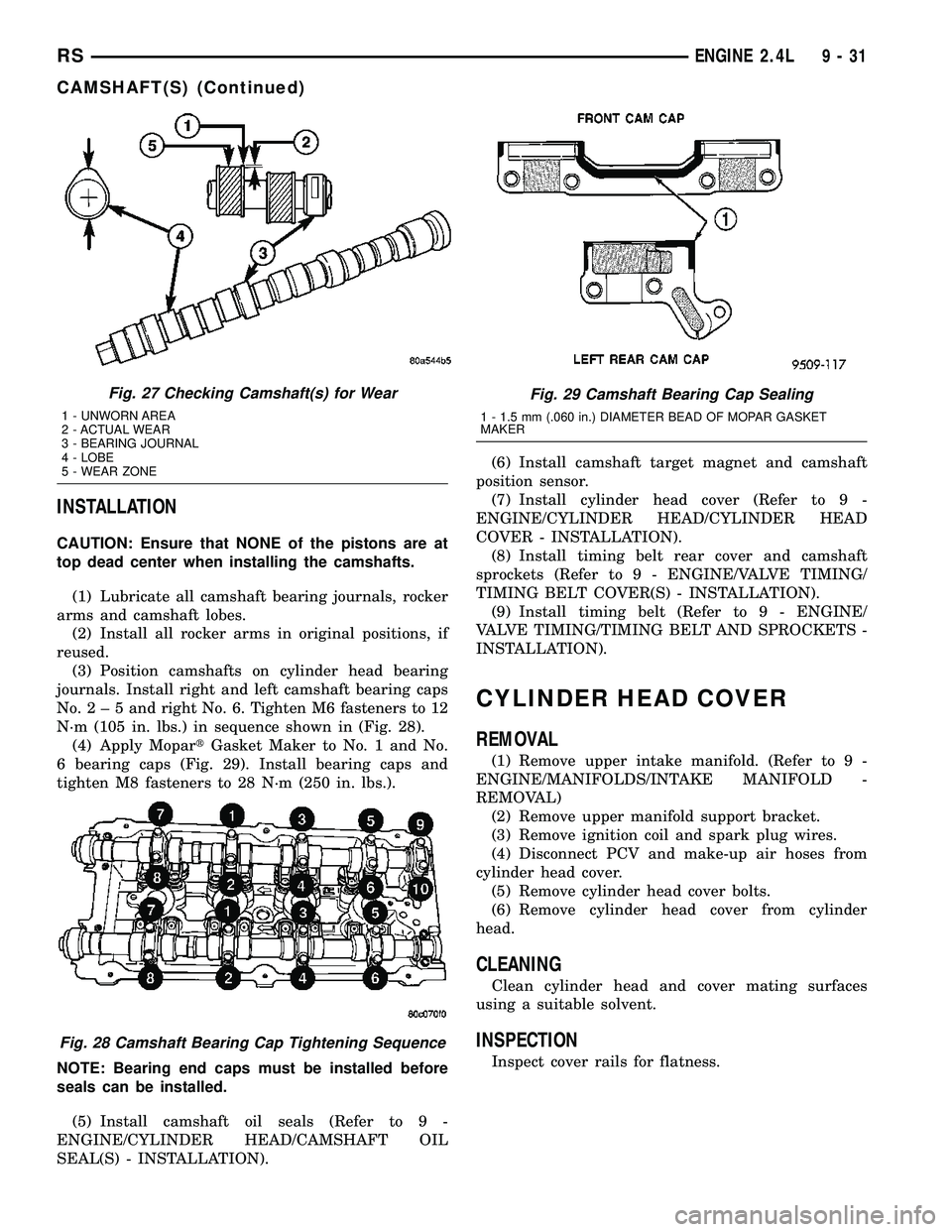
journals. Install right and left camshaft bearing caps
No.2±5andright No. 6. Tighten M6 fasteners to 12
N´m (105 in. lbs.) in sequence shown in (Fig. 28).
(4) Apply MopartGasket Maker to No. 1 and No.
6 bearing caps (Fig. 29). Install bearing caps and
tighten M8 fasteners to 28 N´m (250 in. lbs.).
NOTE: Bearing end caps must be installed before
seals can be installed.
(5) Install camshaft oil seals (Refer to 9 -
ENGINE/CYLINDER HEAD/CAMSHAFT OIL
SEAL(S) - INSTALLATION).(6) Install camshaft target magnet and camshaft
position sensor.
(7) Install cylinder head cover (Refer to 9 -
ENGINE/CYLINDER HEAD/CYLINDER HEAD
COVER - INSTALLATION).
(8) Install timing belt rear cover and camshaft
sprockets (Refer to 9 - ENGINE/VALVE TIMING/
TIMING BELT COVER(S) - INSTALLATION).
(9) Install timing belt (Refer to 9 - ENGINE/
VALVE TIMING/TIMING BELT AND SPROCKETS -
INSTALLATION).
CYLINDER HEAD COVER
REMOVAL
(1) Remove upper intake manifold. (Refer to 9 -
ENGINE/MANIFOLDS/INTAKE MANIFOLD -
REMOVAL)
(2) Remove upper manifold support bracket.
(3) Remove ignition coil and spark plug wires.
(4) Disconnect PCV and make-up air hoses from
cylinder head cover.
(5) Remove cylinder head cover bolts.
(6) Remove cylinder head cover from cylinder
head.
CLEANING
Clean cylinder head and cover mating surfaces
using a suitable solvent.
INSPECTION
Inspect cover rails for flatness.
Fig. 27 Checking Camshaft(s) for Wear
1 - UNWORN AREA
2 - ACTUAL WEAR
3 - BEARING JOURNAL
4 - LOBE
5 - WEAR ZONE
Fig. 28 Camshaft Bearing Cap Tightening Sequence
Fig. 29 Camshaft Bearing Cap Sealing
1 - 1.5 mm (.060 in.) DIAMETER BEAD OF MOPAR GASKET
MAKER
RSENGINE 2.4L9-31
CAMSHAFT(S) (Continued)
Page 1222 of 2339
(4) Remove top ridge of cylinder bores with a reli-
able ridge reamer before removing pistons from cyl-
inder block.Be sure to keep tops of pistons
covered during this operation.
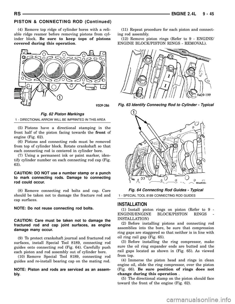
(5) Pistons have a directional stamping in the
front half of the piston facing towards thefrontof
engine (Fig. 62).
(6) Pistons and connecting rods must be removed
from top of cylinder block. Rotate crankshaft so that
each connecting rod is centered in cylinder bore.
(7) Using a permanent ink or paint marker, iden-
tify cylinder number on each connecting rod cap (Fig.
63).
CAUTION: DO NOT use a number stamp or a punch
to mark connecting rods. Damage to connecting
rod could occur.
(8) Remove connecting rod bolts and cap. Care
should be taken not to damage the fracture rod and
cap surfaces.
NOTE: Do not reuse connecting rod bolts.
CAUTION: Care must be taken not to damage the
fractured rod and cap joint surfaces, as engine
damage many occur.
(9) To protect crankshaft journal and fractured rod
surfaces, install Special Tool 8189, connecting rod
guides onto connecting rod (Fig. 64). Carefully push
each piston and rod assembly out of cylinder bore.
(10) Remove Special Tool 8189, connecting rod
guides and re-install bearing cap on the mating rod.
NOTE: Piston and rods are serviced as an assem-
bly.(11) Repeat procedure for each piston and connect-
ing rod assembly.
(12) Remove piston rings (Refer to 9 - ENGINE/
ENGINE BLOCK/PISTON RINGS - REMOVAL).
INSTALLATION
(1) Install piston rings on piston (Refer to 9 -
ENGINE/ENGINE BLOCK/PISTON RINGS -
INSTALLATION)
(2) Before installing pistons and connecting rod
assemblies into the bore, be sure that compression
ring gaps are staggered so that neither is in line with
oil ring rail gap (Fig. 65).
(3) Before installing the ring compressor, make
sure the oil ring expander ends are butted and the
rail gaps located as shown in (Fig. 65). As viewed
from top.
(4) Immerse the piston head and rings in clean
engine oil, slide the ring compressor, over the piston
(Fig. 66).Be sure position of rings does not
change during this operation.
(5) The directional stamp on the piston should face
toward the front of the engine (Fig. 62).
Fig. 62 Piston Markings
1 - DIRECTIONAL ARROW WILL BE IMPRINTED IN THIS AREA
Fig. 63 Identify Connectng Rod to Cylinder - Typical
Fig. 64 Connecting Rod Guides - Typical
1 - SPECIAL TOOL 8189 CONNECTING ROD GUIDES
RSENGINE 2.4L9-45
PISTON & CONNECTING ROD (Continued)
Page 1223 of 2339
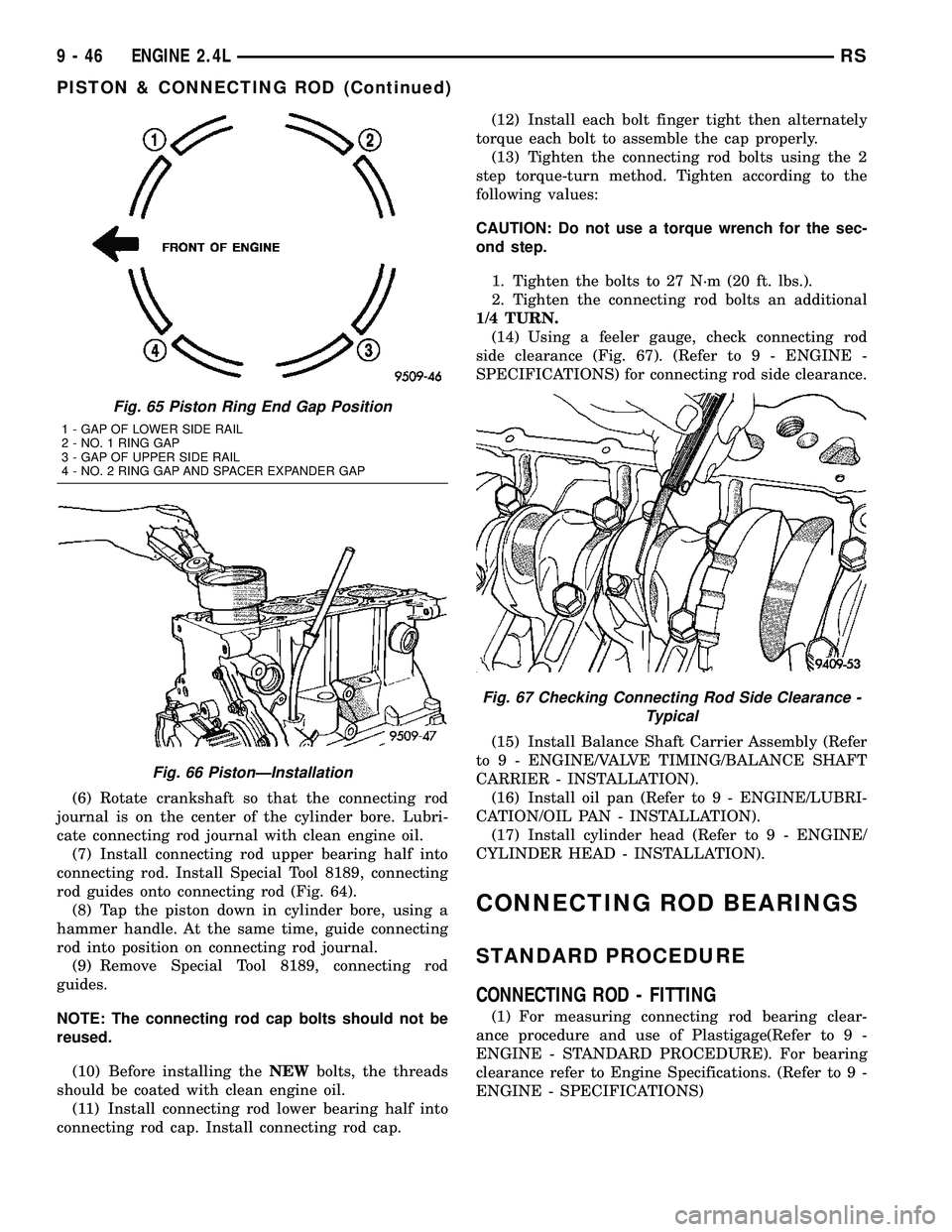
(6) Rotate crankshaft so that the connecting rod
journal is on the center of the cylinder bore. Lubri-
cate connecting rod journal with clean engine oil.
(7) Install connecting rod upper bearing half into
connecting rod. Install Special Tool 8189, connecting
rod guides onto connecting rod (Fig. 64).
(8) Tap the piston down in cylinder bore, using a
hammer handle. At the same time, guide connecting
rod into position on connecting rod journal.
(9) Remove Special Tool 8189, connecting rod
guides.
NOTE: The connecting rod cap bolts should not be
reused.
(10) Before installing theNEWbolts, the threads
should be coated with clean engine oil.
(11) Install connecting rod lower bearing half into
connecting rod cap. Install connecting rod cap.(12) Install each bolt finger tight then alternately
torque each bolt to assemble the cap properly.
(13) Tighten the connecting rod bolts using the 2
step torque-turn method. Tighten according to the
following values:
CAUTION: Do not use a torque wrench for the sec-
ond step.
1. Tighten the bolts to 27 N´m (20 ft. lbs.).
2. Tighten the connecting rod bolts an additional
1/4 TURN.
(14) Using a feeler gauge, check connecting rod
side clearance (Fig. 67). (Refer to 9 - ENGINE -
SPECIFICATIONS) for connecting rod side clearance.
(15) Install Balance Shaft Carrier Assembly (Refer
to 9 - ENGINE/VALVE TIMING/BALANCE SHAFT
CARRIER - INSTALLATION).
(16) Install oil pan (Refer to 9 - ENGINE/LUBRI-
CATION/OIL PAN - INSTALLATION).
(17) Install cylinder head (Refer to 9 - ENGINE/
CYLINDER HEAD - INSTALLATION).
CONNECTING ROD BEARINGS
STANDARD PROCEDURE
CONNECTING ROD - FITTING
(1) For measuring connecting rod bearing clear-
ance procedure and use of Plastigage(Refer to 9 -
ENGINE - STANDARD PROCEDURE). For bearing
clearance refer to Engine Specifications. (Refer to 9 -
ENGINE - SPECIFICATIONS)
Fig. 65 Piston Ring End Gap Position
1 - GAP OF LOWER SIDE RAIL
2 - NO. 1 RING GAP
3 - GAP OF UPPER SIDE RAIL
4 - NO. 2 RING GAP AND SPACER EXPANDER GAP
Fig. 66 PistonÐInstallation
Fig. 67 Checking Connecting Rod Side Clearance -
Typical
9 - 46 ENGINE 2.4LRS
PISTON & CONNECTING ROD (Continued)
Page 1224 of 2339
NOTE: The rod bearing bolts should not be reused.
(2) Before installing theNEWbolts the threads
should be oiled with clean engine oil.
(3) Install each bolt finger tight then alternately
torque each bolt to assemble the cap properly.
(4) Tighten the connecting rod bolts using the 2
step torque-turn method. Tighten according to the
following values:
CAUTION: Do not use a torque wrench for the sec-
ond step.
1. Tighten the bolts to 27 N´m (20 ft. lbs.).
2. Tighten the connecting rod bolts an additional
1/4 TURN.
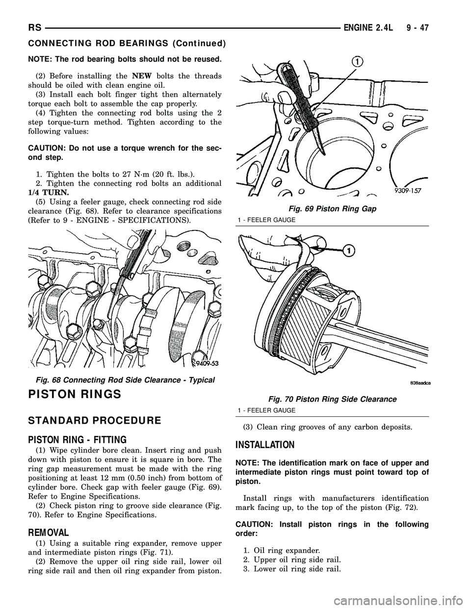
(5) Using a feeler gauge, check connecting rod side
clearance (Fig. 68). Refer to clearance specifications
(Refer to 9 - ENGINE - SPECIFICATIONS).
PISTON RINGS
STANDARD PROCEDURE
PISTON RING - FITTING
(1) Wipe cylinder bore clean. Insert ring and push
down with piston to ensure it is square in bore. The
ring gap measurement must be made with the ring
positioning at least 12 mm (0.50 inch) from bottom of
cylinder bore. Check gap with feeler gauge (Fig. 69).
Refer to Engine Specifications.
(2) Check piston ring to groove side clearance (Fig.
70). Refer to Engine Specifications.
REMOVAL
(1) Using a suitable ring expander, remove upper
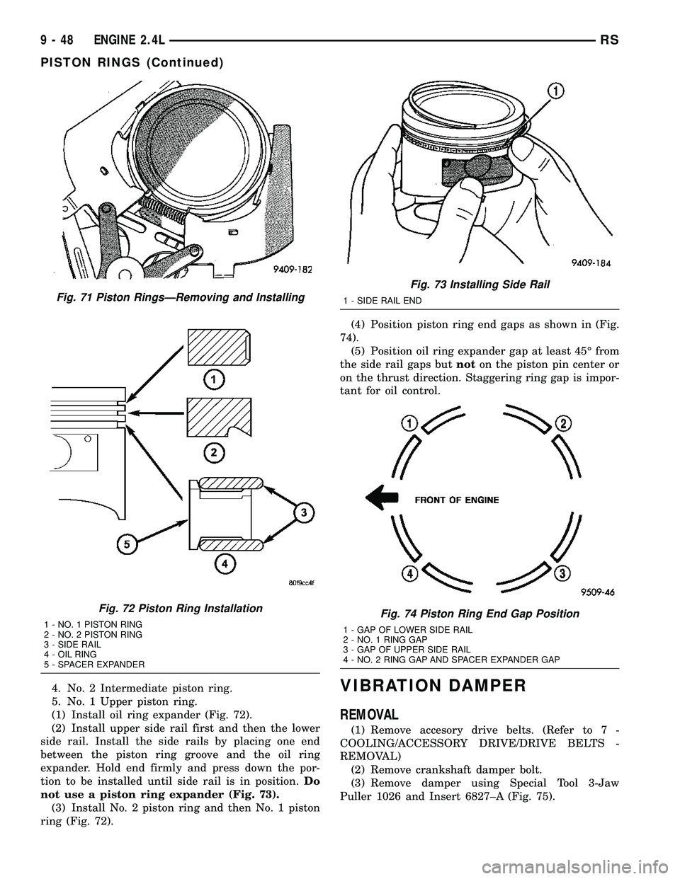
and intermediate piston rings (Fig. 71).
(2) Remove the upper oil ring side rail, lower oil
ring side rail and then oil ring expander from piston.(3) Clean ring grooves of any carbon deposits.
INSTALLATION
NOTE: The identification mark on face of upper and
intermediate piston rings must point toward top of
piston.
Install rings with manufacturers identification
mark facing up, to the top of the piston (Fig. 72).
CAUTION: Install piston rings in the following
order:
1. Oil ring expander.
2. Upper oil ring side rail.
3. Lower oil ring side rail.
Fig. 68 Connecting Rod Side Clearance - Typical
Fig. 69 Piston Ring Gap
1 - FEELER GAUGE
Fig. 70 Piston Ring Side Clearance
1 - FEELER GAUGE
RSENGINE 2.4L9-47
CONNECTING ROD BEARINGS (Continued)
Page 1225 of 2339
4. No. 2 Intermediate piston ring.
5. No. 1 Upper piston ring.
(1) Install oil ring expander (Fig. 72).
(2) Install upper side rail first and then the lower
side rail. Install the side rails by placing one end
between the piston ring groove and the oil ring
expander. Hold end firmly and press down the por-
tion to be installed until side rail is in position.Do
not use a piston ring expander (Fig. 73).
(3) Install No. 2 piston ring and then No. 1 piston
ring (Fig. 72).(4) Position piston ring end gaps as shown in (Fig.
74).
(5) Position oil ring expander gap at least 45É from
the side rail gaps butnoton the piston pin center or
on the thrust direction. Staggering ring gap is impor-
tant for oil control.VIBRATION DAMPER
REMOVAL
(1) Remove accesory drive belts. (Refer to 7 -
COOLING/ACCESSORY DRIVE/DRIVE BELTS -
REMOVAL)
(2) Remove crankshaft damper bolt.
(3) Remove damper using Special Tool 3-Jaw
Puller 1026 and Insert 6827±A (Fig. 75).
Fig. 71 Piston RingsÐRemoving and Installing
Fig. 72 Piston Ring Installation
1 - NO. 1 PISTON RING
2 - NO. 2 PISTON RING
3 - SIDE RAIL
4 - OIL RING
5 - SPACER EXPANDER
Fig. 73 Installing Side Rail
1 - SIDE RAIL END
Fig. 74 Piston Ring End Gap Position
1 - GAP OF LOWER SIDE RAIL
2 - NO. 1 RING GAP
3 - GAP OF UPPER SIDE RAIL
4 - NO. 2 RING GAP AND SPACER EXPANDER GAP
9 - 48 ENGINE 2.4LRS
PISTON RINGS (Continued)
Page 1227 of 2339
ENGINE MOUNTING
DESCRIPTION
The engine mounting system consist of four
mounts; right and a left side support the powertrain,
and a front and a rear mount control powertrain
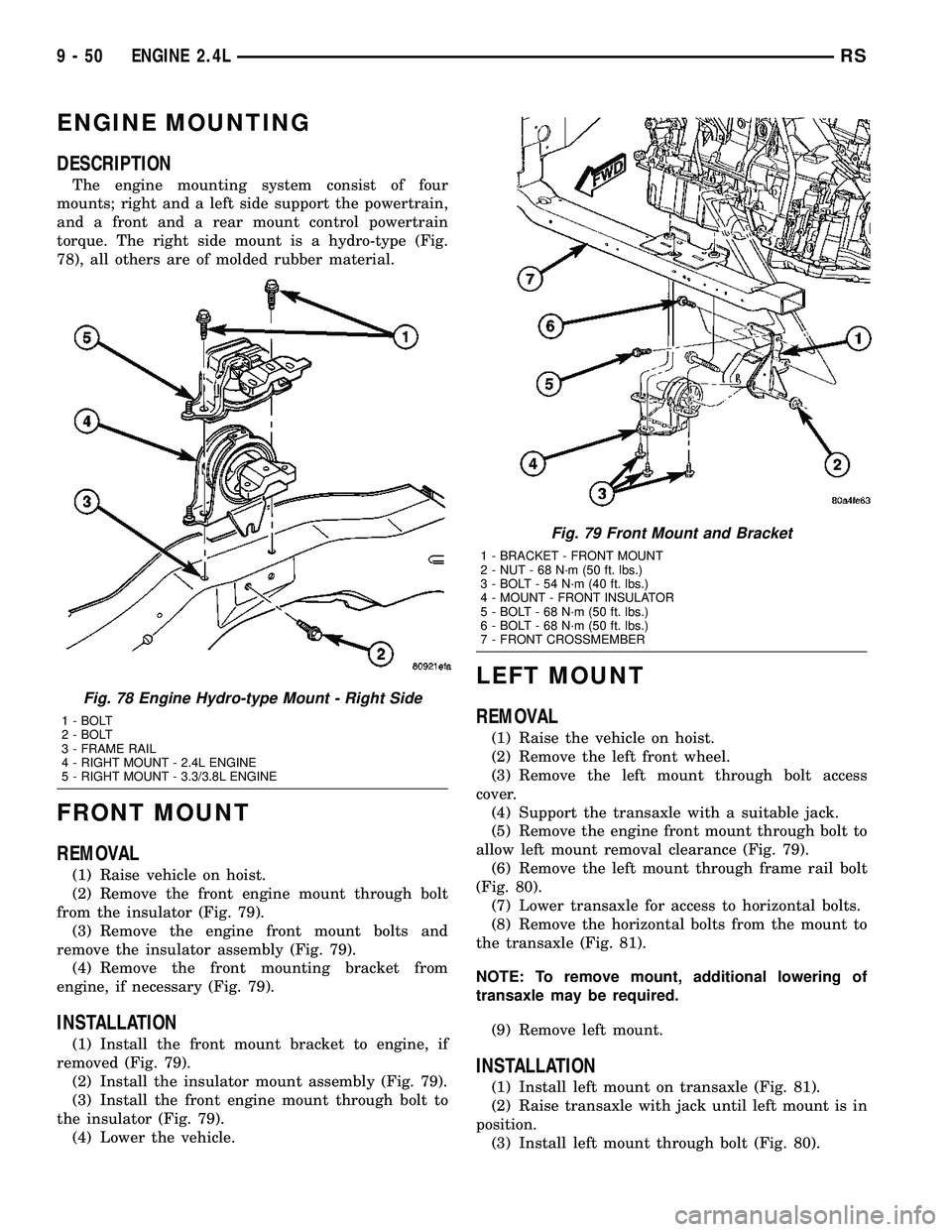
torque. The right side mount is a hydro-type (Fig.
78), all others are of molded rubber material.
FRONT MOUNT
REMOVAL
(1) Raise vehicle on hoist.
(2) Remove the front engine mount through bolt
from the insulator (Fig. 79).
(3) Remove the engine front mount bolts and
remove the insulator assembly (Fig. 79).
(4) Remove the front mounting bracket from
engine, if necessary (Fig. 79).
INSTALLATION
(1) Install the front mount bracket to engine, if
removed (Fig. 79).
(2) Install the insulator mount assembly (Fig. 79).
(3) Install the front engine mount through bolt to
the insulator (Fig. 79).
(4) Lower the vehicle.
LEFT MOUNT
REMOVAL
(1) Raise the vehicle on hoist.
(2) Remove the left front wheel.
(3) Remove the left mount through bolt access
cover.
(4) Support the transaxle with a suitable jack.
(5) Remove the engine front mount through bolt to
allow left mount removal clearance (Fig. 79).
(6) Remove the left mount through frame rail bolt
(Fig. 80).
(7) Lower transaxle for access to horizontal bolts.
(8) Remove the horizontal bolts from the mount to
the transaxle (Fig. 81).
NOTE: To remove mount, additional lowering of
transaxle may be required.
(9) Remove left mount.
INSTALLATION
(1) Install left mount on transaxle (Fig. 81).
(2) Raise transaxle with jack until left mount is in
position.
(3) Install left mount through bolt (Fig. 80).
Fig. 78 Engine Hydro-type Mount - Right Side
1 - BOLT
2 - BOLT
3 - FRAME RAIL
4 - RIGHT MOUNT - 2.4L ENGINE
5 - RIGHT MOUNT - 3.3/3.8L ENGINE
Fig. 79 Front Mount and Bracket
1 - BRACKET - FRONT MOUNT
2 - NUT - 68 N´m (50 ft. lbs.)
3 - BOLT - 54 N´m (40 ft. lbs.)
4 - MOUNT - FRONT INSULATOR
5 - BOLT - 68 N´m (50 ft. lbs.)
6 - BOLT - 68 N´m (50 ft. lbs.)
7 - FRONT CROSSMEMBER
9 - 50 ENGINE 2.4LRS