2005 CHRYSLER VOYAGER wiring
[x] Cancel search: wiringPage 2209 of 2339
DIAGNOSIS AND TESTING
REAR BLOWER MOTOR
BLOWER MOTOR INOPERATIVE
For circuit descriptions and diagrams, refer to the
appropriate wiring information. The wiring informa-
tion includes wiring, diagrams, proper wire and con-
nector repair procedures, further details on wire
harness routing and retention, as well as pin-out and
location views for the various wire harness connec-
tors, splices and grounds.
BLOWER MOTOR ELECTRICAL DIAGNOSIS
(1) Check the fuse (Fuse 12 - 25 ampere) in the
Integrated Power Module (IPM). If OK, go to Step 2.
If not OK, repair the shorted circuit or component as
required and replace the faulty fuse.
(2) Turn the ignition switch to the On position. Be
certain that the rear A/C-heater control power is
turned on. Check for battery voltage at the fuse
(Fuse 12 - 25 ampere) in the IPM. If OK, go to Step
3. If not OK, check the rear blower motor relay.
(3) Turn the ignition switch to the Off position.
Disconnect and isolate the battery negative cable.
Disconnect the rear HVAC wire harness connector
from the rear blower motor resistor block (Manual
Temperature Control) or the rear blower motor power
module (Automatic Temperature Control). Reconnect
the battery negative cable. Turn the ignition switch
to the On position. Be certain that the rear A/C-
heater control power is turned on. Check for battery
voltage at the fused rear blower motor relay output
circuit cavity of the rear HVAC wire harness connec-
tor for the rear blower motor resistor block (MTC) or
the rear blower motor power module (ATC). If OK, go
to Step 4. If not OK, repair the open fused front
blower motor relay output circuit to the IPM as
required.
(4) Turn the ignition switch to the Off position.
Disconnect and isolate the battery negative cable.Disconnect the rear blower motor pigtail wire connec-
tor from the rear HVAC wire harness (MTC) or the
rear blower power module (ATC). Use jumper wires
to connect a battery and ground feeds to the blower
motor pigtail wire connector. The rear blower motor
should operate. If OK with MTC, proceed to diagno-
sis of the rear blower motor resistor block (Refer to
24 - HEATING & AIR CONDITIONING/CONTROLS
- REAR/BLOWER MOTOR RESISTOR - DIAGNOSIS
AND TESTING). If OK with ATC, use a DRBIII scan
tool to diagnose the rear blower motor power module.
Refer to the appropriate diagnostic information. If
not OK with MTC or ATC, replace the faulty rear
blower motor.
BLOWER MOTOR NOISE OR VIBRATION
Refer to the Blower Motor Noise/Vibration Diagno-
sis chart for basic checks of the blower motor when a
vibration or noise is present (Fig. 3).
REMOVAL
WARNING: REFER TO THE APPLICABLE WARN-
INGS AND CAUTIONS FOR THIS SYSTEM BEFORE
PERFORMING THE FOLLOWING OPERATION (Refer
to 24 - HEATING & AIR CONDITIONING/PLUMBING -
WARNING) and (Refer to 24 - HEATING & AIR CON-
DITIONING/PLUMBING - CAUTION).
(1) Remove the rear HVAC housing from the vehi-
cle (Refer to 24 - HEATING & AIR CONDITIONING/
DISTRIBUTION/HVAC HOUSING - REMOVAL).
(2) Disconnect the rear blower motor pigtail wire
connector.
NOTE: With the Manual Temperature Control sys-
tem, the blower motor pigtail wire is connected to a
take out and connector of the rear HVAC wire har-
ness. With the Automatic Temperature Control sys-
tem , the blower pigtail wire is connected to a
receptacle on the blower motor power module.
24 - 58 DISTRIBUTION - REARRS
BLOWER MOTOR (Continued)
Page 2264 of 2339
CABIN HEATER
TABLE OF CONTENTS
page page
CABIN HEATER
DESCRIPTION........................113
OPERATION
MANUAL TEMPERATURE CONTROL
SYSTEM...........................113
AUTOMATIC TEMPERATURE CONTROL
SYSTEM...........................114
WARNING............................114
DIAGNOSIS AND TESTING
SUPPLEMENTAL CABIN HEATER........114
AIR INTAKE PIPE
REMOVAL............................115
INSTALLATION........................115
EXHAUST TUBE
REMOVAL............................116
INSTALLATION........................116
FUEL DOSING PUMP
DESCRIPTION........................117
OPERATION..........................117REMOVAL............................117
INSTALLATION........................117
FUEL LINE
STANDARD PROCEDURE
CLEANING..........................118
REMOVAL............................118
INSTALLATION........................118
HEATER HOSES
REMOVAL............................119
INSTALLATION........................119
HEATER PIPES
REMOVAL............................119
INSTALLATION........................120
HEATER UNIT
REMOVAL............................121
INSTALLATION........................122
HEATER WIRING
REMOVAL............................122
INSTALLATION........................122
CABIN HEATER
DESCRIPTION
Vehicles equipped with the diesel engine are also
equipped with a supplemental cabin heater. This
cabin heater is mounted under the vehicle and oper-
ates similar to an oil fired furnace. The heater burns
small amounts of fuel to provide additional heat to
the coolant. Coolant is routed from the engine, to the
supplemental cabin heater and then to the front
heater core. This provides additional heat to the pas-
senger compartment. The supplemental cabin heater
system is interfaced to the vehicles on-board com-
puter systems and DRBIIItdiagnostics.
The supplemental cabin heater has an electronic
control module that monitors the heat output of the
heater. The cabin heater operates at full load (5 kW),
half load or idle mode (no additional heat) depending
on engine coolant temperature.
When ambient temperatures are lower than 15É C
(60É F), the supplemental cabin heater automatically
operates once each ignition cycle for five minutes.
This assures a good fuel supply is always present for
the supplemental cabin heater.
OPERATION
MANUAL TEMPERATURE CONTROL SYSTEM
The supplemental cabin heater is activated via the
temperature slide control or knob on the A/C-heater
control when equipped with the manual temperature
control (MTC) system. If the slide control or knob is
moved to or above the upper set point the cabin
heater is activated. The cabin heater can operate in a
full or partial load range as well as an idle mode all
dependent on the engine coolant temperature. The
cabin heater will also turn off if the A/C-heater tem-
perature control is lowered to less than the lower set
point. The cabin heater can take up to three minutes
to completely shut down when either the heater tem-
perature is set below the lower set point or the vehi-
cle ignition is shut down.
NOTE: Do not apply a strong vacuum source such
as a garage ventilation system directly on the sup-
plemental cabin heater exhaust line. Too strong of a
vacuum can prevent the supplemental cabin heater
from starting. If required, place the vacuum source
at least 75 mm (3 in.) away from the exhaust line.
RSCABIN HEATER24 - 113
Page 2268 of 2339
FUEL DOSING PUMP
DESCRIPTION
The dosing pump is a combined delivery, dosing
and shut-off system for the fuel supply to the supple-
mental cabin heater from the vehicle fuel tank.
OPERATION
The dosing pump is an electrically operated pump
that receives its operation instructions from the sup-
plemental cabin heater control module. The pump
supplies diesel fuel from the vehicle fuel tank to the
cabin heater.
REMOVAL
NOTE: The dosing pump is serviceable without
removing the supplemental cabin heater from the
vehicle.
(1) Disconnect and isolate the negative battery
cable.
CAUTION: Make sure that the hoist is properly posi-
tioned under the vehicle to prevent damage to the
flexible section of the cabin heater exhaust tube.
(2) Raise and support the vehicle.
(3) Disconnect the wiring harness connector to the
dosing pump by depressing the integral spring and
pulling the connector away from the pump.
NOTE: Utilize an approved fuel storage container to
catch any residual fuel that may drain from the
heater fuel hose or the dosing pump.
(4) Remove the clamp that secures the heater fuel
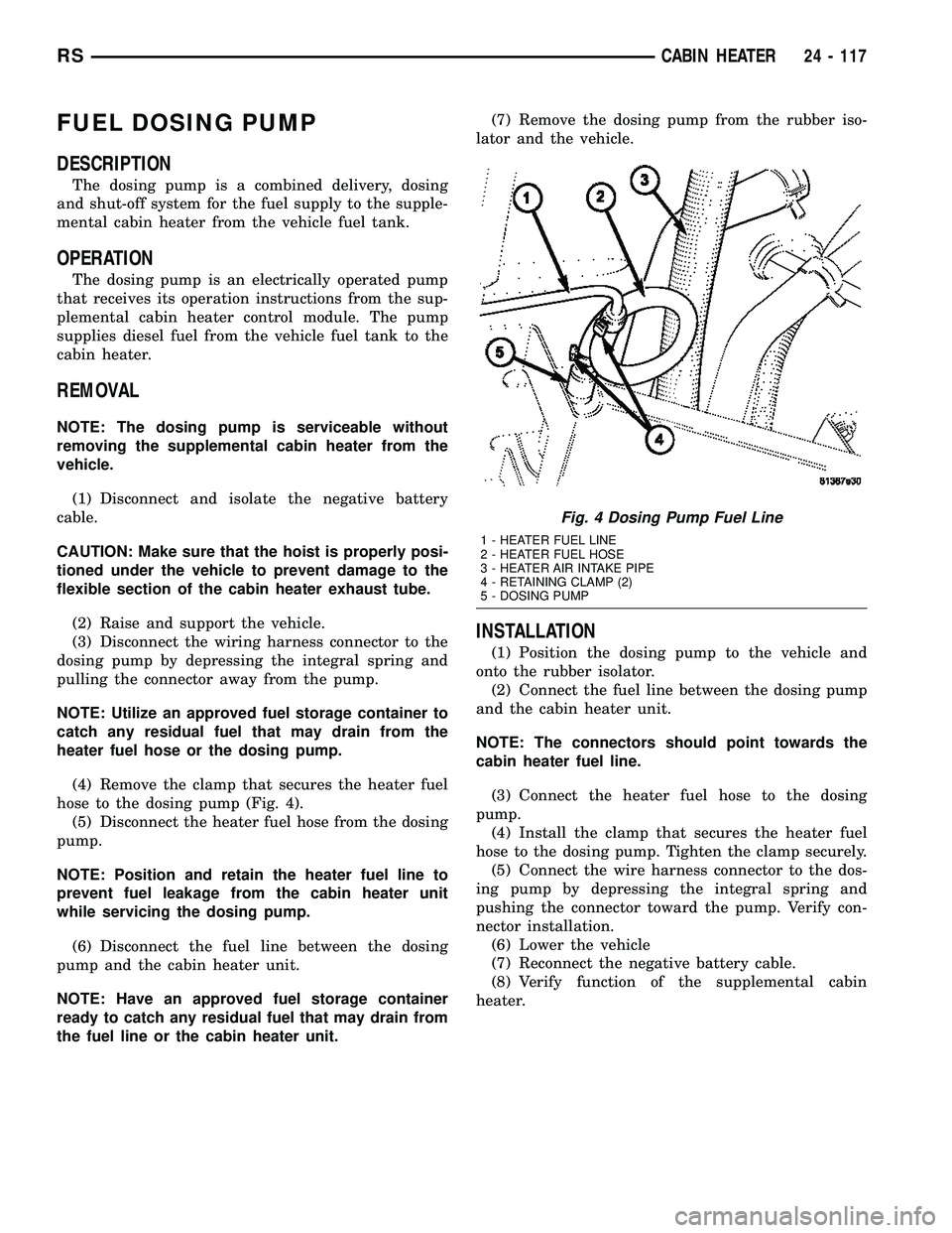
hose to the dosing pump (Fig. 4).
(5) Disconnect the heater fuel hose from the dosing
pump.
NOTE: Position and retain the heater fuel line to
prevent fuel leakage from the cabin heater unit
while servicing the dosing pump.
(6) Disconnect the fuel line between the dosing
pump and the cabin heater unit.
NOTE: Have an approved fuel storage container
ready to catch any residual fuel that may drain from
the fuel line or the cabin heater unit.(7) Remove the dosing pump from the rubber iso-
lator and the vehicle.
INSTALLATION
(1) Position the dosing pump to the vehicle and
onto the rubber isolator.
(2) Connect the fuel line between the dosing pump
and the cabin heater unit.
NOTE: The connectors should point towards the
cabin heater fuel line.
(3) Connect the heater fuel hose to the dosing
pump.
(4) Install the clamp that secures the heater fuel
hose to the dosing pump. Tighten the clamp securely.
(5) Connect the wire harness connector to the dos-
ing pump by depressing the integral spring and
pushing the connector toward the pump. Verify con-
nector installation.
(6) Lower the vehicle
(7) Reconnect the negative battery cable.
(8) Verify function of the supplemental cabin
heater.
Fig. 4 Dosing Pump Fuel Line
1 - HEATER FUEL LINE
2 - HEATER FUEL HOSE
3 - HEATER AIR INTAKE PIPE
4 - RETAINING CLAMP (2)
5 - DOSING PUMP
RSCABIN HEATER24 - 117
Page 2272 of 2339
(7) Connect the heater lines to the heater hoses at
the heater core and EGR port. Position spring clamps
onto the hoses.
(8) Fill the engine cooling system (Refer to 7 -
COOLING - STANDARD PROCEDURE).
HEATER UNIT
REMOVAL
WARNING: DO NOT OPERATE THE DIESEL SUP-
PLEMENTAL CABIN HEATER IN AN ENCLOSED
AREA SUCH AS A GARAGE THAT DOES NOT HAVE
EXHAUST VENTILATION FACILITIES. ALWAYS VENT
THE CABIN HEATER EXHAUST WHEN OPERATING
THE CABIN HEATER. ALLOW THE DIESEL SUPPLE-
MENTAL CABIN HEATER TO COOL BEFORE PER-
FORMING ANY SERVICE PROCEDURES TO THE
CABIN HEATER. VERIFY THAT ALL DIESEL SUP-
PLEMENTAL CABIN HEATER FUEL LINES ARE
SECURELY FASTENED TO THEIR RESPECTIVE
COMPONENTS BEFORE PERFORMING ANY SER-
VICE PROCEDURES TO THE CABIN HEATER. FAIL-
URE TO FOLLOW THESE INSTRUCTION MAY
RESULT IN PERSONAL INJURY OR DEATH.(1) Raise and support the vehicle. Take note of the
location of the flexible section of the cabin heater
exhaust tube.
(2) Drain the engine cooling system (Refer to 7 -
COOLING - STANDARD PROCEDURE).
(3) Carefully open one hose to the underbody tube
assembly and drain the remaining coolant. A salvage
hose is a good idea to control the residual coolant, as
flow will occur from both the cabin heater and the
hose and tube assemblies.
(4) Remove the second hose from the underbody
hose and tube assembly.
(5) Loosen the hose and tube assembly from the
toe-board crossmember at two locations.
(6) Disconnect the electrical connector from the
body harness near the toe-board crossmember and
rail.
(7) Remove the wiring harness from the toe-board
crossmember (Refer to 24 - HEATING & AIR CON-
DITIONING/CABIN HEATER/HEATER UNIT -
REMOVAL).
(8) Open the fuel filler cap. Disconnect the rubber
fuel hose between the body tube assembly and the
fuel pump nipple at the body tube joint. A minimal
amount of fuel may flow from the open port.
NOTE: Utilize an approved fuel storage container to
catch any residual fuel.
(9) Loosen the two fasteners at the rail. Take care
to notice that the exhaust tube bracket tab is on top
of the heater bracket and that there are two spacer
washers installed between the rubber grommets.
(10) Remove the flexible section of the cabin
heater exhaust tube from the exhaust tube by loos-
ening the clamp. Remove the hose from the exhaust
tube. Removal of the rail tube assembly may aid in
this service operation (Refer to 24 - HEATING & AIR
CONDITIONING/CABIN HEATER/EXHAUST TUBE
- REMOVAL).
(11) Remove seat hex nut at the heater mounting
flange to crossmember.
(12) Loosen the remaining fasteners which mount
the exhaust tube assembly to the vehicle.
(a) Install a suitable support device under the
cabin heater and secure the cabin heater to the
support.
(13) Loosen the remaining three fasteners to the
crossmembers.
(14) Remove the loosened fasteners that support
the cabin heater while supporting the weight of the
heater.
(15) Swing the cabin heater mounting bracket
from between the exhaust bracket and rail mounting
location. Drain any residual coolant from the cabin
heater.
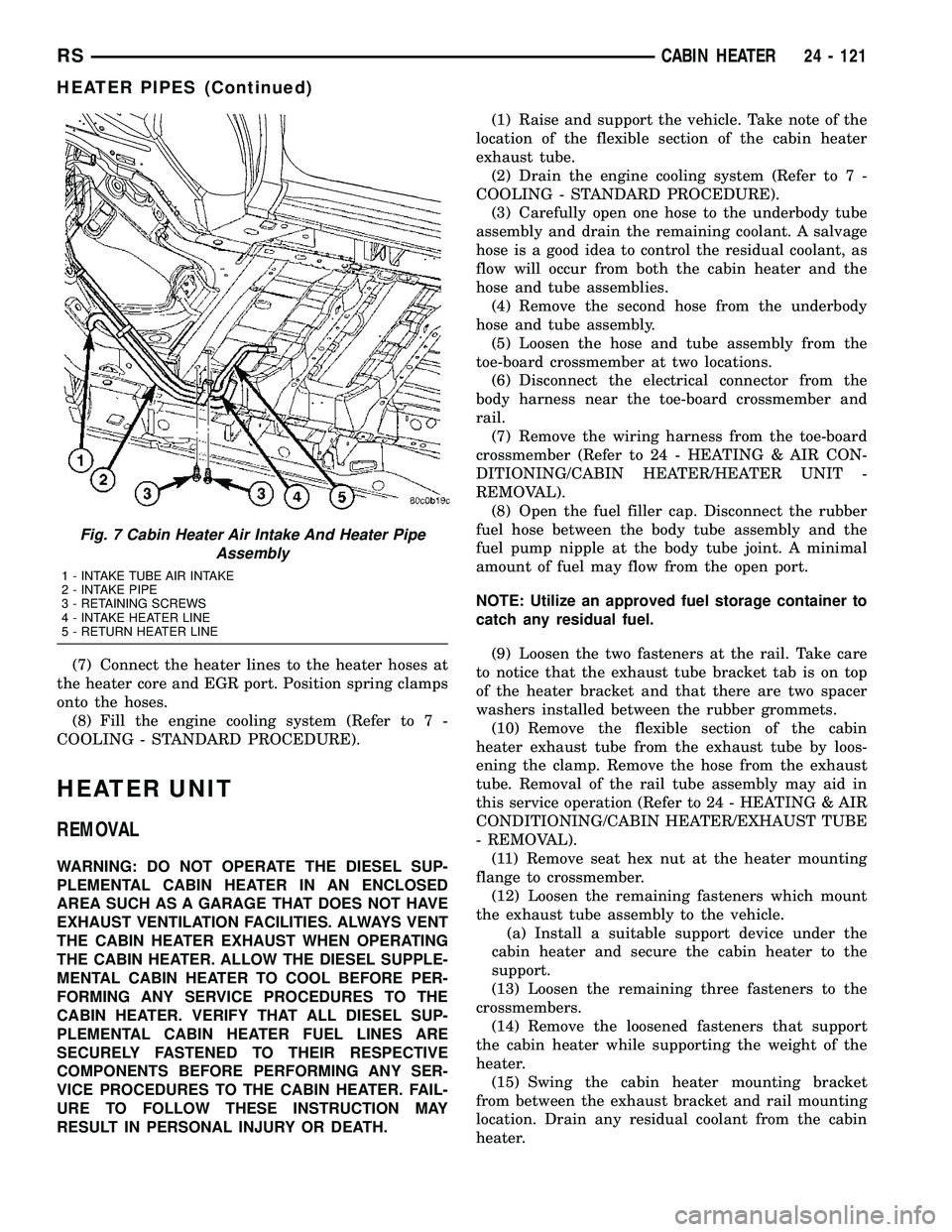
Fig. 7 Cabin Heater Air Intake And Heater Pipe
Assembly
1 - INTAKE TUBE AIR INTAKE
2 - INTAKE PIPE
3 - RETAINING SCREWS
4 - INTAKE HEATER LINE
5 - RETURN HEATER LINE
RSCABIN HEATER24 - 121
HEATER PIPES (Continued)
Page 2273 of 2339
(16) Remove the cabin heater from the vehicle.
INSTALLATION
(1) Install the cabin heater mounting bracket
between the exhaust bracket and the rail mounting
location.
(2) Support the cabin heater and install the fasten-
ers that secure the cabin heater to the mounting
bracket.
(3) Install the three fasteners to the crossmem-
bers. Tighten the M6 fasteners to 7 N´m (62 in. lbs.).
(4) Position the two spacer washers between the
body and the rubber grommets for the two mounting
points on the rail.
(5) Tighten the remaining M6 fasteners to 7 N´m
(62 in. lbs.) and the M8 fasteners to 23 N´m (17 ft.
lbs.) which mount the exhaust tube assembly to the
vehicle.
(6) Install the seat hex nut at the heater mounting
flange to the crossmembers. Tighten the nut to 60
N´m (44 ft. lbs.)
(7) Install the flexible section of the cabin heater
exhaust tube to the exhaust tube. Tighten the M6
bolt of the clamp securley. Install the hose to the
exhaust tube.
(8) Tighten the two M8 fasteners at the rail to 23
N´m (17 ft. lbs.). Taking care so that the exhaust
tube bracket tab is on the top of the heater bracket.
(9) Install the wiring harness (Refer to 24 - HEAT-
ING & AIR CONDITIONING/CABIN HEATER/
HEATER UNIT - INSTALLATION).
(10) Tighten the hose and tube assembly to the
toe-board crossmember at two locations.
(11) Install the second hose to the underbody hose
and tube assembly.
(12) Connect the rubber fuel hose between the
body tube assembly and the fuel pump nipple at the
body tube joint. Close the fuel fill cap.
(13) Remove the cabin heater support device from
under the vehicle.
(14) Lower the vehicle.(15) Fill the engine cooling system (Refer to 7 -
COOLING - STANDARD PROCEDURE).
(16) Verify function of the cabin heater.
HEATER WIRING
REMOVAL
(1) Elevate vehicle on a lift taking note of the
exhaust tube flexible section.
(2) Unplug connector from vehicle wiring harness
to cabin heater harness.
(3) Unplug connector from cabin heater harness to
dosing pump connector.
(4) Unplug two connectors from cabin heater har-
ness to cabin heater controller connectors.
(5) Remove two wiring harness connectors from
underbody.
(6) Remove two wiring harness connectors from
cabin heater shield.
(7) Carefully route the cabin heater harness to the
left side between the cabin heater unit and the cabin
heater shield.
INSTALLATION
(1) Carefully route the cabin heater harness from
the left side of the cabin heater between the cabin
heater unit and the cabin heater shield.
(2) Install the two wiring harness retaining con-
nectors to the cabin heater shield.
(3) Route the wiring harness along the underside
of the vehicle and install the two wiring harness
retaining connectors.
(4) Plug the two connectors from the cabin heater
harness to the cabin heater controller.
(5) Plug the connector to the cabin heater harness
to the dosing pump connector.
(6) Plug the connector from the vehicle wiring har-
ness to the cabin heater harness.
(7) Lower the vehicle.
(8) Verify function of the cabin heater.
24 - 122 CABIN HEATERRS
HEATER UNIT (Continued)
Page 2285 of 2339
SPECIFICATIONS
TORQUE
DESCRIPTION N´m Ft. Lbs. In. Lbs.
PCV VAlve 3.3/3.8L 6.3 55
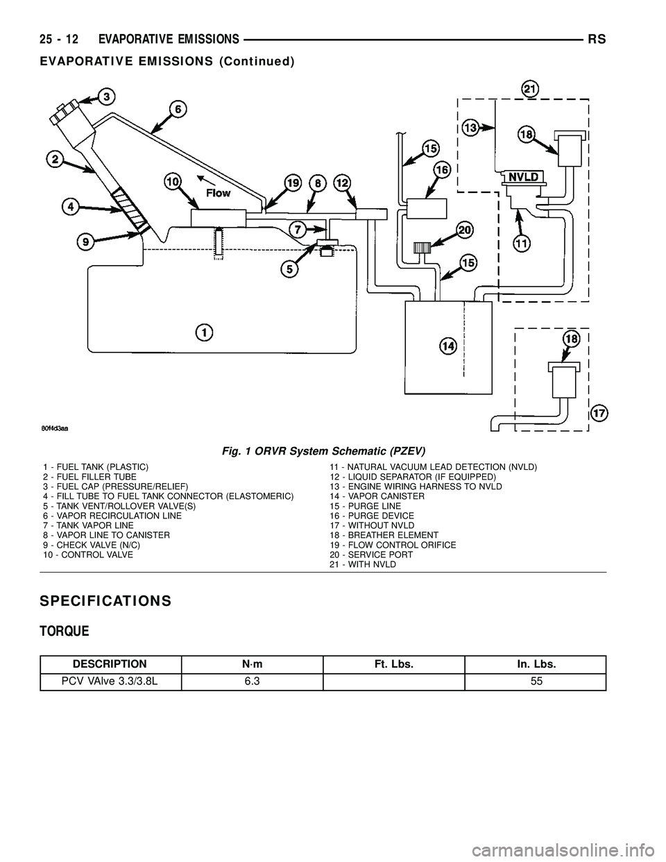
Fig. 1 ORVR System Schematic (PZEV)
1 - FUEL TANK (PLASTIC) 11 - NATURAL VACUUM LEAD DETECTION (NVLD)
2 - FUEL FILLER TUBE 12 - LIQUID SEPARATOR (IF EQUIPPED)
3 - FUEL CAP (PRESSURE/RELIEF) 13 - ENGINE WIRING HARNESS TO NVLD
4 - FILL TUBE TO FUEL TANK CONNECTOR (ELASTOMERIC) 14 - VAPOR CANISTER
5 - TANK VENT/ROLLOVER VALVE(S) 15 - PURGE LINE
6 - VAPOR RECIRCULATION LINE 16 - PURGE DEVICE
7 - TANK VAPOR LINE 17 - WITHOUT NVLD
8 - VAPOR LINE TO CANISTER 18 - BREATHER ELEMENT
9 - CHECK VALVE (N/C) 19 - FLOW CONTROL ORIFICE
10 - CONTROL VALVE 20 - SERVICE PORT
21 - WITH NVLD
25 - 12 EVAPORATIVE EMISSIONSRS
EVAPORATIVE EMISSIONS (Continued)
Page 2289 of 2339
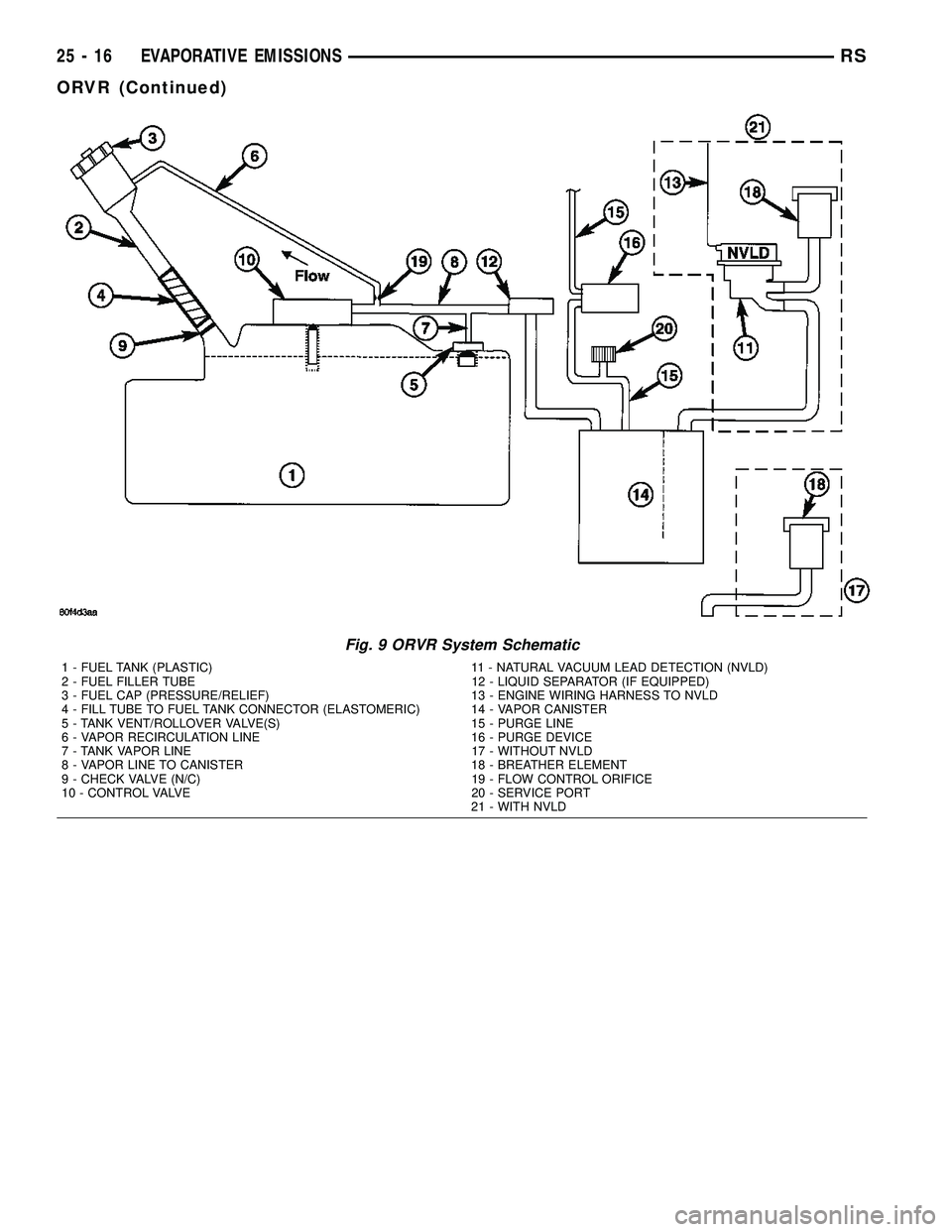
Fig. 9 ORVR System Schematic
1 - FUEL TANK (PLASTIC) 11 - NATURAL VACUUM LEAD DETECTION (NVLD)
2 - FUEL FILLER TUBE 12 - LIQUID SEPARATOR (IF EQUIPPED)
3 - FUEL CAP (PRESSURE/RELIEF) 13 - ENGINE WIRING HARNESS TO NVLD
4 - FILL TUBE TO FUEL TANK CONNECTOR (ELASTOMERIC) 14 - VAPOR CANISTER
5 - TANK VENT/ROLLOVER VALVE(S) 15 - PURGE LINE
6 - VAPOR RECIRCULATION LINE 16 - PURGE DEVICE
7 - TANK VAPOR LINE 17 - WITHOUT NVLD
8 - VAPOR LINE TO CANISTER 18 - BREATHER ELEMENT
9 - CHECK VALVE (N/C) 19 - FLOW CONTROL ORIFICE
10 - CONTROL VALVE 20 - SERVICE PORT
21 - WITH NVLD
25 - 16 EVAPORATIVE EMISSIONSRS
ORVR (Continued)
Page 2311 of 2339
DEFOGGER RELAY - DESCRIPTION,REAR WINDOW ....................... 8G-3
DEFOGGER RELAY - INSTALLATION, REAR WINDOW ....................... 8G-4
DEFOGGER RELAY - OPERATION, REAR WINDOW ............................ 8G-3
DEFOGGER RELAY - REMOVAL, REAR WINDOW ............................ 8G-4
DEFOGGER SWITCH - DESCRIPTION, REAR WINDOW ....................... 8G-4
DEFOGGER SWITCH - OPERATION, REAR WINDOW ............................ 8G-4
DEFROSTER DUCT - INSTALLATION ......24-50
DEFROSTER DUCT - REMOVAL ..........24-49
DEMAGNETIZING, STANDARD PROCEDURE - COMPASS ...............8M-5
DEMISTER DUCTS - INSTALLATION, INSTRUMENT PANEL .................. 24-54
DEMISTER DUCTS - REMOVAL, INSTRUMENT PANEL .................. 24-54
DEMISTER OUTLETS, INSTALLATION - FRONT ............................. 24-45
DEMISTER OUTLETS, REMOVAL - FRONT . 24-44
DEPLOYMENT - STANDARD PROCEDURE, SERVICE AFTER AN
AIRBAG ............................. 8O-7
DETECTION ASSY - INSTALLATION, NATURAL VAC LEAK .................. 25-14
DETECTION ASSY - REMOVAL, NATURAL VAC LEAK .......................... 25-14
DETECTION PUMP - INSTALLATION, LEAK .............................. 25-15
DETECTION PUMP - REMOVAL, LEAK ......25-15
DEVICES - STANDARD PROCEDURE, ELECTROSTATIC DISCHARGE (ESD)
SENSITIVE ........................8W -01-8
DIAGNOSTIC SYSTEM, DIAGNOSIS AND TESTING - ON-BOARD .................8F-22
DIAGNOSTIC TROUBLE CODES - STANDARD PROCEDURE, OBTAINING .....8E-15
DIAGRAMS - 4XTE TRANSAXLE HYDRAULIC SCHEMATICS,
SCHEMATICS .................. 21-199,21-54
DIAGRAMS - DESCRIPTION, HOW TO USE WIRING ......................8W -01-1
DIAGRAMS - SPECIAL TOOLS, SCHEMATICS ........................ 21-68
DIESEL - DESCRIPTION ...............19-52
DIESEL - INSTALLATION ...............19-53
DIESEL - REMOVAL ................... 19-52
DIESEL ENGINE - DESCRIPTION, FUEL REQUIREMENTS .......................0-6
DIESEL ENGINES - DESCRIPTION, ENGINE OIL ...........................0-6
DIESEL ENGINES - EXPORT - DESCRIPTION ........................ 0-21
DIESEL ENGINES, INSTALLATION - 2.5L/2.8L ........................... 24-78
DIESEL ENGINES, REMOVAL - 2.5L/2.8L . . 24-77
DIFFERENTIAL BEARING PRELOAD - ADJUSTMENT ...................... 21-228
DIFFERENTIAL BEARING PRELOAD MEASUREMENT AND ADJUSTMENT,
ADJUSTMENTS ...................... 21-79
DIMENSIONS - FOLD-IN-FLOOR SEATS ONLY - SPECIFICATIONS, FRAME ........13-11
DIMENSIONS - SPECIFICATIONS, BODY OPENING .......................... 23-180
DIMENSIONS - SPECIFICATIONS, FRAME . . . 13-6
DIODE - INSTALLATION ............8W-01-14
DIODE - REMOVAL ................8W -01-14
DISABLED INDICATOR - DESCRIPTION, PASSENGER AIRBAG .................8O-33
DISABLED INDICATOR - INSTALLATION, PASSENGER AIRBAG .................8O-34
DISABLED INDICATOR - OPERATION, PASSENGER AIRBAG .................8O-33
DISABLED INDICATOR - REMOVAL, PASSENGER AIRBAG .................8O-34
DISASSEMBLY/ASSEMBLY - STANDARD PROCEDURE, TRANSMISSION COOLER
LINE QUICK CONNECT FITTING ...........7-38
DISC BRAKE CALIPER - INSTALLATION, REAR ............................... 5-30
DISC BRAKE CALIPER - REMOVAL, REAR ............................... 5-28
DISC BRAKE CALIPER ADAPTER - INSTALLATION, FRONT .................5-31DISC BRAKE CALIPER ADAPTER -
REMOVAL, FRONT ..................... 5-31
DISC BRAKE CALIPER (CONTINENTAL TEVES BRAKES) - INSTALLATION,
FRONT .............................. 5-27
DISC BRAKE CALIPER (CONTINENTAL TEVES BRAKES) - REMOVAL, FRONT ......5-24
DISC BRAKE CALIPER GUIDE PINS (TRW BRAKES) - INSTALLATION ...............5-32
DISC BRAKE CALIPER GUIDE PINS (TRW BRAKES) - REMOVAL .................. 5-31
DISC BRAKE CALIPER (TRW BRAKES) - INSTALLATION, FRONT .................5-27
DISC BRAKE CALIPER (TRW BRAKES) - REMOVAL, FRONT ..................... 5-24
DISC BRAKE SHOES - CLEANING .....5-16,5-18
DISC BRAKE SHOES - INSPECTION . . . 5-16,5-18
DISC BRAKE SHOES - INSTALLATION, REAR ............................... 5-19
DISC BRAKE SHOES - REMOVAL, REAR ....5-17
DISC BRAKE SHOES (CONTINENTAL TEVES BRAKES) - INSTALLATION,
FRONT .............................. 5-16
DISC BRAKE SHOES (CONTINENTAL TEVES BRAKES) - REMOVAL, FRONT ......5-15
DISC BRAKE SHOES (TRW BRAKES) - INSTALLATION, FRONT .................5-17
DISC BRAKE SHOES (TRW BRAKES) - REMOVAL, FRONT ..................... 5-15
DISC BRAKES (EXPORT) - DESCRIPTION . . . 5-13
DISC BRAKES (FRONT) - DESCRIPTION ....5-11
DISC BRAKES (FRONT) - OPERATION ......5-13
DISC BRAKES (REAR) - DESCRIPTION .....5-13
DISC BRAKES (REAR) - OPERATION ......5-14
DISCHARGE (ESD) SENSITIVE DEVICES - STANDARD PROCEDURE,
ELECTROSTATIC ...................8W -01-8
DISCHARGE LINE - INSTALLATION, A/C . . . 24-80
DISCHARGE LINE - REMOVAL, A/C .......24-79
DISPLAY - DESCRIPTION, PARK ASSIST . . . 8B-3
DISPLAY - INSTALLATION, PARK ASSIST . . . 8B-4
DISPLAY - OPERATION, PARK ASSIST .....8B-3
DISPLAY - REMOVAL, PARK ASSIST ......8B-4
DISPLAY TEST MODE, OPERATION - DRB III T STATE .......................... 25-10
DISSASEMBLY, REMOVAL ..............24-51
DISTRIBUTION DUCT - INSTALLATION ....24-57
DISTRIBUTION DUCT - REMOVAL ........24-57
DISTRIBUTION DUCTS - INSTALLATION, FLOOR ............................. 24-50
DISTRIBUTION DUCTS - REMOVAL, FLOOR ............................. 24-50
DISTRIBUTION SYSTEM - DESCRIPTION, POWER ..........................8W -97-1
DISTRIBUTION SYSTEM - OPERATION, POWER ..........................8W -97-1
DISTRIBUTION SYSTEMS, SPECIAL TOOLS - POWER ...................8W -97-1
DOES NOT FILL - DIAGNOSIS AND TESTING, VEHICLE ................... 25-17
DOME/CARGO LAMP - INSTALLATION ....8L-22
DOME/CARGO LAMP - REMOVAL ........8L-22
DOOR - INSTALLATION ................23-15
DOOR - INSTALLATION, FUEL FILL .......23-52
DOOR - INSTALLATION, SLIDING ........23-29
DOOR - REMOVAL .................... 23-15
DOOR - REMOVAL, FUEL FILL ..........23-52
DOOR - REMOVAL, SLIDING ............23-29
DOOR ACTUATOR - DESCRIPTION, BLEND ........................ 24-22,24-34
DOOR ACTUATOR - DESCRIPTION, MODE ............................. 24-29
DOOR ACTUATOR - DESCRIPTION, RECIRCULATION ..................... 24-31
DOOR ACTUATOR - INSTALLATION, BLEND ........................ 24-22,24-35
DOOR ACTUATOR - INSTALLATION, MODE ............................. 24-30
DOOR ACTUATOR - INSTALLATION, RECIRCULATION ..................... 24-32
DOOR ACTUATOR - OPERATION, BLEND . . 24-22,
24-35
DOOR ACTUATOR - OPERATION, MODE . . . 24-29
DOOR ACTUATOR - OPERATION, RECIRCULATION ..................... 24-31
DOOR ACTUATOR - REAR - DESCRIPTION, MODE .................24-39DOOR ACTUATOR - REAR -
INSTALLATION, MODE .................24-40
DOOR ACTUATOR - REAR - OPERATION, MODE ............................. 24-39
DOOR ACTUATOR - REAR - REMOVAL, MODE ............................. 24-39
DOOR ACTUATOR - REMOVAL, BLEND . . . 24-22, 24-35
DOOR ACTUATOR - REMOVAL, MODE ....24-29
DOOR ACTUATOR - REMOVAL, RECIRCULATION ..................... 24-32
DOOR ADJUSTMENT, STANDARD PROCEDURE - POWER SLIDING .........8N-49
DOOR ADJUSTMENTS, ADJUSTMENTS - SLIDING ............................ 23-30
DOOR BLOCKER LATCH - INSTALLATION, FUEL FILL .......................... 23-53
DOOR BLOCKER LATCH - REMOVAL, FUEL FILL .......................... 23-53
DOOR BLOCKER LATCH STRIKER - INSTALLATION, FUEL FILL .............23-53
DOOR BLOCKER LATCH STRIKER - REMOVAL, FUEL FILL .................23-53
DOOR BLOCKER LOCKOUT LINK - INSTALLATION, FUEL FILL .............23-54
DOOR BLOCKER LOCKOUT LINK - REMOVAL, FUEL FILL .................23-54
DOOR CONTROL MODULE - DESCRIPTION, SLIDING ...............8E-18
DOOR CONTROL MODULE - OPERATION, SLIDING ............................ 8E-18
DOOR CONTROL MODULE, DIAGNOSIS AND TESTING - SLIDING ...............8E-18
DOOR CYLINDER LOCK SWITCH - EXPORT - DESCRIPTION ...............8N-22
DOOR CYLINDER LOCK SWITCH - EXPORT - OPERATION ................8N-22
DOOR CYLINDER LOCK SWITCH, EXPORT ............................ 8N-22
DOOR GLASS - INSTALLATION ..........23-17
DOOR GLASS - INSTALLATION, SLIDING . 23-163
DOOR GLASS - REMOVAL .............23-16
DOOR GLASS - REMOVAL, SLIDING .....23-163
DOOR GLASS RUN WEATHERSTRIP - INSTALLATION, FRONT ...............23-166
DOOR GLASS RUN WEATHERSTRIP - REMOVAL, FRONT ................... 23-166
DOOR INNER BELT MOLDING - INSTALLATION, FRONT ...............23-168
DOOR INNER BELT MOLDING - REMOVAL, FRONT ................... 23-168
DOOR LEARN CYCLE, STANDARD PROCEDURE - POWER SLIDING .........8N-48
DOOR LOCK MOTOR - INSTALLATION, SLIDING ........................... 8N-25
DOOR LOCK MOTOR - REMOVAL, SLIDING ........................... 8N-25
DOOR LOCK MOTOR, DIAGNOSIS AND TESTING ........................... 8N-23
DOOR LOCK SWITCH, DIAGNOSIS AND TESTING ........................... 8N-23
DOOR MOTOR - DESCRIPTION, SLIDING . . 8N-51
DOOR MOTOR - INSTALLATION, SLIDING . 8N-51
DOOR MOTOR - OPERATION, SLIDING . . . 8N-51
DOOR MOTOR - REMOVAL, SLIDING .....8N-51
DOOR OUTER BELT MOLDING - INSTALLATION, FRONT ...............23-167
DOOR OUTER BELT MOLDING - REMOVAL, FRONT ................... 23-167
DOOR SILL PLATE - INSTALLATION, SLIDING ............................ 23-99
DOOR SILL PLATE - REMOVAL, SLIDING . . 23-98
DOOR SILL TRIM PLATE - INSTALLATION ....................... 23-89
DOOR SILL TRIM PLATE - REMOVAL .....23-89
DOOR STOP BUMPER BEZEL - INSTALLATION, SLIDING ...............23-25
DOOR STOP BUMPER BEZEL - REMOVAL, SLIDING .................. 23-25
DOOR SYSTEM - DESCRIPTION, POWER SLIDING ........................... 8N-40
DOOR SYSTEM - OPERATION, POWER SLIDING ........................... 8N-41
DOOR SYSTEM, DIAGNOSIS AND TESTING - POWER SLIDING ............8N-42
DOOR WEATHERSTRIP - INSTALLATION, FRONT ............................ 23-168
10 INDEXRS
Description Group-Page Description Group-Page Description Group-Page