2005 CHRYSLER VOYAGER torque
[x] Cancel search: torquePage 1281 of 2339
Remove all gasket material from cylinder head and
block (Refer to 9 - ENGINE - STANDARD PROCE-
DURE). Be careful not to gouge or scratch the alumi-
num head sealing surface.
Clean all engine oil passages.
INSPECTION
(1) Before cleaning, check for leaks, damage and
cracks.
(2) Clean cylinder head and oil passages.
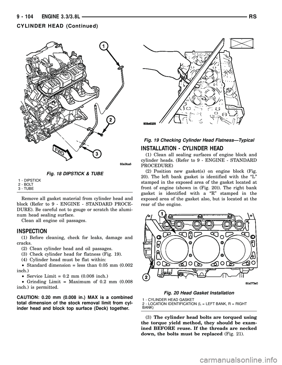
(3) Check cylinder head for flatness (Fig. 19).
(4) Cylinder head must be flat within:
²Standard dimension = less than 0.05 mm (0.002
inch.)
²Service Limit = 0.2 mm (0.008 inch.)
²Grinding Limit = Maximum of 0.2 mm (0.008
inch.) is permitted.
CAUTION: 0.20 mm (0.008 in.) MAX is a combined
total dimension of the stock removal limit from cyl-
inder head and block top surface (Deck) together.
INSTALLATION - CYLINDER HEAD
(1) Clean all sealing surfaces of engine block and
cylinder heads. (Refer to 9 - ENGINE - STANDARD
PROCEDURE)
(2) Position new gasket(s) on engine block (Fig.
20). The left bank gasket is identified with the ªLº
stamped in the exposed area of the gasket located at
front of engine (shown in (Fig. 20)). The right bank
gasket is identified with a ªRº stamped in the
exposed area of the gasket also, but is located at the
rear of the engine.
(3)The cylinder head bolts are torqued using
the torque yield method, they should be exam-
ined BEFORE reuse. If the threads are necked
down, the bolts must be replaced(Fig. 21).
Fig. 18 DIPSTICK & TUBE
1 - DIPSTICK
2 - BOLT
3 - TUBE
Fig. 19 Checking Cylinder Head FlatnessÐTypical
Fig. 20 Head Gasket Installation
1 - CYLINDER HEAD GASKET
2 - LOCATION IDENTIFICATION (L = LEFT BANK, R = RIGHT
BANK)
9 - 104 ENGINE 3.3/3.8LRS
CYLINDER HEAD (Continued)
Page 1282 of 2339
(4) Necking can be checked by holding a scale or
straight edge against the threads. If all the threads
do not contact the scale the bolt should be replaced.
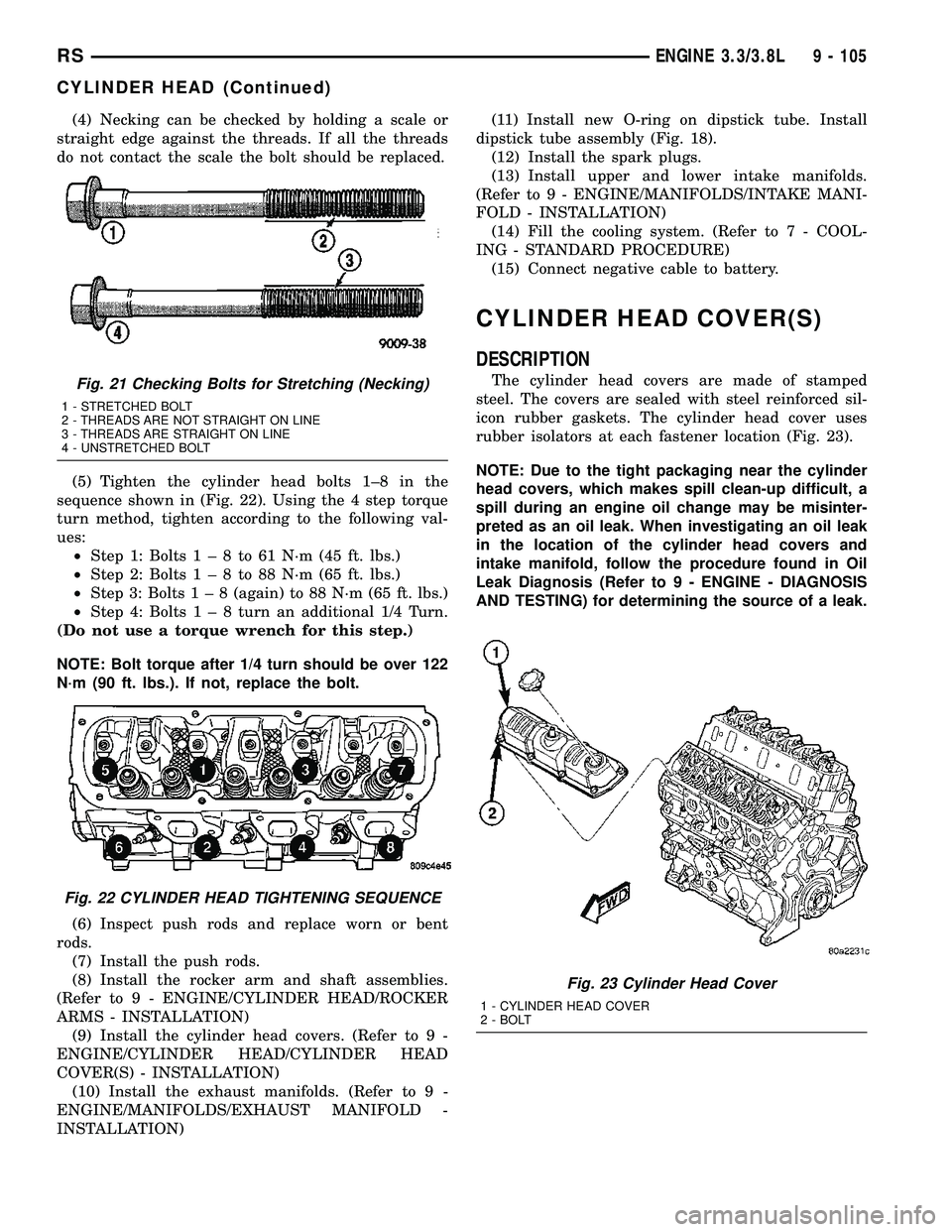
(5) Tighten the cylinder head bolts 1±8 in the
sequence shown in (Fig. 22). Using the 4 step torque
turn method, tighten according to the following val-
ues:
²Step 1: Bolts1±8to61N´m(45ft.lbs.)
²Step 2: Bolts1±8to88N´m(65ft.lbs.)
²Step 3: Bolts1±8(again) to 88 N´m (65 ft. lbs.)
²Step 4: Bolts1±8turn an additional 1/4 Turn.
(Do not use a torque wrench for this step.)
NOTE: Bolt torque after 1/4 turn should be over 122
N´m (90 ft. lbs.). If not, replace the bolt.
(6) Inspect push rods and replace worn or bent
rods.
(7) Install the push rods.
(8) Install the rocker arm and shaft assemblies.
(Refer to 9 - ENGINE/CYLINDER HEAD/ROCKER
ARMS - INSTALLATION)
(9) Install the cylinder head covers. (Refer to 9 -
ENGINE/CYLINDER HEAD/CYLINDER HEAD
COVER(S) - INSTALLATION)
(10) Install the exhaust manifolds. (Refer to 9 -
ENGINE/MANIFOLDS/EXHAUST MANIFOLD -
INSTALLATION)(11) Install new O-ring on dipstick tube. Install
dipstick tube assembly (Fig. 18).
(12) Install the spark plugs.
(13) Install upper and lower intake manifolds.
(Refer to 9 - ENGINE/MANIFOLDS/INTAKE MANI-
FOLD - INSTALLATION)
(14) Fill the cooling system. (Refer to 7 - COOL-
ING - STANDARD PROCEDURE)
(15) Connect negative cable to battery.
CYLINDER HEAD COVER(S)
DESCRIPTION
The cylinder head covers are made of stamped
steel. The covers are sealed with steel reinforced sil-
icon rubber gaskets. The cylinder head cover uses
rubber isolators at each fastener location (Fig. 23).
NOTE: Due to the tight packaging near the cylinder
head covers, which makes spill clean-up difficult, a
spill during an engine oil change may be misinter-
preted as an oil leak. When investigating an oil leak
in the location of the cylinder head covers and
intake manifold, follow the procedure found in Oil
Leak Diagnosis (Refer to 9 - ENGINE - DIAGNOSIS
AND TESTING) for determining the source of a leak.Fig. 21 Checking Bolts for Stretching (Necking)
1 - STRETCHED BOLT
2 - THREADS ARE NOT STRAIGHT ON LINE
3 - THREADS ARE STRAIGHT ON LINE
4 - UNSTRETCHED BOLT
Fig. 22 CYLINDER HEAD TIGHTENING SEQUENCE
Fig. 23 Cylinder Head Cover
1 - CYLINDER HEAD COVER
2 - BOLT
RSENGINE 3.3/3.8L9 - 105
CYLINDER HEAD (Continued)
Page 1283 of 2339
CYLINDER HEAD COVER -
RIGHT
REMOVAL
(1) Disconnect negative cable from battery.
(2) Remove the wiper module. (Refer to 8 - ELEC-
TRICAL/WIPERS/WASHERS/WIPER MODULE -
REMOVAL)
(3) Disconnect spark plug wires from plugs.
(4) Disconnect PCV hose from cylinder head cover
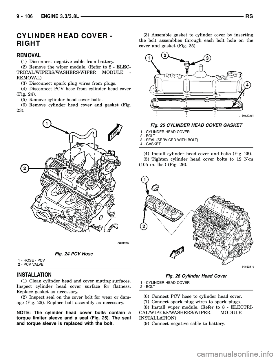
(Fig. 24).
(5) Remove cylinder head cover bolts.
(6) Remove cylinder head cover and gasket (Fig.
23).
INSTALLATION
(1) Clean cylinder head and cover mating surfaces.
Inspect cylinder head cover surface for flatness.
Replace gasket as necessary.
(2) Inspect seal on the cover bolt for wear or dam-
age (Fig. 25). Replace bolt assembly as necessary.
NOTE: The cylinder head cover bolts contain a
torque limiter sleeve and a seal (Fig. 25). The seal
and torque sleeve is replaced with the bolt.(3) Assemble gasket to cylinder cover by inserting
the bolt assemblies through each bolt hole on the
cover and gasket (Fig. 25).
(4) Install cylinder head cover and bolts (Fig. 26).
(5) Tighten cylinder head cover bolts to 12 N´m
(105 in. lbs.) (Fig. 26).
(6) Connect PCV hose to cylinder head cover.
(7) Connect spark plug wires to spark plugs.
(8) Install wiper module. (Refer to 8 - ELECTRI-
CAL/WIPERS/WASHERS/WIPER MODULE -
INSTALLATION)
(9) Connect negative cable to battery.
Fig. 24 PCV Hose
1 - HOSE - PCV
2 - P C V VA LV E
Fig. 25 CYLINDER HEAD COVER GASKET
1 - CYLINDER HEAD COVER
2 - BOLT
3 - SEAL (SERVICED WITH BOLT)
4 - GASKET
Fig. 26 Cylinder Head Cover
1 - CYLINDER HEAD COVER
2 - BOLT
9 - 106 ENGINE 3.3/3.8LRS
Page 1288 of 2339
REMOVAL - CYLINDER HEAD ON
(1) Disconnect negative cable from battery.
(2) Remove spark plug wires and all spark plugs.
(3) Remove cylinder head cover(s). (Refer to 9 -
ENGINE/CYLINDER HEAD/CYLINDER HEAD
COVER(S) - REMOVAL)
(4) Remove rocker arms and shaft. (Refer to 9 -
ENGINE/CYLINDER HEAD/ROCKER ARMS -
REMOVAL)
(5) Rotate engine until the piston in the cylinder
bore requiring spring removal is at TDC.
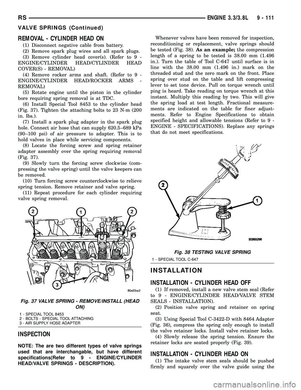
(6) Install Special Tool 8453 to the cylinder head
(Fig. 37). Tighten the attaching bolts to 23 N´m (200
in. lbs.).
(7) Install a spark plug adapter in the spark plug
hole. Connect air hose that can supply 620.5±689 kPa
(90±100 psi) of air pressure to adapter. This is to
hold valves in place while servicing components.
(8) Locate the forcing screw and spring retainer
adapter assembly over the spring requiring removal
(Fig. 37).
(9) Slowly turn the forcing screw clockwise (com-
pressing the valve spring) until the valve keepers can
be removed.
(10) Turn forcing screw counterclockwise to relieve
spring tension. Remove retainer and valve spring.
(11) Repeat procedure for each cylinder requiring
valve spring removal.
INSPECTION
NOTE: The are two different types of valve springs
used that are interchangable, but have different
specifications(Refer to 9 - ENGINE/CYLINDER
HEAD/VALVE SPRINGS - DESCRIPTION).Whenever valves have been removed for inspection,
reconditioning or replacement, valve springs should
be tested (Fig. 38).As an example;the compression
length of a spring to be tested is 38.00 mm (1.496
in.). Turn the table of Tool C-647 until surface is in
line with the 38.00 mm (1.496 in.) mark on the
threaded stud and the zero mark on the front. Place
spring over stud on the table and lift compressing
lever to set tone device. Pull on torque wrench until
ping is heard. Take reading on torque wrench at this
instant. Multiply this reading by two. This will give
the spring load at test length. Fractional measure-
ments are indicated on the table for finer adjust-
ments. Refer to Engine Specifications to obtain
specified height and allowable tensions (Refer to 9 -
ENGINE - SPECIFICATIONS). Replace any springs
that do not meet specifications.
INSTALLATION
INSTALLATION - CYLINDER HEAD OFF
(1) If removed, install a new valve stem seal (Refer
to 9 - ENGINE/CYLINDER HEAD/VALVE STEM
SEALS - INSTALLATION).
(2) Position valve spring and retainer on spring
seat.
(3) Using Special Tool C-3422-D with 8464 Adapter
(Fig. 36), compress the spring only enough to install
the valve retainer locks. Install valve retainer locks.
(4) Slowly release the spring tension. Ensure the
retainer locks are seated properly (Fig. 39).
INSTALLATION - CYLINDER HEAD ON
(1) The intake valve stem seals should be pushed
firmly and squarely over the valve guide using the
Fig. 37 VALVE SPRING - REMOVE/INSTALL (HEAD
ON)
1 - SPECIAL TOOL 8453
2 - BOLTS - SPECIAL TOOL ATTACHING
3 - AIR SUPPLY HOSE ADAPTER
Fig. 38 TESTING VALVE SPRING
1 - SPECIAL TOOL C-647
RSENGINE 3.3/3.8L9 - 111
VALVE SPRINGS (Continued)
Page 1294 of 2339
REMOVAL
(1) Remove the cylinder head(s). (Refer to 9 -
ENGINE/CYLINDER HEAD - REMOVAL)
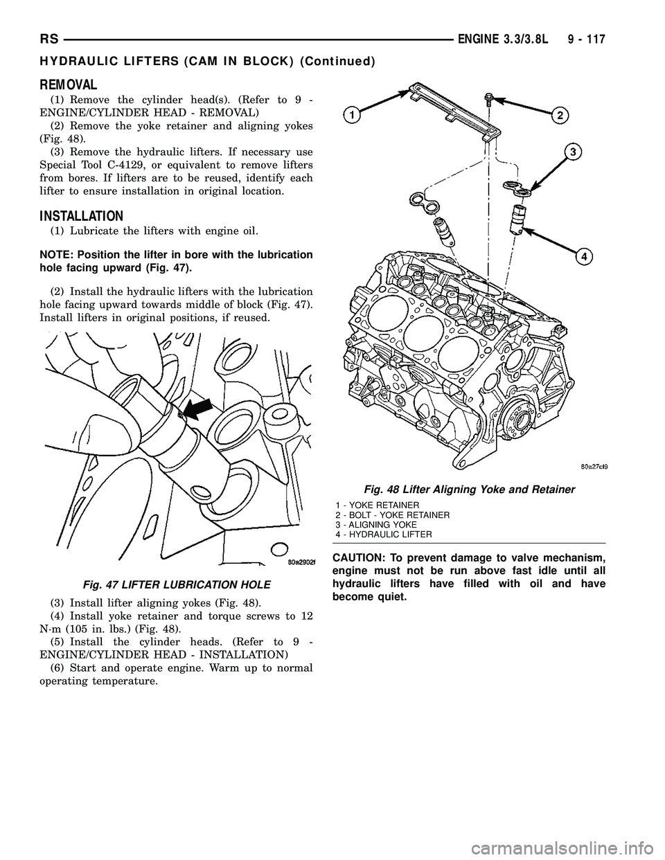
(2) Remove the yoke retainer and aligning yokes
(Fig. 48).
(3) Remove the hydraulic lifters. If necessary use
Special Tool C-4129, or equivalent to remove lifters
from bores. If lifters are to be reused, identify each
lifter to ensure installation in original location.
INSTALLATION
(1) Lubricate the lifters with engine oil.
NOTE: Position the lifter in bore with the lubrication
hole facing upward (Fig. 47).
(2) Install the hydraulic lifters with the lubrication
hole facing upward towards middle of block (Fig. 47).
Install lifters in original positions, if reused.
(3) Install lifter aligning yokes (Fig. 48).
(4) Install yoke retainer and torque screws to 12
N´m (105 in. lbs.) (Fig. 48).
(5) Install the cylinder heads. (Refer to 9 -
ENGINE/CYLINDER HEAD - INSTALLATION)
(6) Start and operate engine. Warm up to normal
operating temperature.CAUTION: To prevent damage to valve mechanism,
engine must not be run above fast idle until all
hydraulic lifters have filled with oil and have
become quiet.
Fig. 47 LIFTER LUBRICATION HOLE
Fig. 48 Lifter Aligning Yoke and Retainer
1 - YOKE RETAINER
2 - BOLT - YOKE RETAINER
3 - ALIGNING YOKE
4 - HYDRAULIC LIFTER
RSENGINE 3.3/3.8L9 - 117
HYDRAULIC LIFTERS (CAM IN BLOCK) (Continued)
Page 1295 of 2339
CAMSHAFT & BEARINGS (IN
BLOCK)
DESCRIPTION
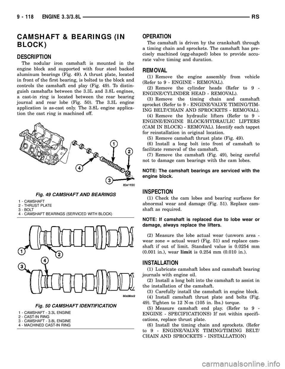
The nodular iron camshaft is mounted in the
engine block and supported with four steel backed
aluminum bearings (Fig. 49). A thrust plate, located
in front of the first bearing, is bolted to the block and
controls the camshaft end play (Fig. 49). To distin-
guish camshafts between the 3.3L and 3.8L engines,
a cast-in ring is located between the rear bearing
journal and rear lobe (Fig. 50). The 3.3L engine
application is as-cast only. The 3.8L engine applica-
tion the cast ring is machined off.
OPERATION
The camshaft is driven by the crankshaft through
a timing chain and sprockets. The camshaft has pre-
cisely machined (egg-shaped) lobes to provide accu-
rate valve timing and duration.
REMOVAL
(1) Remove the engine assembly from vehicle
(Refer to 9 - ENGINE - REMOVAL).
(2) Remove the cylinder heads (Refer to 9 -
ENGINE/CYLINDER HEAD - REMOVAL).
(3) Remove the timing chain and camshaft
sprocket (Refer to 9 - ENGINE/VALVE TIMING/TIM-
ING BELT/CHAIN AND SPROCKETS - REMOVAL).
(4) Remove the hydraulic lifters (Refer to 9 -
ENGINE/ENGINE BLOCK/HYDRAULIC LIFTERS
(CAM IN BLOCK) - REMOVAL). Identify each tappet
for reinstallation in original location.
(5) Remove camshaft thrust plate (Fig. 49).
(6) Install a long bolt into front of camshaft to
facilitate removal of the camshaft.
(7) Remove the camshaft (Fig. 49), being careful
not to damage cam bearings with the cam lobes.
NOTE: The camshaft bearings are serviced with the
engine block.
INSPECTION
(1) Check the cam lobes and bearing surfaces for
abnormal wear and damage (Fig. 51). Replace cam-
shaft as required.
NOTE: If camshaft is replaced due to lobe wear or
damage, always replace the lifters.
(2) Measure the lobe actual wear (unworn area -
wear zone = actual wear) (Fig. 51) and replace cam-
shaft if out of limit. Standard value is 0.0254 mm
(0.001 in.), wearlimitis 0.254 mm (0.010 in.).
INSTALLATION
(1) Lubricate camshaft lobes and camshaft bearing
journals with engine oil.
(2) Install a long bolt into the camshaft to assist in
the installation of the camshaft.
(3) Carefully install the camshaft in engine block.
(4) Install camshaft thrust plate and bolts (Fig.
49). Tighten to 12 N´m (105 in. lbs.) torque.
(5) Measure camshaft end play. (Refer to 9 -
ENGINE - SPECIFICATIONS) If not within specifi-
cations, replace thrust plate.
(6) Install the timing chain and sprockets. (Refer
to 9 - ENGINE/VALVE TIMING/TIMING BELT/
CHAIN AND SPROCKETS - INSTALLATION)
Fig. 49 CAMSHAFT AND BEARINGS
1 - CAMSHAFT
2 - THRUST PLATE
3 - BOLT
4 - CAMSHAFT BEARINGS (SERVICED WITH BLOCK)
Fig. 50 CAMSHAFT IDENTIFICATION
1 - CAMSHAFT - 3.3L ENGINE
2 - CAST-IN RING
3 - CAMSHAFT - 3.8L ENGINE
4 - MACHINED CAST-IN RING
9 - 118 ENGINE 3.3/3.8LRS
Page 1297 of 2339
(1) Before installing the nuts the threads should
be oiled with engine oil.
(2) Install nuts finger tight on each bolt then alter-
nately torque each nut to assemble the cap properly.
(3) Tighten the nuts to 54 N´m PLUS 1/4 turn (40
ft. lbs. PLUS 1/4 turn).
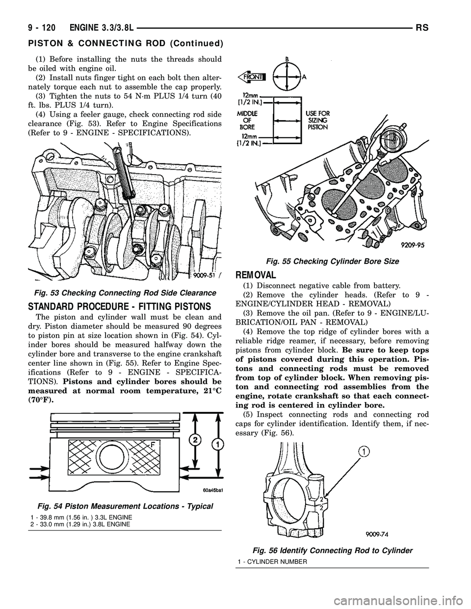
(4) Using a feeler gauge, check connecting rod side
clearance (Fig. 53). Refer to Engine Specifications
(Refer to 9 - ENGINE - SPECIFICATIONS).
STANDARD PROCEDURE - FITTING PISTONS
The piston and cylinder wall must be clean and
dry. Piston diameter should be measured 90 degrees
to piston pin at size location shown in (Fig. 54). Cyl-
inder bores should be measured halfway down the
cylinder bore and transverse to the engine crankshaft
center line shown in (Fig. 55). Refer to Engine Spec-
ifications (Refer to 9 - ENGINE - SPECIFICA-
TIONS).Pistons and cylinder bores should be
measured at normal room temperature, 21ÉC
(70ÉF).
REMOVAL
(1) Disconnect negative cable from battery.
(2) Remove the cylinder heads. (Refer to 9 -
ENGINE/CYLINDER HEAD - REMOVAL)
(3) Remove the oil pan. (Refer to 9 - ENGINE/LU-
BRICATION/OIL PAN - REMOVAL)
(4) Remove the top ridge of cylinder bores with a
reliable ridge reamer, if necessary, before removing
pistons from cylinder block.Be sure to keep tops
of pistons covered during this operation. Pis-
tons and connecting rods must be removed
from top of cylinder block. When removing pis-
ton and connecting rod assemblies from the
engine, rotate crankshaft so that each connect-
ing rod is centered in cylinder bore.
(5) Inspect connecting rods and connecting rod
caps for cylinder identification. Identify them, if nec-
essary (Fig. 56).Fig. 53 Checking Connecting Rod Side Clearance
Fig. 54 Piston Measurement Locations - Typical
1 - 39.8 mm (1.56 in. ) 3.3L ENGINE
2 - 33.0 mm (1.29 in.) 3.8L ENGINE
Fig. 55 Checking Cylinder Bore Size
Fig. 56 Identify Connecting Rod to Cylinder
1 - CYLINDER NUMBER
9 - 120 ENGINE 3.3/3.8LRS
PISTON & CONNECTING ROD (Continued)
Page 1300 of 2339
CONNECTING ROD BEARINGS
STANDARD PROCEDURE - MEASURING
CONNECTING ROD BEARING CLEARANCE
The bearing caps are not interchangeable and
should be marked at removal to ensure correct
assembly. The bearing shells must be installed with
the tangs inserted into the machined grooves in the
rods and caps. Install cap with the tangs on the same
side as the rod. Fit all rods on one bank until com-
plete. Connecting rod bearings are available in the
standard size and the following undersizes: 0.025
mm (0.001 in.) and 0.250 mm (0.010 in.).
CAUTION: Install the bearings in pairs. Do not use a
new bearing half with an old bearing half. Do not
file the rods or bearing caps.
Measure connecting rod journal for taper and out-
of-round. (Refer to 9 - ENGINE/ENGINE BLOCK/
CRANKSHAFT - INSPECTION)The connecting rod bearing clearances can be
determined by use of Plastigage or the equivalent.
The following is the recommended procedure for the
use of Plastigage:
(1) Rotate the crankshaft until the connecting rod
to be checked is at the bottom of its stroke.
(2) Remove oil film from surface to be checked.
Plastigage is soluble in oil.
(3) Place a piece of Plastigage across the entire
width of the bearing shell in the bearing cap approx-
imately 6.35 mm (1/4 in.) off center and away from
the oil hole. In addition, suspect areas can be
checked by placing Plastigage in that area.
(4) Assemble the rod cap with Plastigage in place.
Tighten the rod cap to the specified torque.Do not
rotate the crankshaft while assembling the cap
or the Plastigage may be smeared, giving inac-
curate results.
(5) Remove the bearing cap and compare the
width of the flattened Plastigage with the scale pro-
vided on the package (Fig. 61). Locate the band clos-
est to the same width. This band indicates the
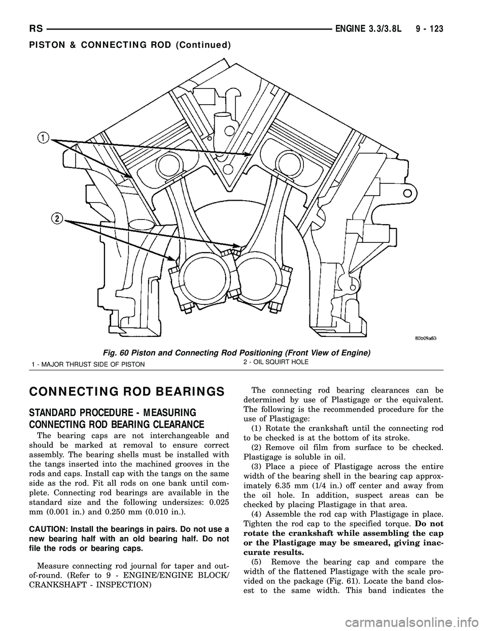
Fig. 60 Piston and Connecting Rod Positioning (Front View of Engine)
1 - MAJOR THRUST SIDE OF PISTON2 - OIL SQUIRT HOLE
RSENGINE 3.3/3.8L9 - 123
PISTON & CONNECTING ROD (Continued)