2005 CHRYSLER VOYAGER oil
[x] Cancel search: oilPage 1270 of 2339
(49) Install the radiator upper support crossmem-
ber (Refer to 23 - BODY/EXTERIOR/GRILLE OPEN-
ING REINFORCEMENT - INSTALLATION).
(50) Install the wiper module (Refer to 8 - ELEC-
TRICAL/WIPERS/WASHERS/WIPER MODULE -
INSTALLATION).
(51) Connect the fuel line to fuel rail (Refer to 14 -
FUEL SYSTEM/FUEL DELIVERY/FUEL LINES -
STANDARD PROCEDURE).
(52) Install the air cleaner and hoses.
(53) Install new oil filter. Fill engine crankcase
with proper oil to correct level.
(54) Connect negative cable to battery.
(55) Fill the cooling system (Refer to 7 - COOLING
- STANDARD PROCEDURE).
(56) Start engine and run until operating temper-
ature is reached.
(57) Adjust transmission linkage, if necessary.
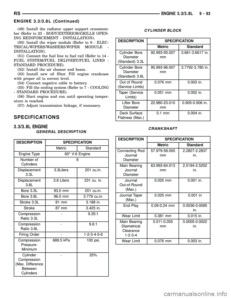
SPECIFICATIONS
3.3/3.8L ENGINE
GENERAL DESCRIPTION
DESCRIPTION SPECIFICATION
Metric Standard
Engine Type 60É V-6 Engine
Number of
Cylinders6
Displacement
3.3L3.3Liters 201 cu.in.
Displacement
3.8L3.8 Liters 231 cu. in.
Bore 3.3L 93.0 mm 201 cu.in.
Bore 3.8L 96.0 mm 3.779 cu.in.
Stroke 3.3L 81 mm 3.188 in.
Stroke 87 mm 3.425 in.
Compression
Ratio 3.3L- 9.35:1
Compression
Ratio 3.8L- 9.6:1
Firing Order - 1-2-3-4-5-6
Compression
Pressure-
Minimum689.5 kPa 100 psi.
Cylinder
Compression
(Max. Difference
Between
Cylinders- 25%
CYLINDER BLOCK
DESCRIPTION SPECIFICATION
Metric Standard
Cylinder Bore
Diameter
(Standard) 3.3L92.993-93.007
mm3.661-3.6617 in.
Cylinder Bore
Diameter
(Standard) 3.8L95.993-96.007
mm3.7792-3.780 in.
Out of Round
(Service Limits)0.076 mm 0.003 in.
Taper (Service
Limits)0.051 mm 0.002 in.
Lifter Bore
Diameter22.980-23.010
mm0.905-0.906 in.
Deck Surface
Flatness (Max.)0.1 mm 0.004 in.
CRANKSHAFT
DESCRIPTION SPECIFICATION
Metric Standard
Connecting Rod
Journal
Diameter57.979-58.005
mm2.2827-2.2837
in.
Main Bearing
Journal
Diameter63.993-64.013
mm2.5194-2.5202
in.
Journal
Out-of-Round
(Max.)0.025 mm 0.001 in.
Journal Taper
(Max.)0.025 mm 0.001 in
End Play 0.09-0.24 mm 0.0036-0.0095
in.
Wear Limit 0.381 mm 0.015 in.
Main Bearing
Diametrical
Clearance
1-2-3-40.011-0.055
mm0.0005-0.0022
in.
Wear Limit 0.076 mm 0.003 in.
RSENGINE 3.3/3.8L9-93
ENGINE 3.3/3.8L (Continued)
Page 1271 of 2339
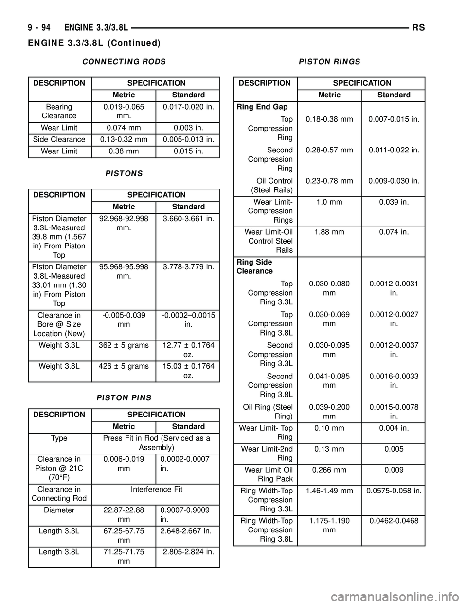
CONNECTING RODS
DESCRIPTION SPECIFICATION
Metric Standard
Bearing
Clearance0.019-0.065
mm.0.017-0.020 in.
Wear Limit 0.074 mm 0.003 in.
Side Clearance 0.13-0.32 mm 0.005-0.013 in.
Wear Limit 0.38 mm 0.015 in.
PISTONS
DESCRIPTION SPECIFICATION
Metric Standard
Piston Diameter
3.3L-Measured
39.8 mm (1.567
in) From Piston
To p92.968-92.998
mm.3.660-3.661 in.
Piston Diameter
3.8L-Measured
33.01 mm (1.30
in) From Piston
To p95.968-95.998
mm.3.778-3.779 in.
Clearance in
Bore @ Size
Location (New)-0.005-0.039
mm-0.0002±0.0015
in.
Weight 3.3L 362 5 grams 12.77 0.1764
oz.
Weight 3.8L 426 5 grams 15.03 0.1764
oz.
PISTON PINS
DESCRIPTION SPECIFICATION
Metric Standard
Type Press Fit in Rod (Serviced as a
Assembly)
Clearance in
Piston @ 21C
(70ÉF)0.006-0.019
mm0.0002-0.0007
in.
Clearance in
Connecting RodInterference Fit
Diameter 22.87-22.88
mm0.9007-0.9009
in.
Length 3.3L 67.25-67.75
mm2.648-2.667 in.
Length 3.8L 71.25-71.75
mm2.805-2.824 in.
PISTON RINGS
DESCRIPTION SPECIFICATION
Metric Standard
Ring End Gap
To p
Compression
Ring0.18-0.38 mm 0.007-0.015 in.
Second
Compression
Ring0.28-0.57 mm 0.011-0.022 in.
Oil Control
(Steel Rails)0.23-0.78 mm 0.009-0.030 in.
Wear Limit-
Compression
Rings1.0 mm 0.039 in.
Wear Limit-Oil
Control Steel
Rails1.88 mm 0.074 in.
Ring Side
Clearance
To p
Compression
Ring 3.3L0.030-0.080
mm0.0012-0.0031
in.
To p
Compression
Ring 3.8L0.030-0.069
mm0.0012-0.0027
in.
Second
Compression
Ring 3.3L0.030-0.095
mm0.0012-0.0037
in.
Second
Compression
Ring 3.8L0.041-0.085
mm0.0016-0.0033
in.
Oil Ring (Steel
Ring)0.039-0.200
mm0.0015-0.0078
in.
Wear Limit- Top
Ring0.10 mm 0.004 in.
Wear Limit-2nd
Ring0.13 mm 0.005
Wear Limit Oil
Ring Pack0.266 mm 0.009
Ring Width-Top
Compression
Ring 3.3L1.46-1.49 mm 0.0575-0.058 in.
Ring Width-Top
Compression
Ring 3.8L1.175-1.190
mm0.0462-0.0468
9 - 94 ENGINE 3.3/3.8LRS
ENGINE 3.3/3.8L (Continued)
Page 1272 of 2339
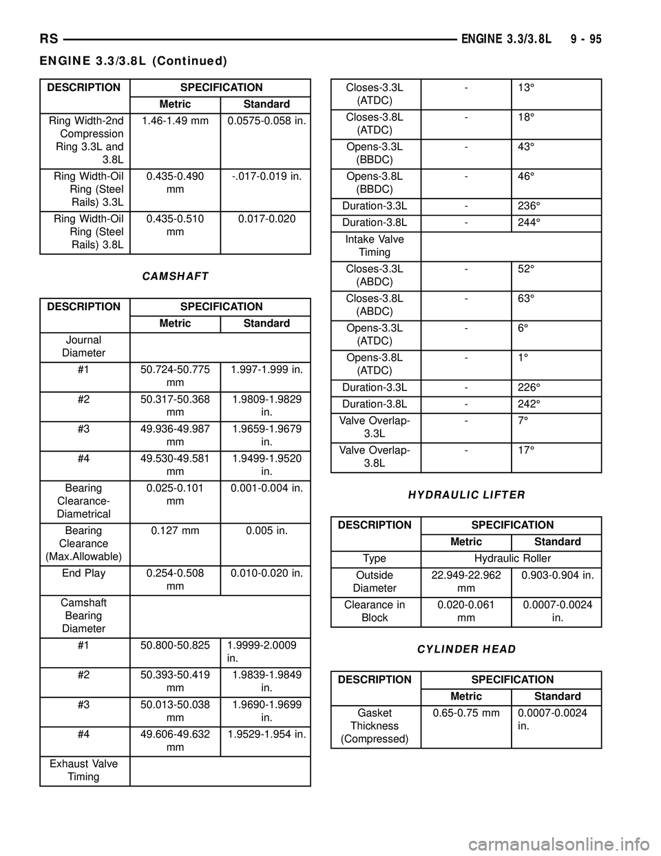
DESCRIPTION SPECIFICATION
Metric Standard
Ring Width-2nd
Compression
Ring 3.3L and
3.8L1.46-1.49 mm 0.0575-0.058 in.
Ring Width-Oil
Ring (Steel
Rails) 3.3L0.435-0.490
mm-.017-0.019 in.
Ring Width-Oil
Ring (Steel
Rails) 3.8L0.435-0.510
mm0.017-0.020
CAMSHAFT
DESCRIPTION SPECIFICATION
Metric Standard
Journal
Diameter
#1 50.724-50.775
mm1.997-1.999 in.
#2 50.317-50.368
mm1.9809-1.9829
in.
#3 49.936-49.987
mm1.9659-1.9679
in.
#4 49.530-49.581
mm1.9499-1.9520
in.
Bearing
Clearance-
Diametrical0.025-0.101
mm0.001-0.004 in.
Bearing
Clearance
(Max.Allowable)0.127 mm 0.005 in.
End Play 0.254-0.508
mm0.010-0.020 in.
Camshaft
Bearing
Diameter
#1 50.800-50.825 1.9999-2.0009
in.
#2 50.393-50.419
mm1.9839-1.9849
in.
#3 50.013-50.038
mm1.9690-1.9699
in.
#4 49.606-49.632
mm1.9529-1.954 in.
Exhaust Valve
Timing
Closes-3.3L
(ATDC)- 13É
Closes-3.8L
(ATDC)- 18É
Opens-3.3L
(BBDC)- 43É
Opens-3.8L
(BBDC)- 46É
Duration-3.3L - 236É
Duration-3.8L - 244É
Intake Valve
Timing
Closes-3.3L
(ABDC)- 52É
Closes-3.8L
(ABDC)- 63É
Opens-3.3L
(ATDC)-6É
Opens-3.8L
(ATDC)-1É
Duration-3.3L - 226É
Duration-3.8L - 242É
Valve Overlap-
3.3L-7É
Valve Overlap-
3.8L- 17É
HYDRAULIC LIFTER
DESCRIPTION SPECIFICATION
Metric Standard
Type Hydraulic Roller
Outside
Diameter22.949-22.962
mm0.903-0.904 in.
Clearance in
Block0.020-0.061
mm0.0007-0.0024
in.
CYLINDER HEAD
DESCRIPTION SPECIFICATION
Metric Standard
Gasket
Thickness
(Compressed)0.65-0.75 mm 0.0007-0.0024
in.
RSENGINE 3.3/3.8L9-95
ENGINE 3.3/3.8L (Continued)
Page 1274 of 2339
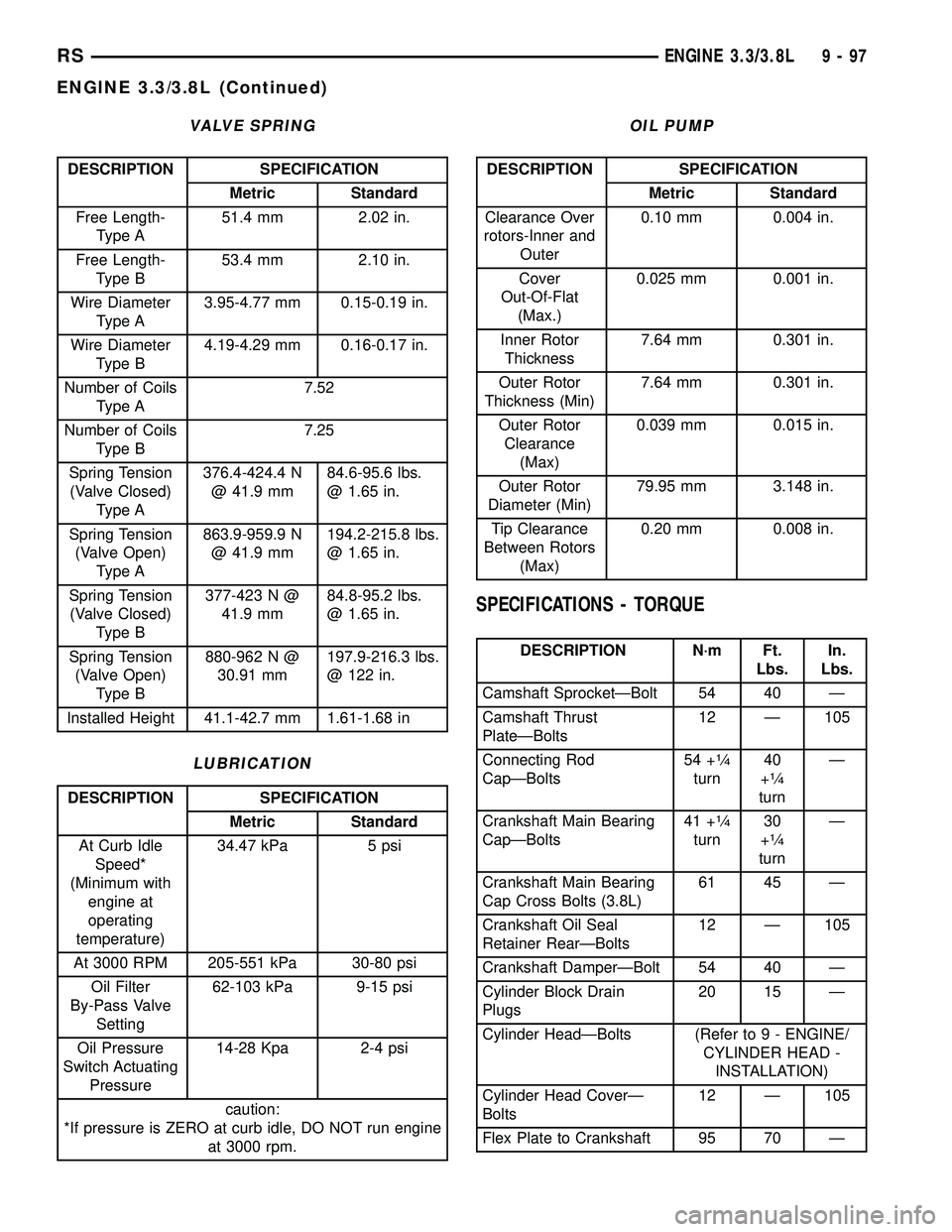
VALVE SPRING
DESCRIPTION SPECIFICATION
Metric Standard
Free Length-
Type A51.4 mm 2.02 in.
Free Length-
Type B53.4 mm 2.10 in.
Wire Diameter
Type A3.95-4.77 mm 0.15-0.19 in.
Wire Diameter
Type B4.19-4.29 mm 0.16-0.17 in.
Number of Coils
Type A7.52
Number of Coils
Type B7.25
Spring Tension
(Valve Closed)
Type A376.4-424.4 N
@ 41.9 mm84.6-95.6 lbs.
@ 1.65 in.
Spring Tension
(Valve Open)
Type A863.9-959.9 N
@ 41.9 mm194.2-215.8 lbs.
@ 1.65 in.
Spring Tension
(Valve Closed)
Type B377-423 N @
41.9 mm84.8-95.2 lbs.
@ 1.65 in.
Spring Tension
(Valve Open)
Type B880-962 N @
30.91 mm197.9-216.3 lbs.
@ 122 in.
Installed Height 41.1-42.7 mm 1.61-1.68 in
LUBRICATION
DESCRIPTION SPECIFICATION
Metric Standard
At Curb Idle
Speed*
(Minimum with
engine at
operating
temperature)34.47 kPa 5 psi
At 3000 RPM 205-551 kPa 30-80 psi
Oil Filter
By-Pass Valve
Setting62-103 kPa 9-15 psi
Oil Pressure
Switch Actuating
Pressure14-28 Kpa 2-4 psi
caution:
*If pressure is ZERO at curb idle, DO NOT run engine
at 3000 rpm.
OIL PUMP
DESCRIPTION SPECIFICATION
Metric Standard
Clearance Over
rotors-Inner and
Outer0.10 mm 0.004 in.
Cover
Out-Of-Flat
(Max.)0.025 mm 0.001 in.
Inner Rotor
Thickness7.64 mm 0.301 in.
Outer Rotor
Thickness (Min)7.64 mm 0.301 in.
Outer Rotor
Clearance
(Max)0.039 mm 0.015 in.
Outer Rotor
Diameter (Min)79.95 mm 3.148 in.
Tip Clearance
Between Rotors
(Max)0.20 mm 0.008 in.
SPECIFICATIONS - TORQUE
DESCRIPTION N´m Ft.
Lbs.In.
Lbs.
Camshaft SprocketÐBolt 54 40 Ð
Camshaft Thrust
PlateÐBolts12 Ð 105
Connecting Rod
CapÐBolts54 +
1¤4
turn40
+1¤4
turnÐ
Crankshaft Main Bearing
CapÐBolts41 +
1¤4
turn30
+1¤4
turnÐ
Crankshaft Main Bearing
Cap Cross Bolts (3.8L)61 45 Ð
Crankshaft Oil Seal
Retainer RearÐBolts12 Ð 105
Crankshaft DamperÐBolt 54 40 Ð
Cylinder Block Drain
Plugs20 15 Ð
Cylinder HeadÐBolts (Refer to 9 - ENGINE/
CYLINDER HEAD -
INSTALLATION)
Cylinder Head CoverÐ
Bolts12 Ð 105
Flex Plate to Crankshaft 95 70 Ð
RSENGINE 3.3/3.8L9-97
ENGINE 3.3/3.8L (Continued)
Page 1275 of 2339
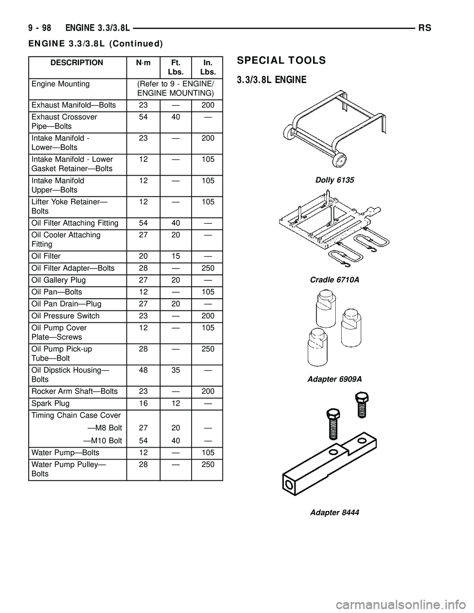
DESCRIPTION N´m Ft.
Lbs.In.
Lbs.
Engine Mounting (Refer to 9 - ENGINE/
ENGINE MOUNTING)
Exhaust ManifoldÐBolts 23 Ð 200
Exhaust Crossover
PipeÐBolts54 40 Ð
Intake Manifold -
LowerÐBolts23 Ð 200
Intake Manifold - Lower
Gasket RetainerÐBolts12 Ð 105
Intake Manifold
UpperÐBolts12 Ð 105
Lifter Yoke RetainerÐ
Bolts12 Ð 105
Oil Filter Attaching Fitting 54 40 Ð
Oil Cooler Attaching
Fitting27 20 Ð
Oil Filter 20 15 Ð
Oil Filter AdapterÐBolts 28 Ð 250
Oil Gallery Plug 27 20 Ð
Oil PanÐBolts 12 Ð 105
Oil Pan DrainÐPlug 27 20 Ð
Oil Pressure Switch 23 Ð 200
Oil Pump Cover
PlateÐScrews12 Ð 105
Oil Pump Pick-up
TubeÐBolt28 Ð 250
Oil Dipstick HousingÐ
Bolts48 35 Ð
Rocker Arm ShaftÐBolts 23 Ð 200
Spark Plug 16 12 Ð
Timing Chain Case Cover
ÐM8 Bolt 27 20 Ð
ÐM10 Bolt 54 40 Ð
Water PumpÐBolts 12 Ð 105
Water Pump PulleyÐ
Bolts28 Ð 250SPECIAL TOOLS
3.3/3.8L ENGINE
Dolly 6135
Cradle 6710A
Adapter 6909A
Adapter 8444
9 - 98 ENGINE 3.3/3.8LRS
ENGINE 3.3/3.8L (Continued)
Page 1277 of 2339
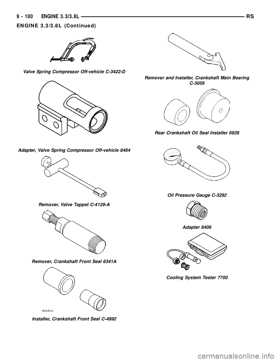
Valve Spring Compressor Off-vehicle C-3422-D
Adapter, Valve Spring Compressor Off-vehicle 8464
Remover, Valve Tappet C-4129-A
Remover, Crankshaft Front Seal 6341A
Installer, Crankshaft Front Seal C-4992
Remover and Installer, Crankshaft Main Bearing
C-3059
Rear Crankshaft Oil Seal Installer 6926
Oil Pressure Gauge C-3292
Adapter 8406
Cooling System Tester 7700
9 - 100 ENGINE 3.3/3.8LRS
ENGINE 3.3/3.8L (Continued)
Page 1281 of 2339
Remove all gasket material from cylinder head and
block (Refer to 9 - ENGINE - STANDARD PROCE-
DURE). Be careful not to gouge or scratch the alumi-
num head sealing surface.
Clean all engine oil passages.
INSPECTION
(1) Before cleaning, check for leaks, damage and
cracks.
(2) Clean cylinder head and oil passages.
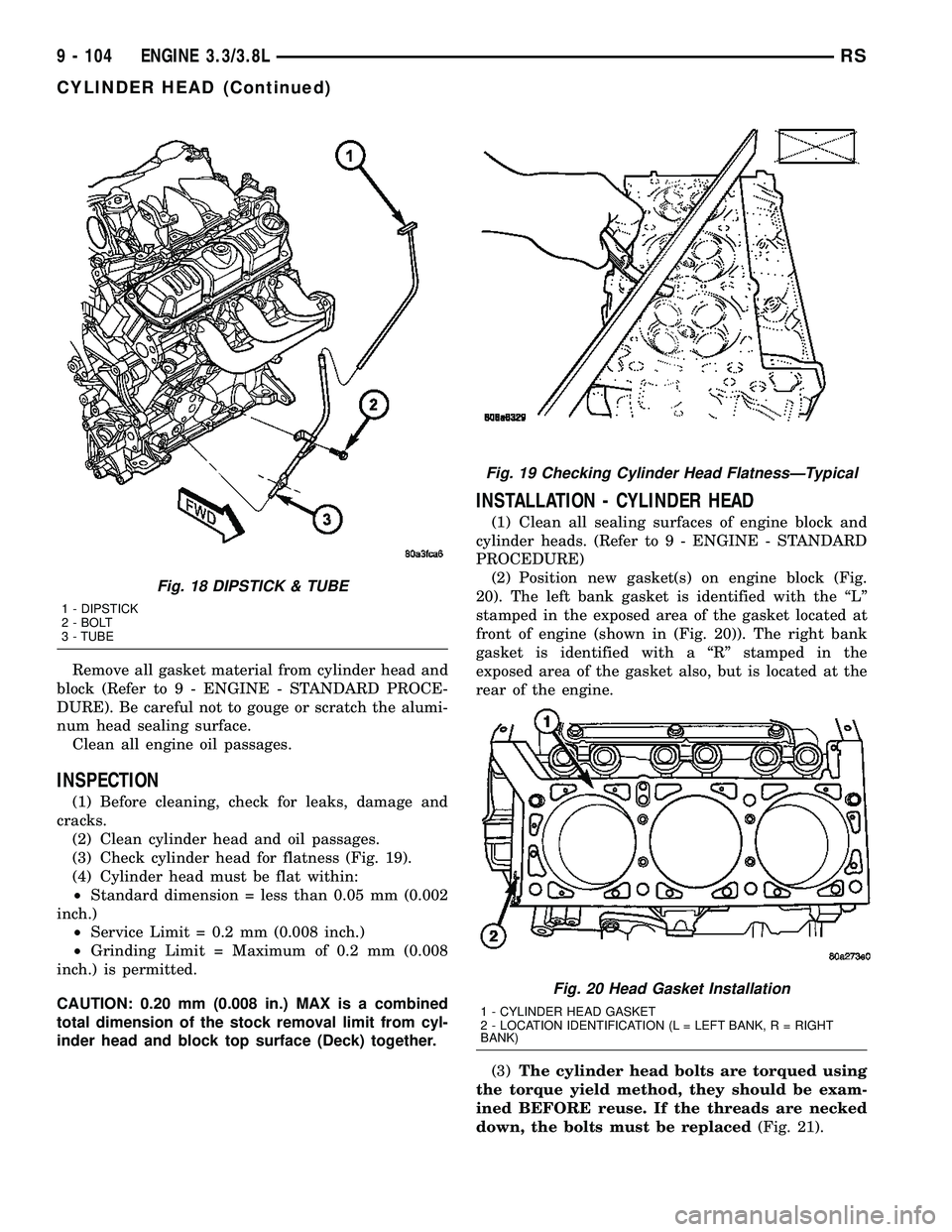
(3) Check cylinder head for flatness (Fig. 19).
(4) Cylinder head must be flat within:
²Standard dimension = less than 0.05 mm (0.002
inch.)
²Service Limit = 0.2 mm (0.008 inch.)
²Grinding Limit = Maximum of 0.2 mm (0.008
inch.) is permitted.
CAUTION: 0.20 mm (0.008 in.) MAX is a combined
total dimension of the stock removal limit from cyl-
inder head and block top surface (Deck) together.
INSTALLATION - CYLINDER HEAD
(1) Clean all sealing surfaces of engine block and
cylinder heads. (Refer to 9 - ENGINE - STANDARD
PROCEDURE)
(2) Position new gasket(s) on engine block (Fig.
20). The left bank gasket is identified with the ªLº
stamped in the exposed area of the gasket located at
front of engine (shown in (Fig. 20)). The right bank
gasket is identified with a ªRº stamped in the
exposed area of the gasket also, but is located at the
rear of the engine.
(3)The cylinder head bolts are torqued using
the torque yield method, they should be exam-
ined BEFORE reuse. If the threads are necked
down, the bolts must be replaced(Fig. 21).
Fig. 18 DIPSTICK & TUBE
1 - DIPSTICK
2 - BOLT
3 - TUBE
Fig. 19 Checking Cylinder Head FlatnessÐTypical
Fig. 20 Head Gasket Installation
1 - CYLINDER HEAD GASKET
2 - LOCATION IDENTIFICATION (L = LEFT BANK, R = RIGHT
BANK)
9 - 104 ENGINE 3.3/3.8LRS
CYLINDER HEAD (Continued)
Page 1282 of 2339
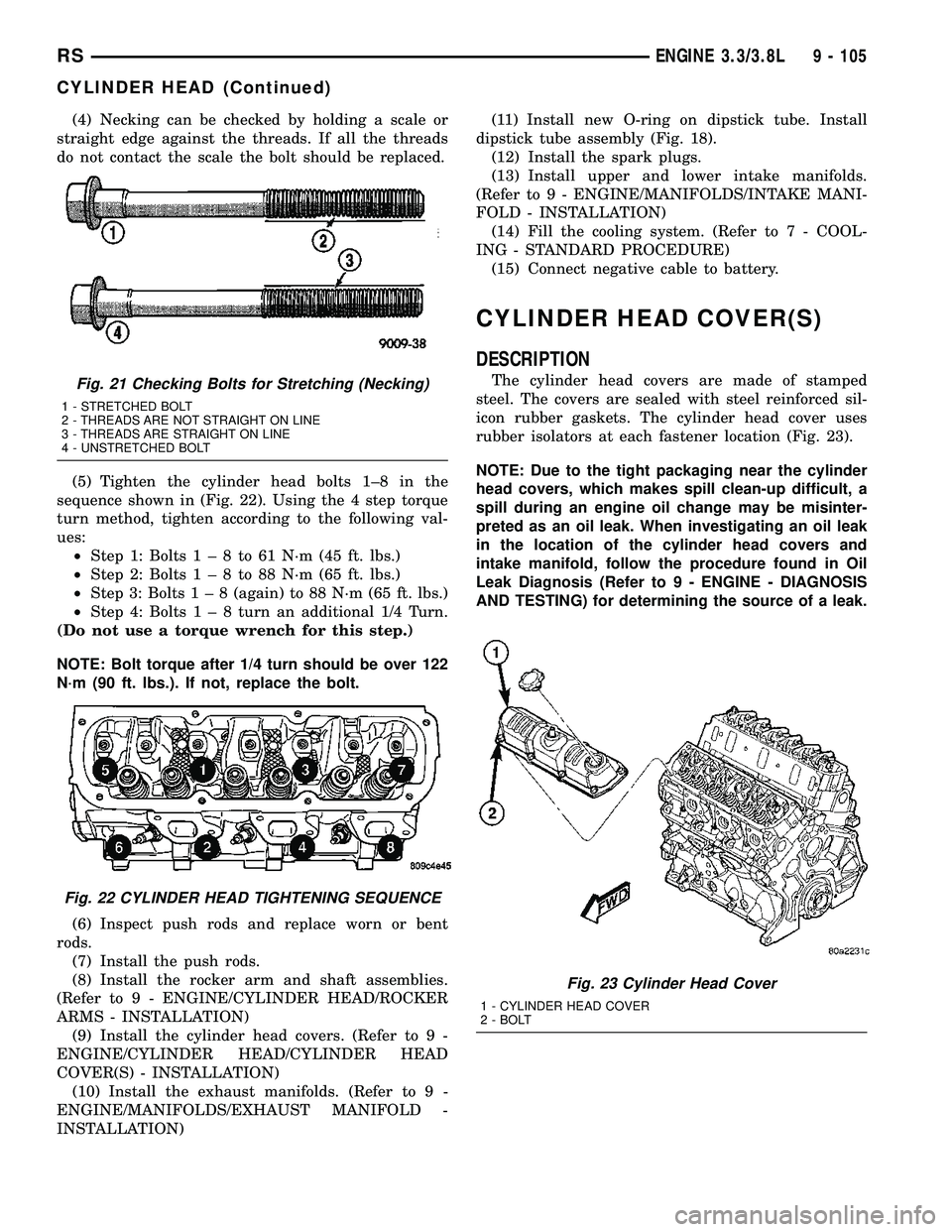
(4) Necking can be checked by holding a scale or
straight edge against the threads. If all the threads
do not contact the scale the bolt should be replaced.
(5) Tighten the cylinder head bolts 1±8 in the
sequence shown in (Fig. 22). Using the 4 step torque
turn method, tighten according to the following val-
ues:
²Step 1: Bolts1±8to61N´m(45ft.lbs.)
²Step 2: Bolts1±8to88N´m(65ft.lbs.)
²Step 3: Bolts1±8(again) to 88 N´m (65 ft. lbs.)
²Step 4: Bolts1±8turn an additional 1/4 Turn.
(Do not use a torque wrench for this step.)
NOTE: Bolt torque after 1/4 turn should be over 122
N´m (90 ft. lbs.). If not, replace the bolt.
(6) Inspect push rods and replace worn or bent
rods.
(7) Install the push rods.
(8) Install the rocker arm and shaft assemblies.
(Refer to 9 - ENGINE/CYLINDER HEAD/ROCKER
ARMS - INSTALLATION)
(9) Install the cylinder head covers. (Refer to 9 -
ENGINE/CYLINDER HEAD/CYLINDER HEAD
COVER(S) - INSTALLATION)
(10) Install the exhaust manifolds. (Refer to 9 -
ENGINE/MANIFOLDS/EXHAUST MANIFOLD -
INSTALLATION)(11) Install new O-ring on dipstick tube. Install
dipstick tube assembly (Fig. 18).
(12) Install the spark plugs.
(13) Install upper and lower intake manifolds.
(Refer to 9 - ENGINE/MANIFOLDS/INTAKE MANI-
FOLD - INSTALLATION)
(14) Fill the cooling system. (Refer to 7 - COOL-
ING - STANDARD PROCEDURE)
(15) Connect negative cable to battery.
CYLINDER HEAD COVER(S)
DESCRIPTION
The cylinder head covers are made of stamped
steel. The covers are sealed with steel reinforced sil-
icon rubber gaskets. The cylinder head cover uses
rubber isolators at each fastener location (Fig. 23).
NOTE: Due to the tight packaging near the cylinder
head covers, which makes spill clean-up difficult, a
spill during an engine oil change may be misinter-
preted as an oil leak. When investigating an oil leak
in the location of the cylinder head covers and
intake manifold, follow the procedure found in Oil
Leak Diagnosis (Refer to 9 - ENGINE - DIAGNOSIS
AND TESTING) for determining the source of a leak.Fig. 21 Checking Bolts for Stretching (Necking)
1 - STRETCHED BOLT
2 - THREADS ARE NOT STRAIGHT ON LINE
3 - THREADS ARE STRAIGHT ON LINE
4 - UNSTRETCHED BOLT
Fig. 22 CYLINDER HEAD TIGHTENING SEQUENCE
Fig. 23 Cylinder Head Cover
1 - CYLINDER HEAD COVER
2 - BOLT
RSENGINE 3.3/3.8L9 - 105
CYLINDER HEAD (Continued)