Page 1125 of 2339

CONNECTOR NAME/NUMBER COLOR LOCATION FIG.
Right Sliding Door Motor BK At Sliding Door 45
Right Speed Control Switch WT At Steering Wheel N/S
Right Turn Signal Lamp (Export) OR At Lamp N/S
Right Visor/Vanity Lamp BK At Lamp N/S
Sentry Key Remote Entry Module
(SKREEM)BK At Steering Column 20, 21, 22, 23, 31
Siren (United Kingdom) BK Left Front Body N/S
Speed Control Servo (Gas) BK Near Controller Antilock Brake 11, 17, 18
Sunroof Module (Except Export) BK At Sunroof N/S
Sunroof Switch (Except Export) NAT Near Overhead Console N/S
Thatcham Alarm Module (United
Kingdom)BK Top Right Side of Instrument Panel
Near SpeakerN/S
Throttle Position Sensor (Gas) GY On Throttle Body 10, 11, 17
Traction Control Switch BK Rear of Swtich 21, 22, 31
Trailer Tow Connector (Except
Export)Left Quarter Panel N/S
Transmission Control Relay
(Diesel)Near Transmission 16
Transmission Range Sensor DKGY Top of Transmission 14, 19
Transmission Solenoid/Pressure
Switch AssemblyBK Side of Transmission 14, 19
Vehicle Speed Sensor (MTX) BK Rear of Transmission 16
Washer Fluid Level Switch BK Bottom of Reservoir 3
Washer Pump Motor BK Right Fender Well 3
Water in Fuel Sensor (Diesel) BK Left Rear Engine Compartment N/S
Wiper Module DKGY Left Side Cowl 6
GROUNDS
GROUND NUMBER LOCATION FIG.
G100 Body Ground Near Powertrain Control Module N/S
G101 Above Starter 13, 15, 18
G102 Left Headlamp Area 1
G103 Above Starter 15
G200 Left Side of Instrument Panel 20, 21 29
G201 Right Side of Instrument Panel 20, 24, 29
G202 Near Radio N/S
G300 Left B Pillar 32
G301 Right B Pillar 33, 39
G302 Left Rear Quarter 47
G303 Liftgate Ground 49
8W - 91 - 12 8W-91 CONNECTOR/GROUND/SPLICE LOCATIONRS
CONNECTOR/GROUND/SPLICE LOCATION (Continued)
Page 1128 of 2339

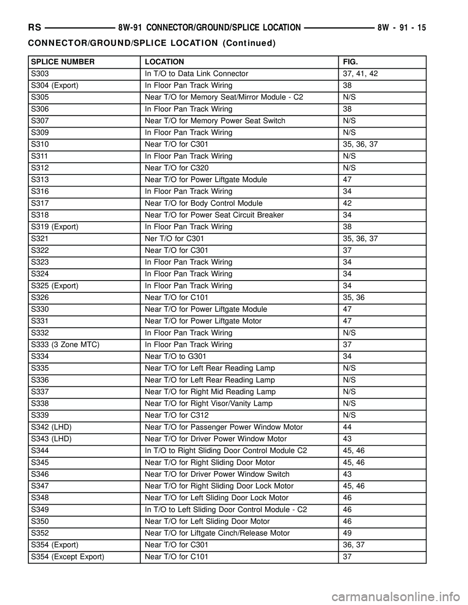
SPLICE NUMBER LOCATION FIG.
S303 In T/O to Data Link Connector 37, 41, 42
S304 (Export) In Floor Pan Track Wiring 38
S305 Near T/O for Memory Seat/Mirror Module - C2 N/S
S306 In Floor Pan Track Wiring 38
S307 Near T/O for Memory Power Seat Switch N/S
S309 In Floor Pan Track Wiring N/S
S310 Near T/O for C301 35, 36, 37
S311 In Floor Pan Track Wiring N/S
S312 Near T/O for C320 N/S
S313 Near T/O for Power Liftgate Module 47
S316 In Floor Pan Track Wiring 34
S317 Near T/O for Body Control Module 42
S318 Near T/O for Power Seat Circuit Breaker 34
S319 (Export) In Floor Pan Track Wiring 38
S321 Ner T/O for C301 35, 36, 37
S322 Near T/O for C301 37
S323 In Floor Pan Track Wiring 34
S324 In Floor Pan Track Wiring 34
S325 (Export) In Floor Pan Track Wiring 34
S326 Near T/O for C101 35, 36
S330 Near T/O for Power Liftgate Module 47
S331 Near T/O for Power Liftgate Motor 47
S332 In Floor Pan Track Wiring N/S
S333 (3 Zone MTC) In Floor Pan Track Wiring 37
S334 Near T/O to G301 34
S335 Near T/O for Left Rear Reading Lamp N/S
S336 Near T/O for Left Rear Reading Lamp N/S
S337 Near T/O for Right Mid Reading Lamp N/S
S338 Near T/O for Right Visor/Vanity Lamp N/S
S339 Near T/O for C312 N/S
S342 (LHD) Near T/O for Passenger Power Window Motor 44
S343 (LHD) Near T/O for Driver Power Window Motor 43
S344 In T/O to Right Sliding Door Control Module C2 45, 46
S345 Near T/O for Right Sliding Door Motor 45, 46
S346 Near T/O for Driver Power Window Switch 43
S347 Near T/O for Right Sliding Door Lock Motor 45, 46
S348 Near T/O for Left Sliding Door Lock Motor 46
S349 In T/O to Left Sliding Door Control Module - C2 46
S350 Near T/O for Left Sliding Door Motor 46
S352 Near T/O for Liftgate Cinch/Release Motor 49
S354 (Export) Near T/O for C301 36, 37
S354 (Except Export) Near T/O for C101 37
RS8W-91 CONNECTOR/GROUND/SPLICE LOCATION8W-91-15
CONNECTOR/GROUND/SPLICE LOCATION (Continued)
Page 1167 of 2339
Fig. 43 DRIVER DOOR
Fig. 44 PASSENGER DOOR
8W - 91 - 54 8W-91 CONNECTOR/GROUND/SPLICE LOCATIONRS
CONNECTOR/GROUND/SPLICE LOCATION (Continued)
Page 1168 of 2339
Fig. 45 RIGHT SLIDING DOOR
RS8W-91 CONNECTOR/GROUND/SPLICE LOCATION8W-91-55
CONNECTOR/GROUND/SPLICE LOCATION (Continued)
Page 1169 of 2339
Fig. 46 LIFTGATE AND SLIDING DOOR MODULES
8W - 91 - 56 8W-91 CONNECTOR/GROUND/SPLICE LOCATIONRS
CONNECTOR/GROUND/SPLICE LOCATION (Continued)
Page 1177 of 2339

(2) Check for battery voltage at the fused B(+) fuse
in the IPM. If OK, go to Step 3. If not OK, repair the
open fused B(+) circuit to the IPM fuse as required.
(3) Open the power outlet door. Check for continu-
ity between the inside circumference of the power
outlet receptacle and a good ground. There should be
continuity. If OK, go to Step 4. If not OK, go to Step
5.
(4) Check for battery voltage at the insulated con-
tact located at the back of the power outlet recepta-
cle. If not OK, go to Step 5.
(5) Disconnect and isolate the battery negative
cable. Remove the appropriate bezel. Check for conti-
nuity between the ground circuit cavity of the power
outlet wire harness connector and a good ground.
There should be continuity. If OK, go to Step 6. If not
OK, repair the open ground circuit to ground as
required.
(6) Connect the battery negative cable. Check for
battery voltage at the fused B(+) circuit cavity of the
power outlet wire harness connector. If OK, replace
the faulty power outlet receptacle. If not OK, repair
the open fused B(+) circuit to the IPM fuse as
required.
REMOVAL
(1) Disconnect and isolate the battery negative
cable.
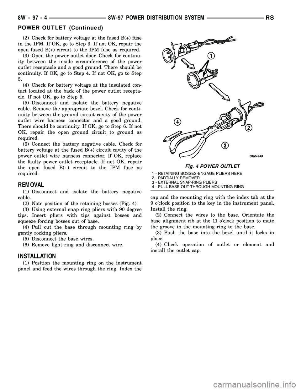
(2) Note position of the retaining bosses (Fig. 4).
(3) Using external snap ring pliers with 90 degree
tips. Insert pliers with tips against bosses and
squeeze forcing bosses out of base.
(4) Pull out the base through mounting ring by
gently rocking pliers.
(5) Disconnect the base wires.
(6) Remove light ring and disconnect wire.
INSTALLATION
(1) Position the mounting ring on the instrument
panel and feed the wires through the ring. Index thecap and the mounting ring with the index tab at the
9 o'clock position to the key in the instrument panel.
Install the ring.
(2) Connect the wires to the base. Orientate the
base alignment rib at the 11 o'clock position to mate
the groove in the mounting ring to the base.
(3) Push the base into the bezel until it locks in
place.
(4) Check operation of outlet or element and
install the outlet cap.
Fig. 4 POWER OUTLET
1 - RETAINING BOSSES-ENGAGE PLIERS HERE
2 - PARTIALLY REMOVED
3 - EXTERNAL SNAP-RING PLIERS
4 - PULL BASE OUT-THROUGH MOUNTING RING
8W - 97 - 4 8W-97 POWER DISTRIBUTION SYSTEMRS
POWER OUTLET (Continued)
Page 1368 of 2339

(6) Open fuel fill door and remove screws mount-
ing fuel filler tube assembly to body. Do not discon-
nect rubber fuel fill or vent hoses from tank at this
time.
(7) Place a transmission jack under center of fuel
tank. Apply a slight amount of pressure to fuel tank
with transmission jack.
(8) Remove fuel tank mounting straps.
(9)Lower the tank just enough so that the
filler tube fitting is the highest point of the fuel
tank.
(10) Remove filler tube from fuel tank. Tank will
be drained through this fitting.
NOTE: WRAP SHOP TOWELS AROUND HOSES TO
CATCH ANY GASOLINE SPILLAGE.
(11) Drain fuel tank into holding tank or a prop-
erly labeledGasolinesafety container.
WARNING: GASOLINE OR GASOLINE VAPORS ARE
HIGHLY FLAMMABLE. A FIRE COULD OCCUR IF AN
IGNITION SOURCE IS PRESENT. NEVER DRAIN OR
STORE GASOLINE OR DIESEL FUEL IN AN OPEN
CONTAINER, DUE TO THE POSSIBILITY OF FIRE
OR EXPLOSION. THIS MAY RESULT IN PERSONAL
INJURY OR DEATH.
(12) If fuel pump module removal is necessary,
refer to Fuel Pump Module Removal/Installation in
this section.
STANDARD PROCEDURE - FUEL PRESSURE
GAUGE
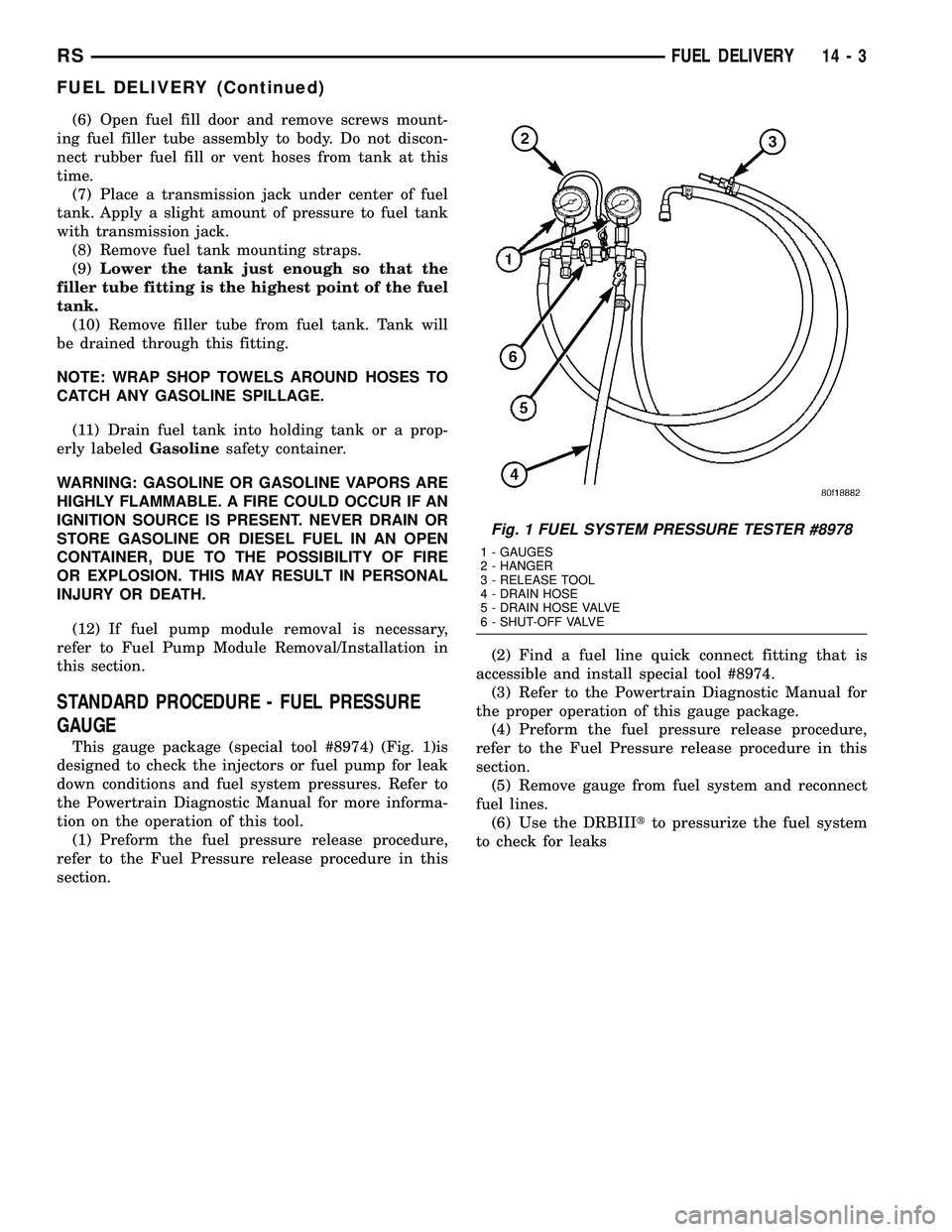
This gauge package (special tool #8974) (Fig. 1)is
designed to check the injectors or fuel pump for leak
down conditions and fuel system pressures. Refer to
the Powertrain Diagnostic Manual for more informa-
tion on the operation of this tool.
(1) Preform the fuel pressure release procedure,
refer to the Fuel Pressure release procedure in this
section.(2) Find a fuel line quick connect fitting that is
accessible and install special tool #8974.
(3) Refer to the Powertrain Diagnostic Manual for
the proper operation of this gauge package.
(4) Preform the fuel pressure release procedure,
refer to the Fuel Pressure release procedure in this
section.
(5) Remove gauge from fuel system and reconnect
fuel lines.
(6) Use the DRBIIItto pressurize the fuel system
to check for leaks
Fig. 1 FUEL SYSTEM PRESSURE TESTER #8978
1 - GAUGES
2 - HANGER
3 - RELEASE TOOL
4 - DRAIN HOSE
5 - DRAIN HOSE VALVE
6 - SHUT-OFF VALVE
RSFUEL DELIVERY14-3
FUEL DELIVERY (Continued)
Page 1381 of 2339

INSTALLATION - FOLD-IN-FLOOR
(1) Use a transmission jack to support fuel tank.
(2) Raise tank and install fuel filler vent tube thru
frame (Fig. 29).
(3) Raise tank.
(4) Connect the fuel fill hose at the fuel tank filler
metal tube and tighten clamp.
CAUTION: Ensure straps are not twisted or bent
before or after tightening strap bolts.
(5) Install bolts for fuel tank straps (Fig. 23).
(6) Tighten strap bolts to 54 N´m (40 ft. lbs.)
torque. Remove transmission jack.
(7) Connect the fuel filler vent tube.
(8) Connect fuel line and vapor line at the front of
the fuel tank (Fig. 25), (Fig. 26).
(9) Connect the electrical connector.
(10) Slide fuel pump module electrical connector
lock to lock (Fig. 27), (Fig. 28).
(11) Lower vehicle.
(12) Fill fuel tank, replace cap, and connect bat-
tery negative cable.
(13) Use the DRBIIItscan tool to pressurize the
fuel system. Check for leaks.
FUEL TANK FILLER TUBE
REMOVAL
(1) Disconnect the negative battery cable.
(2) Remove the 3 screws at the filler door.
(3) Raise and support vehicle
(4) Remove the left rear tire.
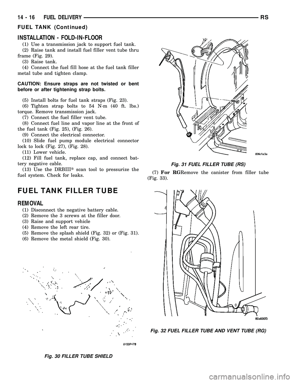
(5) Remove the splash shield (Fig. 32) or (Fig. 31).
(6) Remove the metal shield (Fig. 30).(7)For RGRemove the canister from filler tube
(Fig. 33).
Fig. 30 FILLER TUBE SHIELD
Fig. 31 FUEL FILLER TUBE (RS)
Fig. 32 FUEL FILLER TUBE AND VENT TUBE (RG)
14 - 16 FUEL DELIVERYRS
FUEL TANK (Continued)