2005 CHRYSLER VOYAGER wiring
[x] Cancel search: wiringPage 1374 of 2339
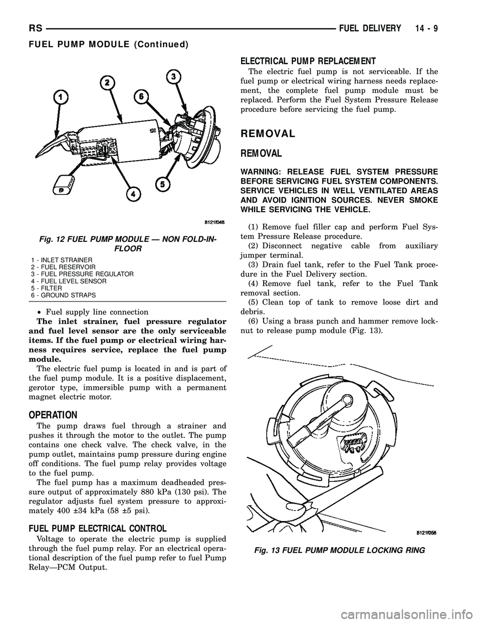
²Fuel supply line connection
The inlet strainer, fuel pressure regulator
and fuel level sensor are the only serviceable
items. If the fuel pump or electrical wiring har-
ness requires service, replace the fuel pump
module.
The electric fuel pump is located in and is part of
the fuel pump module. It is a positive displacement,
gerotor type, immersible pump with a permanent
magnet electric motor.
OPERATION
The pump draws fuel through a strainer and
pushes it through the motor to the outlet. The pump
contains one check valve. The check valve, in the
pump outlet, maintains pump pressure during engine
off conditions. The fuel pump relay provides voltage
to the fuel pump.
The fuel pump has a maximum deadheaded pres-
sure output of approximately 880 kPa (130 psi). The
regulator adjusts fuel system pressure to approxi-
mately 400 34 kPa (58 5 psi).
FUEL PUMP ELECTRICAL CONTROL
Voltage to operate the electric pump is supplied
through the fuel pump relay. For an electrical opera-
tional description of the fuel pump refer to fuel Pump
RelayÐPCM Output.
ELECTRICAL PUMP REPLACEMENT
The electric fuel pump is not serviceable. If the
fuel pump or electrical wiring harness needs replace-
ment, the complete fuel pump module must be
replaced. Perform the Fuel System Pressure Release
procedure before servicing the fuel pump.
REMOVAL
REMOVAL
WARNING: RELEASE FUEL SYSTEM PRESSURE
BEFORE SERVICING FUEL SYSTEM COMPONENTS.
SERVICE VEHICLES IN WELL VENTILATED AREAS
AND AVOID IGNITION SOURCES. NEVER SMOKE
WHILE SERVICING THE VEHICLE.
(1) Remove fuel filler cap and perform Fuel Sys-
tem Pressure Release procedure.
(2) Disconnect negative cable from auxiliary
jumper terminal.
(3) Drain fuel tank, refer to the Fuel Tank proce-
dure in the Fuel Delivery section.
(4) Remove fuel tank, refer to the Fuel Tank
removal section.
(5) Clean top of tank to remove loose dirt and
debris.
(6) Using a brass punch and hammer remove lock-
nut to release pump module (Fig. 13).
Fig. 12 FUEL PUMP MODULE Ð NON FOLD-IN-
FLOOR
1 - INLET STRAINER
2 - FUEL RESERVOIR
3 - FUEL PRESSURE REGULATOR
4 - FUEL LEVEL SENSOR
5 - FILTER
6 - GROUND STRAPS
Fig. 13 FUEL PUMP MODULE LOCKING RING
RSFUEL DELIVERY14-9
FUEL PUMP MODULE (Continued)
Page 1376 of 2339
FUEL RAIL
REMOVAL
REMOVAL - 2.4L
(1) Perform fuel system pressure release procedure
before servicing or starting repairs.Refer to
Fuel System Pressure Release Procedure in this sec-
tion.
(2) Disconnect negative cable from battery.
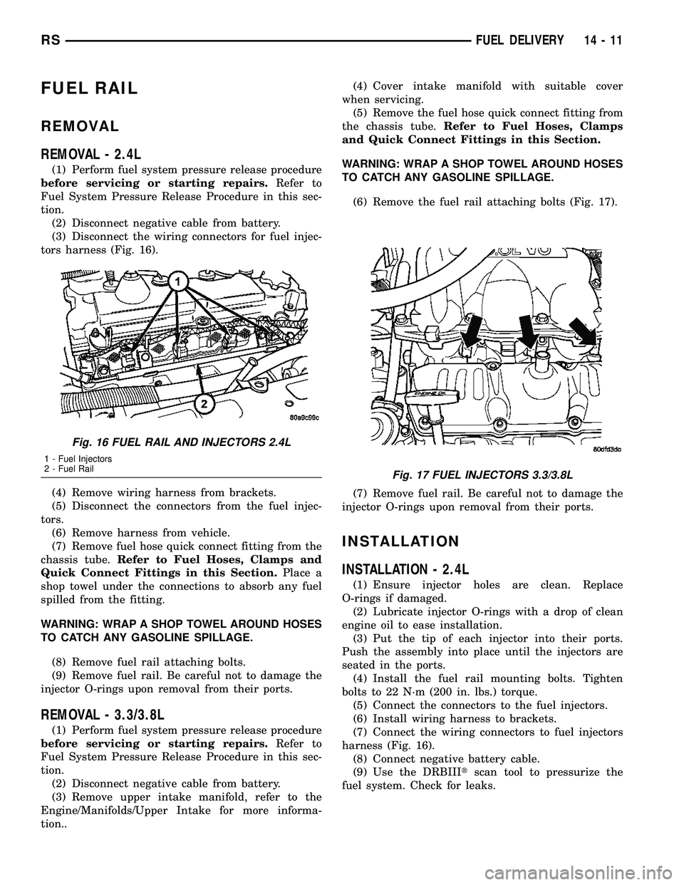
(3) Disconnect the wiring connectors for fuel injec-
tors harness (Fig. 16).
(4) Remove wiring harness from brackets.
(5) Disconnect the connectors from the fuel injec-
tors.
(6) Remove harness from vehicle.
(7) Remove fuel hose quick connect fitting from the
chassis tube.Refer to Fuel Hoses, Clamps and
Quick Connect Fittings in this Section.Place a
shop towel under the connections to absorb any fuel
spilled from the fitting.
WARNING: WRAP A SHOP TOWEL AROUND HOSES
TO CATCH ANY GASOLINE SPILLAGE.
(8) Remove fuel rail attaching bolts.
(9) Remove fuel rail. Be careful not to damage the
injector O-rings upon removal from their ports.
REMOVAL - 3.3/3.8L
(1) Perform fuel system pressure release procedure
before servicing or starting repairs.Refer to
Fuel System Pressure Release Procedure in this sec-
tion.
(2) Disconnect negative cable from battery.
(3) Remove upper intake manifold, refer to the
Engine/Manifolds/Upper Intake for more informa-
tion..(4) Cover intake manifold with suitable cover
when servicing.
(5) Remove the fuel hose quick connect fitting from
the chassis tube.Refer to Fuel Hoses, Clamps
and Quick Connect Fittings in this Section.
WARNING: WRAP A SHOP TOWEL AROUND HOSES
TO CATCH ANY GASOLINE SPILLAGE.
(6) Remove the fuel rail attaching bolts (Fig. 17).
(7) Remove fuel rail. Be careful not to damage the
injector O-rings upon removal from their ports.
INSTALLATION
INSTALLATION - 2.4L
(1) Ensure injector holes are clean. Replace
O-rings if damaged.
(2) Lubricate injector O-rings with a drop of clean
engine oil to ease installation.
(3) Put the tip of each injector into their ports.
Push the assembly into place until the injectors are
seated in the ports.
(4) Install the fuel rail mounting bolts. Tighten
bolts to 22 N´m (200 in. lbs.) torque.
(5) Connect the connectors to the fuel injectors.
(6) Install wiring harness to brackets.
(7) Connect the wiring connectors to fuel injectors
harness (Fig. 16).
(8) Connect negative battery cable.
(9) Use the DRBIIItscan tool to pressurize the
fuel system. Check for leaks.
Fig. 16 FUEL RAIL AND INJECTORS 2.4L
1 - Fuel Injectors
2 - Fuel Rail
Fig. 17 FUEL INJECTORS 3.3/3.8L
RSFUEL DELIVERY14-11
Page 1390 of 2339
opposite preset limit or switch point. The process
then repeats itself in the opposite direction.
Short term fuel correction will keep increasing or
decreasing injector pulse-width based upon the
upstream O2 Sensor input. The maximum range of
authority for short term memory is 25% (+/-) of base
pulse-width. Short term is violated and is lost when
ignition is turned OFF.
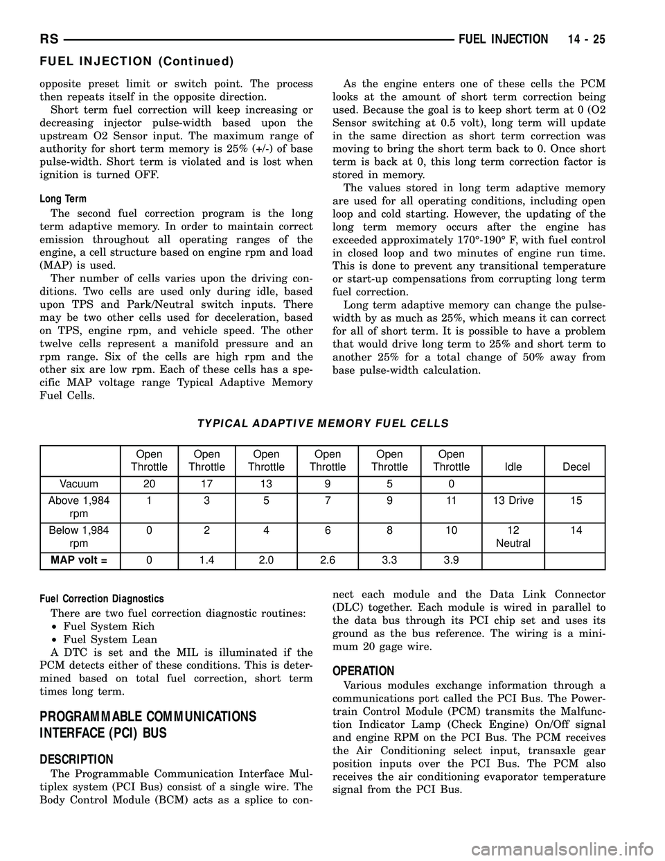
Long Term
The second fuel correction program is the long
term adaptive memory. In order to maintain correct
emission throughout all operating ranges of the
engine, a cell structure based on engine rpm and load
(MAP) is used.
Ther number of cells varies upon the driving con-
ditions. Two cells are used only during idle, based
upon TPS and Park/Neutral switch inputs. There
may be two other cells used for deceleration, based
on TPS, engine rpm, and vehicle speed. The other
twelve cells represent a manifold pressure and an
rpm range. Six of the cells are high rpm and the
other six are low rpm. Each of these cells has a spe-
cific MAP voltage range Typical Adaptive Memory
Fuel Cells.As the engine enters one of these cells the PCM
looks at the amount of short term correction being
used. Because the goal is to keep short term at 0 (O2
Sensor switching at 0.5 volt), long term will update
in the same direction as short term correction was
moving to bring the short term back to 0. Once short
term is back at 0, this long term correction factor is
stored in memory.
The values stored in long term adaptive memory
are used for all operating conditions, including open
loop and cold starting. However, the updating of the
long term memory occurs after the engine has
exceeded approximately 170É-190É F, with fuel control
in closed loop and two minutes of engine run time.
This is done to prevent any transitional temperature
or start-up compensations from corrupting long term
fuel correction.
Long term adaptive memory can change the pulse-
width by as much as 25%, which means it can correct
for all of short term. It is possible to have a problem
that would drive long term to 25% and short term to
another 25% for a total change of 50% away from
base pulse-width calculation.
TYPICAL ADAPTIVE MEMORY FUEL CELLS
Open
ThrottleOpen
ThrottleOpen
ThrottleOpen
ThrottleOpen
ThrottleOpen
Throttle Idle Decel
Vacuum 20 17 13 9 5 0
Above 1,984
rpm1 3 5 7 9 11 13 Drive 15
Below 1,984
rpm02 4 6 8 1012
Neutral14
MAP volt =0 1.4 2.0 2.6 3.3 3.9
Fuel Correction Diagnostics
There are two fuel correction diagnostic routines:
²Fuel System Rich
²Fuel System Lean
A DTC is set and the MIL is illuminated if the
PCM detects either of these conditions. This is deter-
mined based on total fuel correction, short term
times long term.
PROGRAMMABLE COMMUNICATIONS
INTERFACE (PCI) BUS
DESCRIPTION
The Programmable Communication Interface Mul-
tiplex system (PCI Bus) consist of a single wire. The
Body Control Module (BCM) acts as a splice to con-nect each module and the Data Link Connector
(DLC) together. Each module is wired in parallel to
the data bus through its PCI chip set and uses its
ground as the bus reference. The wiring is a mini-
mum 20 gage wire.
OPERATION
Various modules exchange information through a
communications port called the PCI Bus. The Power-
train Control Module (PCM) transmits the Malfunc-
tion Indicator Lamp (Check Engine) On/Off signal
and engine RPM on the PCI Bus. The PCM receives
the Air Conditioning select input, transaxle gear
position inputs over the PCI Bus. The PCM also
receives the air conditioning evaporator temperature
signal from the PCI Bus.
RSFUEL INJECTION14-25
FUEL INJECTION (Continued)
Page 1396 of 2339
OPERATION
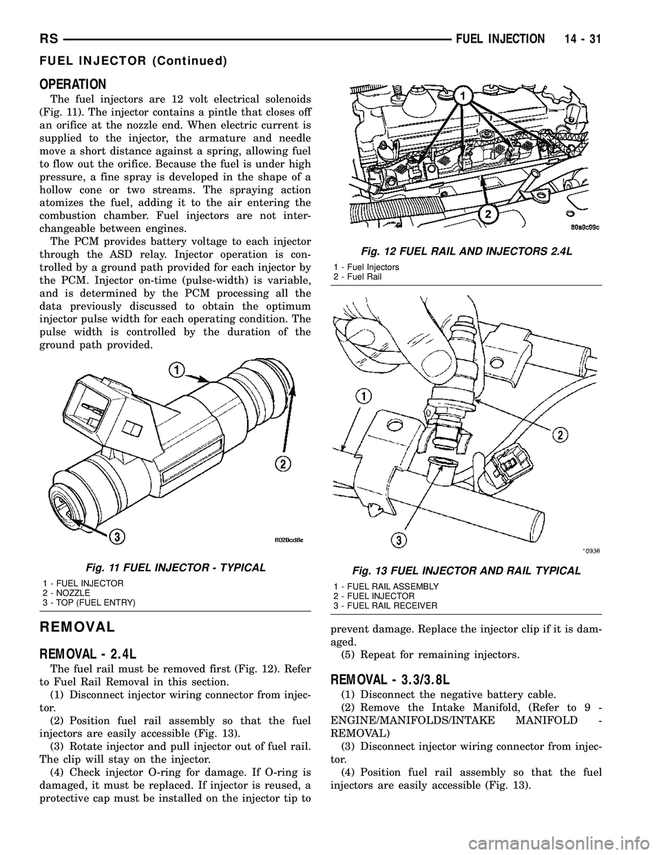
The fuel injectors are 12 volt electrical solenoids
(Fig. 11). The injector contains a pintle that closes off
an orifice at the nozzle end. When electric current is
supplied to the injector, the armature and needle
move a short distance against a spring, allowing fuel
to flow out the orifice. Because the fuel is under high
pressure, a fine spray is developed in the shape of a
hollow cone or two streams. The spraying action
atomizes the fuel, adding it to the air entering the
combustion chamber. Fuel injectors are not inter-
changeable between engines.
The PCM provides battery voltage to each injector
through the ASD relay. Injector operation is con-
trolled by a ground path provided for each injector by
the PCM. Injector on-time (pulse-width) is variable,
and is determined by the PCM processing all the
data previously discussed to obtain the optimum
injector pulse width for each operating condition. The
pulse width is controlled by the duration of the
ground path provided.
REMOVAL
REMOVAL - 2.4L
The fuel rail must be removed first (Fig. 12). Refer
to Fuel Rail Removal in this section.
(1) Disconnect injector wiring connector from injec-
tor.
(2) Position fuel rail assembly so that the fuel
injectors are easily accessible (Fig. 13).
(3) Rotate injector and pull injector out of fuel rail.
The clip will stay on the injector.
(4) Check injector O-ring for damage. If O-ring is
damaged, it must be replaced. If injector is reused, a
protective cap must be installed on the injector tip toprevent damage. Replace the injector clip if it is dam-
aged.
(5) Repeat for remaining injectors.
REMOVAL - 3.3/3.8L
(1) Disconnect the negative battery cable.
(2) Remove the Intake Manifold, (Refer to 9 -
ENGINE/MANIFOLDS/INTAKE MANIFOLD -
REMOVAL)
(3) Disconnect injector wiring connector from injec-
tor.
(4) Position fuel rail assembly so that the fuel
injectors are easily accessible (Fig. 13).
Fig. 11 FUEL INJECTOR - TYPICAL
1 - FUEL INJECTOR
2 - NOZZLE
3 - TOP (FUEL ENTRY)
Fig. 12 FUEL RAIL AND INJECTORS 2.4L
1 - Fuel Injectors
2 - Fuel Rail
Fig. 13 FUEL INJECTOR AND RAIL TYPICAL
1 - FUEL RAIL ASSEMBLY
2 - FUEL INJECTOR
3 - FUEL RAIL RECEIVER
RSFUEL INJECTION14-31
FUEL INJECTOR (Continued)
Page 1397 of 2339
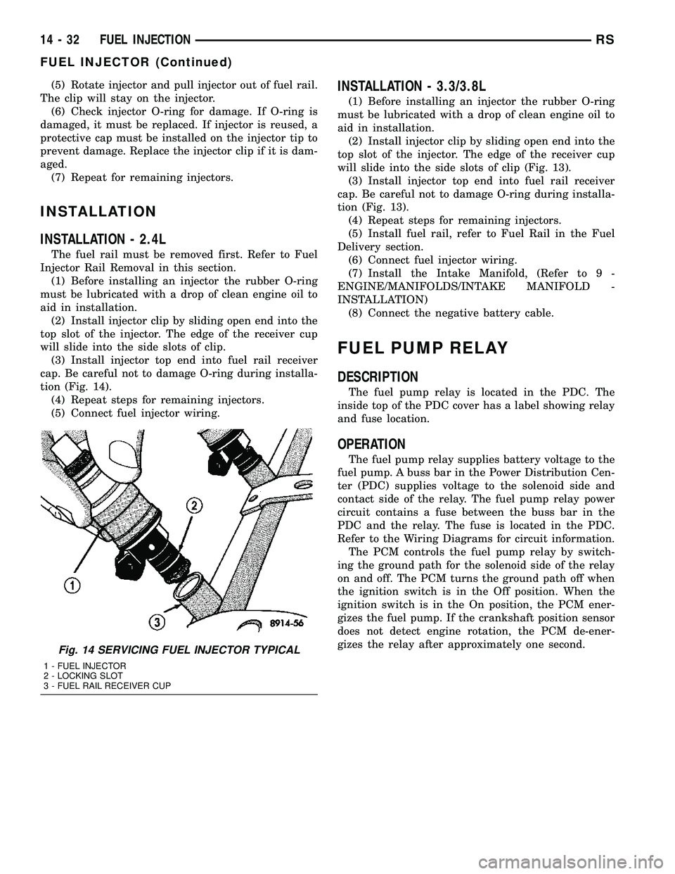
(5) Rotate injector and pull injector out of fuel rail.
The clip will stay on the injector.
(6) Check injector O-ring for damage. If O-ring is
damaged, it must be replaced. If injector is reused, a
protective cap must be installed on the injector tip to
prevent damage. Replace the injector clip if it is dam-
aged.
(7) Repeat for remaining injectors.
INSTALLATION
INSTALLATION - 2.4L
The fuel rail must be removed first. Refer to Fuel
Injector Rail Removal in this section.
(1) Before installing an injector the rubber O-ring
must be lubricated with a drop of clean engine oil to
aid in installation.
(2) Install injector clip by sliding open end into the
top slot of the injector. The edge of the receiver cup
will slide into the side slots of clip.
(3) Install injector top end into fuel rail receiver
cap. Be careful not to damage O-ring during installa-
tion (Fig. 14).
(4) Repeat steps for remaining injectors.
(5) Connect fuel injector wiring.
INSTALLATION - 3.3/3.8L
(1) Before installing an injector the rubber O-ring
must be lubricated with a drop of clean engine oil to
aid in installation.
(2) Install injector clip by sliding open end into the
top slot of the injector. The edge of the receiver cup
will slide into the side slots of clip (Fig. 13).
(3) Install injector top end into fuel rail receiver
cap. Be careful not to damage O-ring during installa-
tion (Fig. 13).
(4) Repeat steps for remaining injectors.
(5) Install fuel rail, refer to Fuel Rail in the Fuel
Delivery section.
(6) Connect fuel injector wiring.
(7) Install the Intake Manifold, (Refer to 9 -
ENGINE/MANIFOLDS/INTAKE MANIFOLD -
INSTALLATION)
(8) Connect the negative battery cable.
FUEL PUMP RELAY
DESCRIPTION
The fuel pump relay is located in the PDC. The
inside top of the PDC cover has a label showing relay
and fuse location.
OPERATION
The fuel pump relay supplies battery voltage to the
fuel pump. A buss bar in the Power Distribution Cen-
ter (PDC) supplies voltage to the solenoid side and
contact side of the relay. The fuel pump relay power
circuit contains a fuse between the buss bar in the
PDC and the relay. The fuse is located in the PDC.
Refer to the Wiring Diagrams for circuit information.
The PCM controls the fuel pump relay by switch-
ing the ground path for the solenoid side of the relay
on and off. The PCM turns the ground path off when
the ignition switch is in the Off position. When the
ignition switch is in the On position, the PCM ener-
gizes the fuel pump. If the crankshaft position sensor
does not detect engine rotation, the PCM de-ener-
gizes the relay after approximately one second.
Fig. 14 SERVICING FUEL INJECTOR TYPICAL
1 - FUEL INJECTOR
2 - LOCKING SLOT
3 - FUEL RAIL RECEIVER CUP
14 - 32 FUEL INJECTIONRS
FUEL INJECTOR (Continued)
Page 1418 of 2339
WARNING: THE AIR BAG SYSTEM IS A SENSITIVE,
COMPLEX ELECTRO-MECHANICAL UNIT. BEFORE
ATTEMPTING TO DIAGNOSE, REMOVE OR INSTALL
THE AIR BAG SYSTEM COMPONENTS YOU MUST
FIRST DISCONNECT AND ISOLATE THE BATTERY
NEGATIVE (GROUND) CABLE. THEN WAIT TWO
MINUTES FOR THE SYSTEM CAPACITOR TO DIS-
CHARGE. FAILURE TO DO SO COULD RESULT IN
ACCIDENTAL DEPLOYMENT OF THE AIR BAG AND
POSSIBLE PERSONAL INJURY. THE FASTENERS,
SCREWS, AND BOLTS, ORIGINALLY USED FOR
THE AIR BAG COMPONENTS, HAVE SPECIAL
COATINGS AND ARE SPECIFICALLY DESIGNED
FOR THE AIR BAG SYSTEM. THEY MUST NEVER
BE REPLACED WITH ANY SUBSTITUTES. ANYTIME
A NEW FASTENER IS NEEDED, REPLACE WITH
THE CORRECT FASTENERS PROVIDED IN THE
SERVICE PACKAGE OR FASTENERS LISTED IN
THE PARTS BOOKS.
WARNING: SAFETY GOGGLES SHOULD BE WORN
AT ALL TIMES WHEN WORKING ON STEERING
COLUMNS.
CAUTION: Disconnect negative (ground) cable from
the battery before servicing any column compo-
nent.
CAUTION: Do not attempt to remove the pivot pins
to disassemble the tilting mechanism. Damage will
occur.
DIAGNOSIS AND TESTING - STEERING
COLUMN
For diagnosis of conditions relating to the steering
column, (Refer to 19 - STEERING - DIAGNOSIS
AND TESTING).
REMOVAL
NOTE: Before proceeding, (Refer to 19 - STEERING/
COLUMN - WARNING)(Refer to 8 - ELECTRICAL/RE-
STRAINTS/DRIVER AIRBAG - REMOVAL).
(1) Make sure the front wheels of the vehicle are
in the STRAIGHT AHEAD position before beginning
the column removal procedure.
(2) Disconnect and isolate the negative (ground)
cable from the battery. Wait at least two minutes for
the airbag system reserve capacitor to discharge
before beginning any steering column, instrument
panel, or airbag system/component service.WARNING: WHEN AN UNDEPLOYED AIRBAG IS TO
BE REMOVED FROM THE VEHICLE, FIRST DISCON-
NECT AND ISOLATE THE BATTERY NEGATIVE
(GROUND) CABLE. ALLOW THE AIRBAG SYSTEM
RESERVE CAPACITOR TO DISCHARGE FOR TWO
MINUTES BEFORE BEGINNING ANY AIRBAG SYS-
TEM OR COMPONENT SERVICE. PERSONAL
INJURY MAY RESULT IF THIS PROCEDURE IS NOT
FOLLOWED.
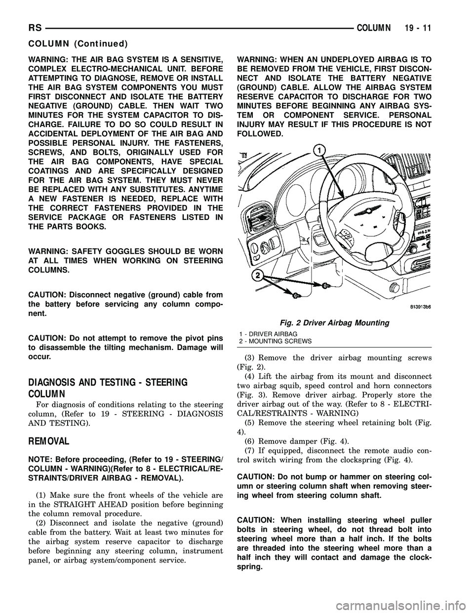
(3) Remove the driver airbag mounting screws
(Fig. 2).
(4) Lift the airbag from its mount and disconnect
two airbag squib, speed control and horn connectors
(Fig. 3). Remove driver airbag. Properly store the
driver airbag out of the way. (Refer to 8 - ELECTRI-
CAL/RESTRAINTS - WARNING)
(5) Remove the steering wheel retaining bolt (Fig.
4).
(6) Remove damper (Fig. 4).
(7) If equipped, disconnect the remote audio con-
trol switch wiring from the clockspring (Fig. 4).
CAUTION: Do not bump or hammer on steering col-
umn or steering column shaft when removing steer-
ing wheel from steering column shaft.
CAUTION: When installing steering wheel puller
bolts in steering wheel, do not thread bolt into
steering wheel more than a half inch. If the bolts
are threaded into the steering wheel more than a
half inch they will contact and damage the clock-
spring.
Fig. 2 Driver Airbag Mounting
1 - DRIVER AIRBAG
2 - MOUNTING SCREWS
RSCOLUMN19-11
COLUMN (Continued)
Page 1419 of 2339
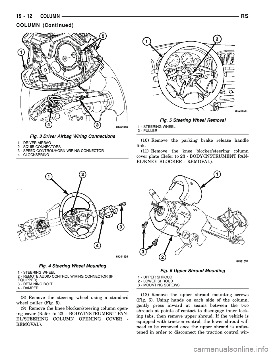
(8) Remove the steering wheel using a standard
wheel puller (Fig. 5).
(9) Remove the knee blocker/steering column open-
ing cover (Refer to 23 - BODY/INSTRUMENT PAN-
EL/STEERING COLUMN OPENING COVER -
REMOVAL).(10) Remove the parking brake release handle
link.
(11) Remove the knee blocker/steering column
cover plate (Refer to 23 - BODY/INSTRUMENT PAN-
EL/KNEE BLOCKER - REMOVAL).
(12) Remove the upper shroud mounting screws
(Fig. 6). Using hands on each side of the column,
gently press inward at seams between the two
shrouds at points of contact to disengage inner lock-
ing tabs, then remove upper shroud. If the vehicle is
equipped with traction control, the lower shroud will
need to be removed once the upper shroud is unfas-
tened in order to disconnect the traction control wir-
Fig. 3 Driver Airbag Wiring Connections
1 - DRIVER AIRBAG
2 - SQUIB CONNECTORS
3 - SPEED CONTROL/HORN WIRING CONNECTOR
4 - CLOCKSPRING
Fig. 4 Steering Wheel Mounting
1 - STEERING WHEEL
2 - REMOTE AUDIO CONTROL WIRING CONNECTOR (IF
EQUIPPED)
3 - RETAINING BOLT
4 - DAMPER
Fig. 5 Steering Wheel Removal
1 - STEERING WHEEL
2 - PULLER
Fig. 6 Upper Shroud Mounting
1 - UPPER SHROUD
2 - LOWER SHROUD
3 - MOUNTING SCREWS
19 - 12 COLUMNRS
COLUMN (Continued)
Page 1420 of 2339
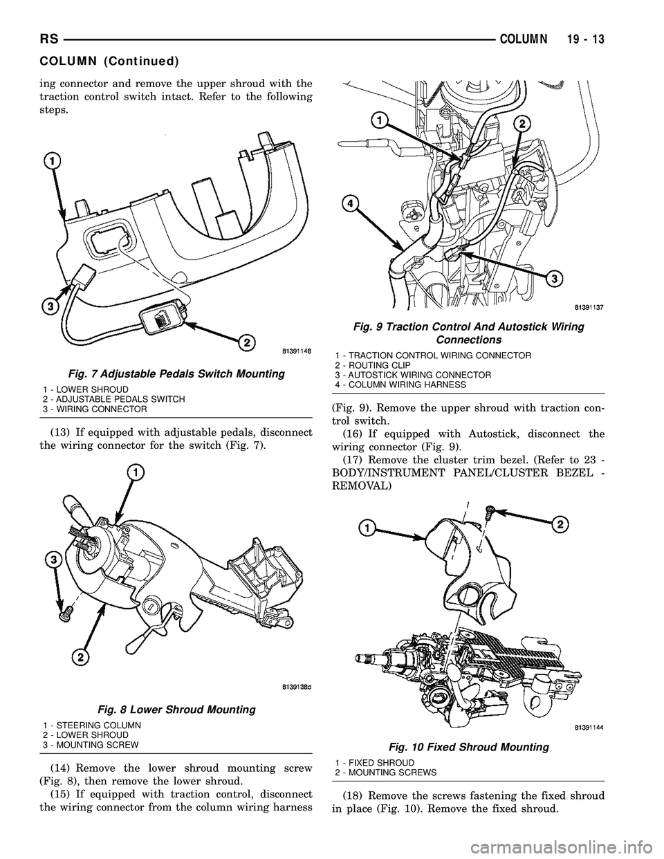
ing connector and remove the upper shroud with the
traction control switch intact. Refer to the following
steps.
(13) If equipped with adjustable pedals, disconnect
the wiring connector for the switch (Fig. 7).
(14) Remove the lower shroud mounting screw
(Fig. 8), then remove the lower shroud.
(15) If equipped with traction control, disconnect
the wiring connector from the column wiring harness(Fig. 9). Remove the upper shroud with traction con-
trol switch.
(16) If equipped with Autostick, disconnect the
wiring connector (Fig. 9).
(17) Remove the cluster trim bezel. (Refer to 23 -
BODY/INSTRUMENT PANEL/CLUSTER BEZEL -
REMOVAL)
(18) Remove the screws fastening the fixed shroud
in place (Fig. 10). Remove the fixed shroud.
Fig. 7 Adjustable Pedals Switch Mounting
1 - LOWER SHROUD
2 - ADJUSTABLE PEDALS SWITCH
3 - WIRING CONNECTOR
Fig. 8 Lower Shroud Mounting
1 - STEERING COLUMN
2 - LOWER SHROUD
3 - MOUNTING SCREW
Fig. 9 Traction Control And Autostick Wiring
Connections
1 - TRACTION CONTROL WIRING CONNECTOR
2 - ROUTING CLIP
3 - AUTOSTICK WIRING CONNECTOR
4 - COLUMN WIRING HARNESS
Fig. 10 Fixed Shroud Mounting
1 - FIXED SHROUD
2 - MOUNTING SCREWS
RSCOLUMN19-13
COLUMN (Continued)