2005 CHRYSLER VOYAGER ABS
[x] Cancel search: ABSPage 1836 of 2339
(2) Insert ends of crossmember between layered
metal sections of radiator closure panel at each side
of radiator.
(3) Align with paint breaks around bolt heads.
(4) Install bolts attaching ends of crossmember to
radiator closure panel (Fig. 16). Tighten bolts to 19
N´m (14 ft. lbs.) torque.
(5) Install bolts attaching radiator isolators to
crossmember.
(6) Install screw attaching coolant recovery bottle
to crossmember.
(7) Install bolt attaching air cleaner housing to
crossmember.
(8) Install engine air inlet resonator.
(9) Install hood prop rod.
(10) Align hood latch by placing latch over net
pierce tabs. If alignment is required, flatten tabs.
(11) Install bolts attaching hood latch to cross-
member and clip cable. Tighten bolts to 13.5 N´m (10
ft. lbs.) torque.
(12) Install radiator sight shield.
(13) Verify hood latch operation and hood align-
ment.
FRONT WHEELHOUSE
SPLASH SHIELD
REMOVAL
(1) Hoist and support vehicle on safety stands.
(Refer to LUBRICATION & MAINTENANCE/HOIST-
ING - STANDARD PROCEDURE).
(2) Remove front wheel.
(3) Remove push pin fasteners attaching splash
shield to frame rail forward of suspension.
(4) Remove push pin fasteners attaching splash
shield to frame rail rearward of suspension.
(5) Remove screws attaching wheelhouse splash
shield to front fender and front bumper fascia.
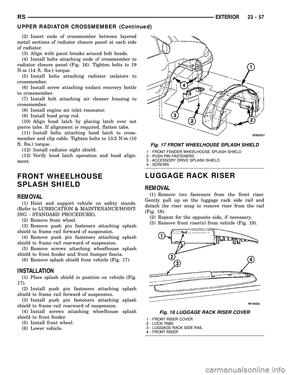
(6) Remove splash shield from vehicle (Fig. 17).
INSTALLATION
(1) Place splash shield in position on vehicle (Fig.
17).
(2) Install push pin fasteners attaching splash
shield to frame rail forward of suspension.
(3) Install push pin fasteners attaching splash
shield to frame rail rearward of suspension.
(4) Install screws attaching wheelhouse splash
shield to front fender.
(5) Install front wheel.
(6) Lower vehicle.
LUGGAGE RACK RISER
REMOVAL
(1) Remove two fasteners from the front riser.
Gently pull up on the luggage rack side rail and
detach the riser snap to remove riser from the rail
(Fig. 18).
(2) Repeat for the opposite side, if necessary.
(3) Remove front riser(s) from vehicle (Fig. 19).
Fig. 17 FRONT WHEELHOUSE SPLASH SHIELD
1 - FRONT FENDER WHEELHOUSE SPLASH SHIELD
2 - PUSH PIN FASTENERS
3 - ACCESSORY DRIVE SPLASH SHIELD
4 - SCREWS
Fig. 18 LUGGAGE RACK RISER COVER
1 - FRONT RISER COVER
2 - LOCK TABS
3 - LUGGAGE RACK SIDE RAIL
4 - FRONT RISER
RSEXTERIOR23-57
UPPER RADIATOR CROSSMEMBER (Continued)
Page 1842 of 2339
INSTALLATION
(1) Place hood in position on vehicle. With assis-
tance from a helper at the opposite side of the vehicle
to support the hood, install bottom bolts attaching
hood to hinge finger tight.
(2) Install top bolts attaching hood to hinge finger
tight.
(3) Position bolts at marks and tighten. Tighten
bolts to 13.5 N´m (120 in. lbs.) torque. The hood
should be aligned to 4 mm (0.160 in.) gap to the front
fenders and flush across the top surfaces along fend-
ers.
(4) Verify hood operation and alignment.
LATCH
REMOVAL
(1) Release hood latch and open hood.
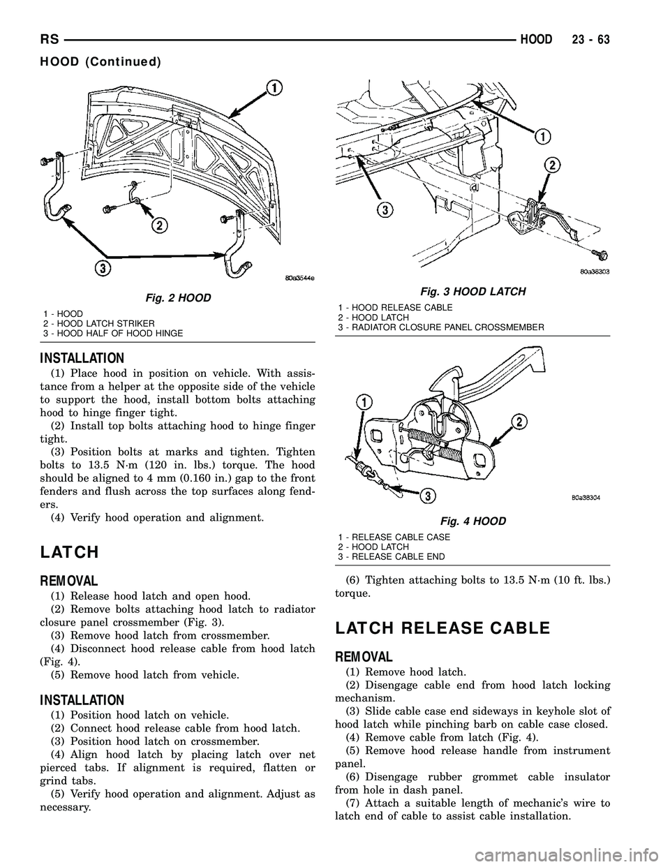
(2) Remove bolts attaching hood latch to radiator
closure panel crossmember (Fig. 3).
(3) Remove hood latch from crossmember.
(4) Disconnect hood release cable from hood latch
(Fig. 4).
(5) Remove hood latch from vehicle.
INSTALLATION
(1) Position hood latch on vehicle.
(2) Connect hood release cable from hood latch.
(3) Position hood latch on crossmember.
(4) Align hood latch by placing latch over net
pierced tabs. If alignment is required, flatten or
grind tabs.
(5) Verify hood operation and alignment. Adjust as
necessary.(6) Tighten attaching bolts to 13.5 N´m (10 ft. lbs.)
torque.
LATCH RELEASE CABLE
REMOVAL
(1) Remove hood latch.
(2) Disengage cable end from hood latch locking
mechanism.
(3) Slide cable case end sideways in keyhole slot of
hood latch while pinching barb on cable case closed.
(4) Remove cable from latch (Fig. 4).
(5) Remove hood release handle from instrument
panel.
(6) Disengage rubber grommet cable insulator
from hole in dash panel.
(7) Attach a suitable length of mechanic's wire to
latch end of cable to assist cable installation.
Fig. 2 HOOD
1 - HOOD
2 - HOOD LATCH STRIKER
3 - HOOD HALF OF HOOD HINGE
Fig. 3 HOOD LATCH
1 - HOOD RELEASE CABLE
2 - HOOD LATCH
3 - RADIATOR CLOSURE PANEL CROSSMEMBER
Fig. 4 HOOD
1 - RELEASE CABLE CASE
2 - HOOD LATCH
3 - RELEASE CABLE END
RSHOOD23-63
HOOD (Continued)
Page 1868 of 2339
DOOR SILL TRIM PLATE
REMOVAL
(1) Using trim stick (C-4755), disengage hidden
clips holding door sill plate from door sill.
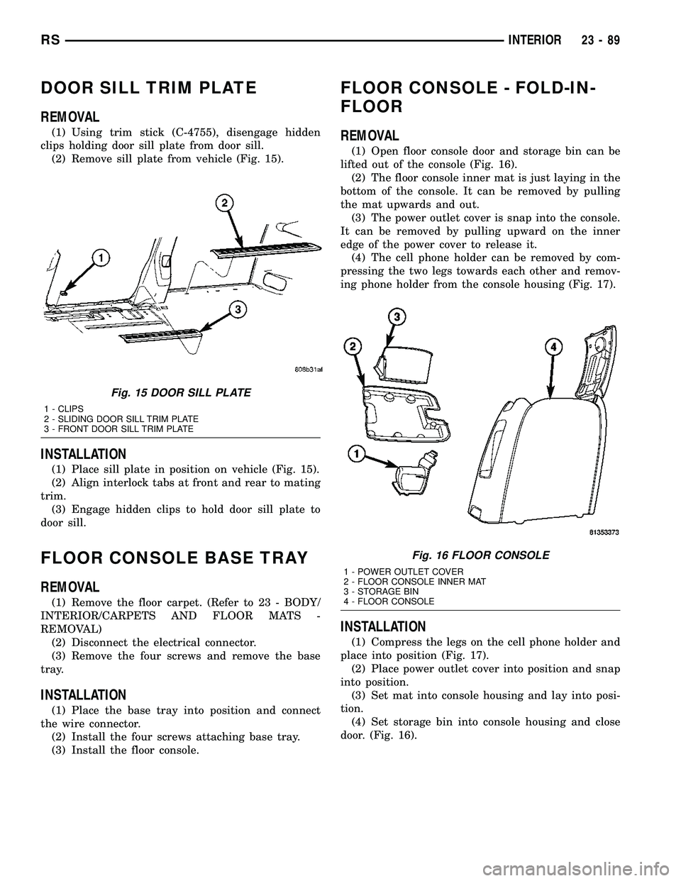
(2) Remove sill plate from vehicle (Fig. 15).
INSTALLATION
(1) Place sill plate in position on vehicle (Fig. 15).
(2) Align interlock tabs at front and rear to mating
trim.
(3) Engage hidden clips to hold door sill plate to
door sill.
FLOOR CONSOLE BASE TRAY
REMOVAL
(1) Remove the floor carpet. (Refer to 23 - BODY/
INTERIOR/CARPETS AND FLOOR MATS -
REMOVAL)
(2) Disconnect the electrical connector.
(3) Remove the four screws and remove the base
tray.
INSTALLATION
(1) Place the base tray into position and connect
the wire connector.
(2) Install the four screws attaching base tray.
(3) Install the floor console.
FLOOR CONSOLE - FOLD-IN-
FLOOR
REMOVAL
(1) Open floor console door and storage bin can be
lifted out of the console (Fig. 16).
(2) The floor console inner mat is just laying in the
bottom of the console. It can be removed by pulling
the mat upwards and out.
(3) The power outlet cover is snap into the console.
It can be removed by pulling upward on the inner
edge of the power cover to release it.
(4) The cell phone holder can be removed by com-
pressing the two legs towards each other and remov-
ing phone holder from the console housing (Fig. 17).
INSTALLATION
(1) Compress the legs on the cell phone holder and
place into position (Fig. 17).
(2) Place power outlet cover into position and snap
into position.
(3) Set mat into console housing and lay into posi-
tion.
(4) Set storage bin into console housing and close
door. (Fig. 16).
Fig. 15 DOOR SILL PLATE
1 - CLIPS
2 - SLIDING DOOR SILL TRIM PLATE
3 - FRONT DOOR SILL TRIM PLATE
Fig. 16 FLOOR CONSOLE
1 - POWER OUTLET COVER
2 - FLOOR CONSOLE INNER MAT
3 - STORAGE BIN
4 - FLOOR CONSOLE
RSINTERIOR23-89
Page 1874 of 2339
INSTALLATION
(1) Place sill plate in position on vehicle.
(2) Align engage hook tabs at end of liftgate sill
plate to D-pillar trim.
(3) Engage hidden clips to hold sill plate to liftgate
door opening sill.
QUARTER TRIM BOLSTER
REMOVAL
The speaker grille in the quarter trim panel is not
removable. The trim panel must be removed to ser-
vice the speaker.
(1) Disengage hidden clips attaching trim bolster
to quarter trim panel.
(2) Remove quarter trim panel from vehicle.
INSTALLATION
The speaker grille in the quarter trim bolster is
not removable. The trim bolster must removed to ser-
vice the speaker.
(1) Place quarter trim bolster in position on vehi-
cle.
(2) Engage hook retainer attaching front of trim
bolster to quarter trim panel, if applicable.
(3) Engage hidden clips attaching trim bolster to
quarter trim panel.
REAR FLOOR TUB CARPETS
INSERT - FOLD-IN-FLOOR
REMOVAL
(1) Open liftgate.
(2) Remove liftgate sill plate. (Refer to 23 - BODY/
INTERIOR/LIFTGATE SILL PLATE - REMOVAL).
(3) Fold third row seats in to floor well.
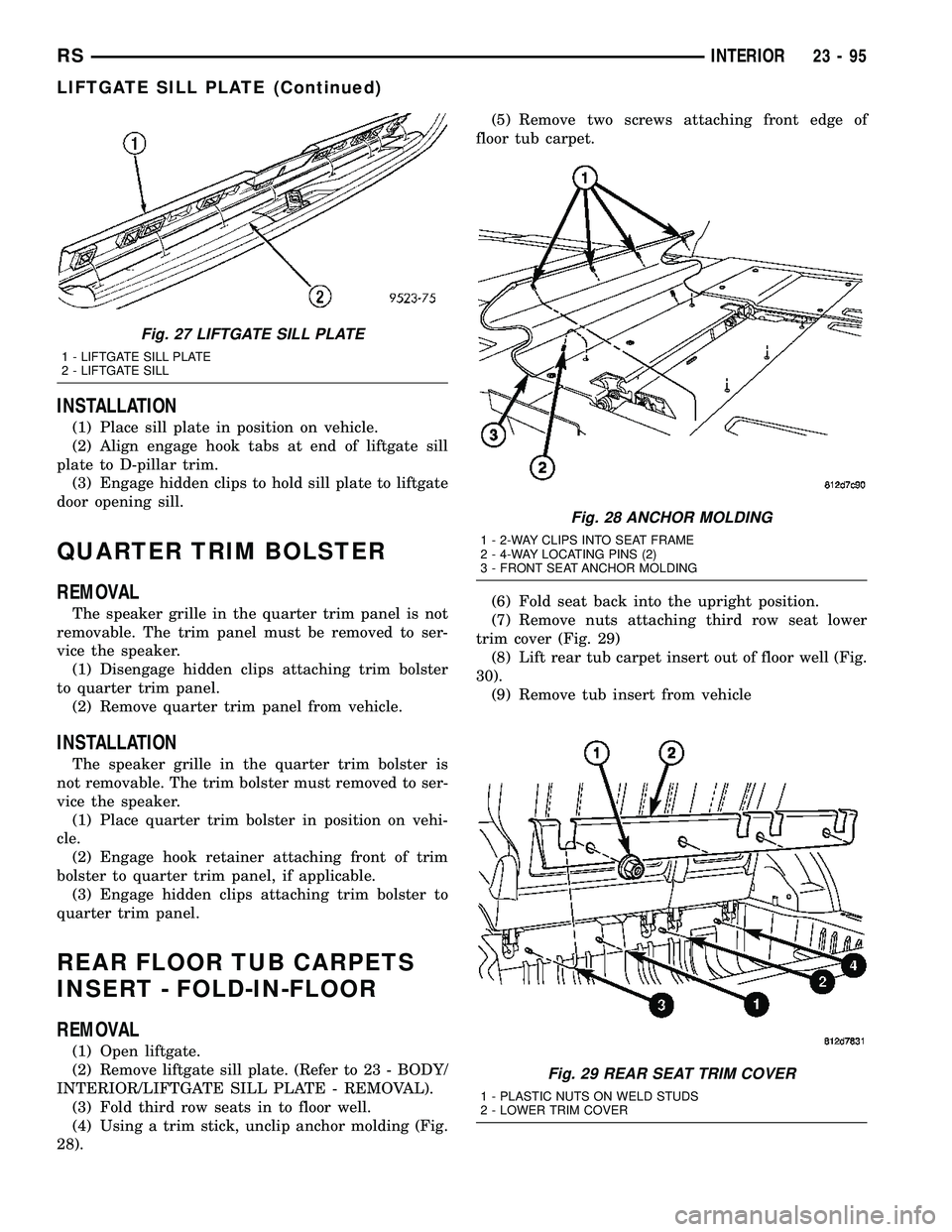
(4) Using a trim stick, unclip anchor molding (Fig.
28).(5) Remove two screws attaching front edge of
floor tub carpet.
(6) Fold seat back into the upright position.
(7) Remove nuts attaching third row seat lower
trim cover (Fig. 29)
(8) Lift rear tub carpet insert out of floor well (Fig.
30).
(9) Remove tub insert from vehicle
Fig. 27 LIFTGATE SILL PLATE
1 - LIFTGATE SILL PLATE
2 - LIFTGATE SILL
Fig. 28 ANCHOR MOLDING
1 - 2-WAY CLIPS INTO SEAT FRAME
2 - 4-WAY LOCATING PINS (2)
3 - FRONT SEAT ANCHOR MOLDING
Fig. 29 REAR SEAT TRIM COVER
1 - PLASTIC NUTS ON WELD STUDS
2 - LOWER TRIM COVER
RSINTERIOR23-95
LIFTGATE SILL PLATE (Continued)
Page 1875 of 2339
INSTALLATION
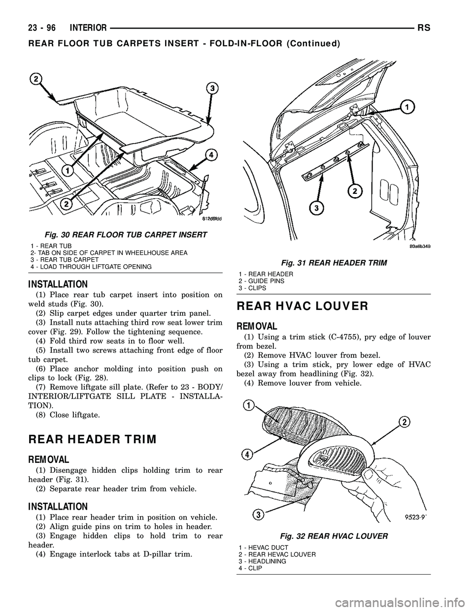
(1) Place rear tub carpet insert into position on
weld studs (Fig. 30).
(2) Slip carpet edges under quarter trim panel.
(3) Install nuts attaching third row seat lower trim
cover (Fig. 29). Follow the tightening sequence.
(4) Fold third row seats in to floor well.
(5) Install two screws attaching front edge of floor
tub carpet.
(6) Place anchor molding into position push on
clips to lock (Fig. 28).
(7) Remove liftgate sill plate. (Refer to 23 - BODY/
INTERIOR/LIFTGATE SILL PLATE - INSTALLA-
TION).
(8) Close liftgate.
REAR HEADER TRIM
REMOVAL
(1) Disengage hidden clips holding trim to rear
header (Fig. 31).
(2) Separate rear header trim from vehicle.
INSTALLATION
(1) Place rear header trim in position on vehicle.
(2) Align guide pins on trim to holes in header.
(3) Engage hidden clips to hold trim to rear
header.
(4) Engage interlock tabs at D-pillar trim.
REAR HVAC LOUVER
REMOVAL
(1) Using a trim stick (C-4755), pry edge of louver
from bezel.
(2) Remove HVAC louver from bezel.
(3) Using a trim stick, pry lower edge of HVAC
bezel away from headlining (Fig. 32).
(4) Remove louver from vehicle.
Fig. 30 REAR FLOOR TUB CARPET INSERT
1 - REAR TUB
2- TAB ON SIDE OF CARPET IN WHEELHOUSE AREA
3 - REAR TUB CARPET
4 - LOAD THROUGH LIFTGATE OPENING
Fig. 31 REAR HEADER TRIM
1 - REAR HEADER
2 - GUIDE PINS
3 - CLIPS
Fig. 32 REAR HVAC LOUVER
1 - HEVAC DUCT
2 - REAR HEVAC LOUVER
3 - HEADLINING
4 - CLIP
23 - 96 INTERIORRS
REAR FLOOR TUB CARPETS INSERT - FOLD-IN-FLOOR (Continued)
Page 1878 of 2339
INSTALLATION
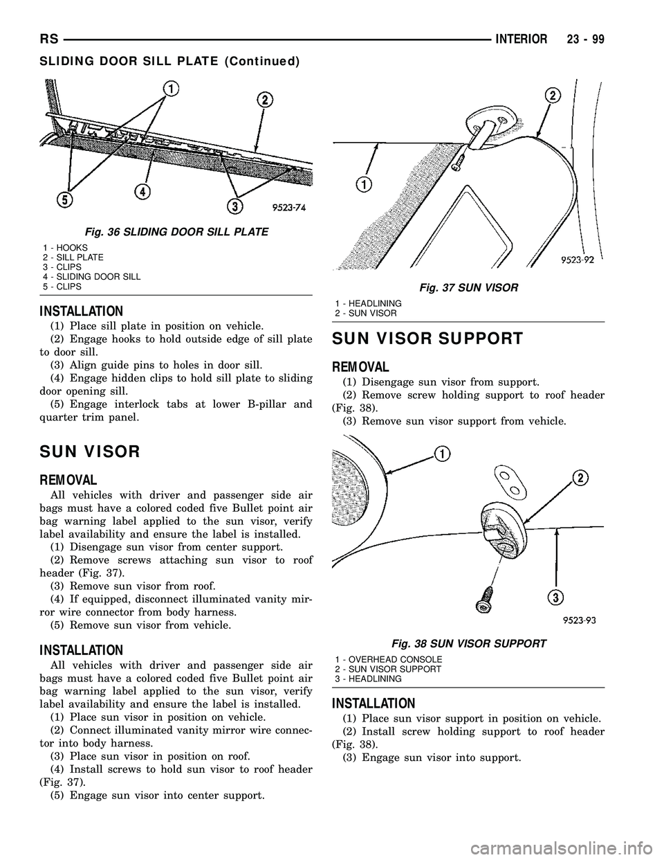
(1) Place sill plate in position on vehicle.
(2) Engage hooks to hold outside edge of sill plate
to door sill.
(3) Align guide pins to holes in door sill.
(4) Engage hidden clips to hold sill plate to sliding
door opening sill.
(5) Engage interlock tabs at lower B-pillar and
quarter trim panel.
SUN VISOR
REMOVAL
All vehicles with driver and passenger side air
bags must have a colored coded five Bullet point air
bag warning label applied to the sun visor, verify
label availability and ensure the label is installed.
(1) Disengage sun visor from center support.
(2) Remove screws attaching sun visor to roof
header (Fig. 37).
(3) Remove sun visor from roof.
(4) If equipped, disconnect illuminated vanity mir-
ror wire connector from body harness.
(5) Remove sun visor from vehicle.
INSTALLATION
All vehicles with driver and passenger side air
bags must have a colored coded five Bullet point air
bag warning label applied to the sun visor, verify
label availability and ensure the label is installed.
(1) Place sun visor in position on vehicle.
(2) Connect illuminated vanity mirror wire connec-
tor into body harness.
(3) Place sun visor in position on roof.
(4) Install screws to hold sun visor to roof header
(Fig. 37).
(5) Engage sun visor into center support.
SUN VISOR SUPPORT
REMOVAL
(1) Disengage sun visor from support.
(2) Remove screw holding support to roof header
(Fig. 38).
(3) Remove sun visor support from vehicle.
INSTALLATION
(1) Place sun visor support in position on vehicle.
(2) Install screw holding support to roof header
(Fig. 38).
(3) Engage sun visor into support.
Fig. 36 SLIDING DOOR SILL PLATE
1 - HOOKS
2 - SILL PLATE
3 - CLIPS
4 - SLIDING DOOR SILL
5 - CLIPS
Fig. 37 SUN VISOR
1 - HEADLINING
2 - SUN VISOR
Fig. 38 SUN VISOR SUPPORT
1 - OVERHEAD CONSOLE
2 - SUN VISOR SUPPORT
3 - HEADLINING
RSINTERIOR23-99
SLIDING DOOR SILL PLATE (Continued)
Page 1920 of 2339
INSTALLATION
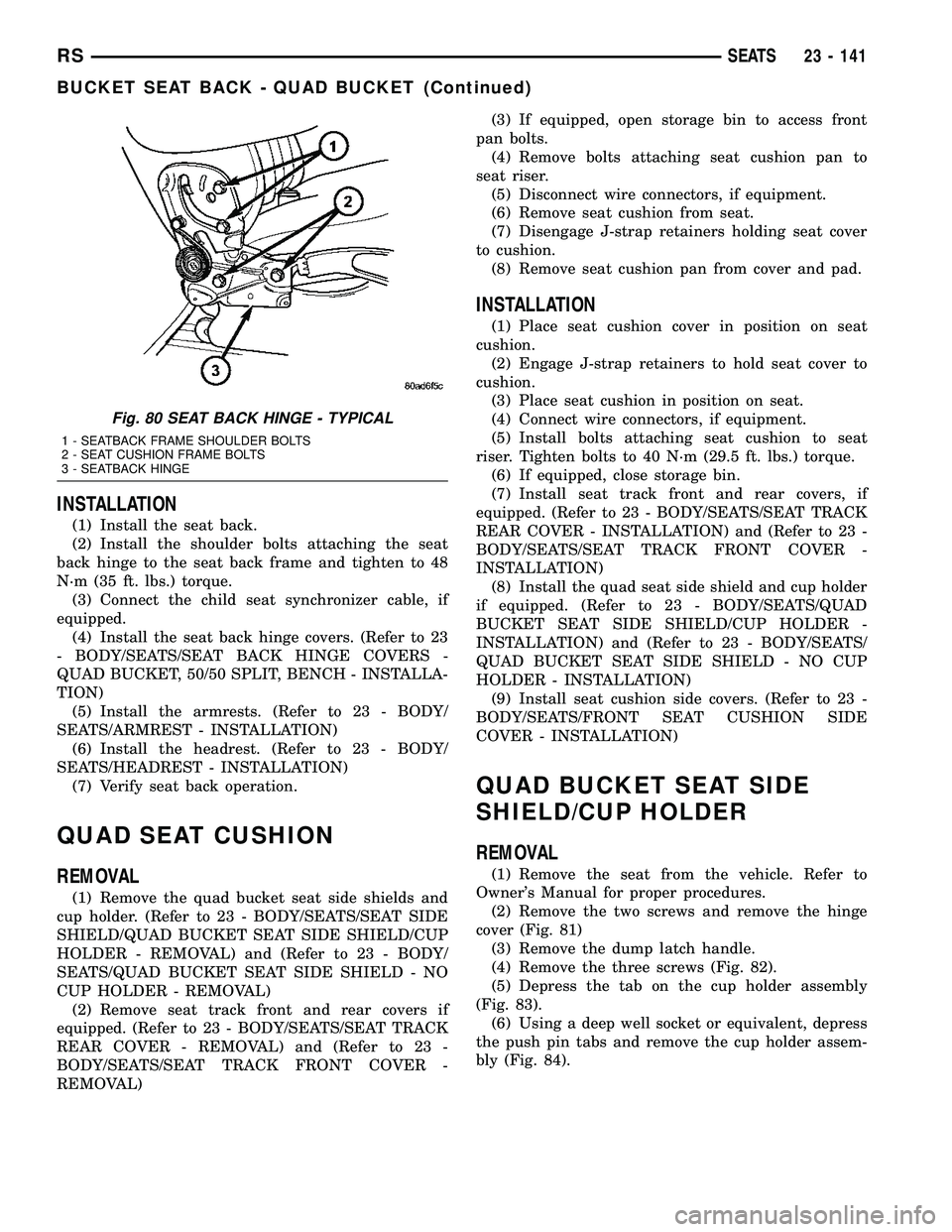
(1) Install the seat back.
(2) Install the shoulder bolts attaching the seat
back hinge to the seat back frame and tighten to 48
N´m (35 ft. lbs.) torque.
(3) Connect the child seat synchronizer cable, if
equipped.
(4) Install the seat back hinge covers. (Refer to 23
- BODY/SEATS/SEAT BACK HINGE COVERS -
QUAD BUCKET, 50/50 SPLIT, BENCH - INSTALLA-
TION)
(5) Install the armrests. (Refer to 23 - BODY/
SEATS/ARMREST - INSTALLATION)
(6) Install the headrest. (Refer to 23 - BODY/
SEATS/HEADREST - INSTALLATION)
(7) Verify seat back operation.
QUAD SEAT CUSHION
REMOVAL
(1) Remove the quad bucket seat side shields and
cup holder. (Refer to 23 - BODY/SEATS/SEAT SIDE
SHIELD/QUAD BUCKET SEAT SIDE SHIELD/CUP
HOLDER - REMOVAL) and (Refer to 23 - BODY/
SEATS/QUAD BUCKET SEAT SIDE SHIELD - NO
CUP HOLDER - REMOVAL)
(2) Remove seat track front and rear covers if
equipped. (Refer to 23 - BODY/SEATS/SEAT TRACK
REAR COVER - REMOVAL) and (Refer to 23 -
BODY/SEATS/SEAT TRACK FRONT COVER -
REMOVAL)(3) If equipped, open storage bin to access front
pan bolts.
(4) Remove bolts attaching seat cushion pan to
seat riser.
(5) Disconnect wire connectors, if equipment.
(6) Remove seat cushion from seat.
(7) Disengage J-strap retainers holding seat cover
to cushion.
(8) Remove seat cushion pan from cover and pad.
INSTALLATION
(1) Place seat cushion cover in position on seat
cushion.
(2) Engage J-strap retainers to hold seat cover to
cushion.
(3) Place seat cushion in position on seat.
(4) Connect wire connectors, if equipment.
(5) Install bolts attaching seat cushion to seat
riser. Tighten bolts to 40 N´m (29.5 ft. lbs.) torque.
(6) If equipped, close storage bin.
(7) Install seat track front and rear covers, if
equipped. (Refer to 23 - BODY/SEATS/SEAT TRACK
REAR COVER - INSTALLATION) and (Refer to 23 -
BODY/SEATS/SEAT TRACK FRONT COVER -
INSTALLATION)
(8) Install the quad seat side shield and cup holder
if equipped. (Refer to 23 - BODY/SEATS/QUAD
BUCKET SEAT SIDE SHIELD/CUP HOLDER -
INSTALLATION) and (Refer to 23 - BODY/SEATS/
QUAD BUCKET SEAT SIDE SHIELD - NO CUP
HOLDER - INSTALLATION)
(9) Install seat cushion side covers. (Refer to 23 -
BODY/SEATS/FRONT SEAT CUSHION SIDE
COVER - INSTALLATION)
QUAD BUCKET SEAT SIDE
SHIELD/CUP HOLDER
REMOVAL
(1) Remove the seat from the vehicle. Refer to
Owner's Manual for proper procedures.
(2) Remove the two screws and remove the hinge
cover (Fig. 81)
(3) Remove the dump latch handle.
(4) Remove the three screws (Fig. 82).
(5) Depress the tab on the cup holder assembly
(Fig. 83).
(6) Using a deep well socket or equivalent, depress
the push pin tabs and remove the cup holder assem-
bly (Fig. 84).
Fig. 80 SEAT BACK HINGE - TYPICAL
1 - SEATBACK FRAME SHOULDER BOLTS
2 - SEAT CUSHION FRAME BOLTS
3 - SEATBACK HINGE
RSSEATS23 - 141
BUCKET SEAT BACK - QUAD BUCKET (Continued)
Page 1928 of 2339
PLASTIC GROCERY BAG
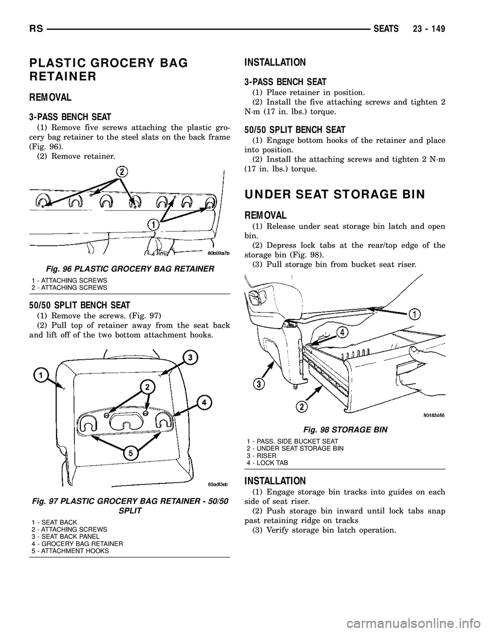
RETAINER
REMOVAL
3-PASS BENCH SEAT
(1) Remove five screws attaching the plastic gro-
cery bag retainer to the steel slats on the back frame
(Fig. 96).
(2) Remove retainer.
50/50 SPLIT BENCH SEAT
(1) Remove the screws. (Fig. 97)
(2) Pull top of retainer away from the seat back
and lift off of the two bottom attachment hooks.
INSTALLATION
3-PASS BENCH SEAT
(1) Place retainer in position.
(2) Install the five attaching screws and tighten 2
N´m (17 in. lbs.) torque.
50/50 SPLIT BENCH SEAT
(1) Engage bottom hooks of the retainer and place
into position.
(2) Install the attaching screws and tighten 2 N´m
(17 in. lbs.) torque.
UNDER SEAT STORAGE BIN
REMOVAL
(1) Release under seat storage bin latch and open
bin.
(2) Depress lock tabs at the rear/top edge of the
storage bin (Fig. 98).
(3) Pull storage bin from bucket seat riser.
INSTALLATION
(1) Engage storage bin tracks into guides on each
side of seat riser.
(2) Push storage bin inward until lock tabs snap
past retaining ridge on tracks
(3) Verify storage bin latch operation.
Fig. 96 PLASTIC GROCERY BAG RETAINER
1 - ATTACHING SCREWS
2 - ATTACHING SCREWS
Fig. 97 PLASTIC GROCERY BAG RETAINER - 50/50
SPLIT
1 - SEAT BACK
2 - ATTACHING SCREWS
3 - SEAT BACK PANEL
4 - GROCERY BAG RETAINER
5 - ATTACHMENT HOOKS
Fig. 98 STORAGE BIN
1 - PASS. SIDE BUCKET SEAT
2 - UNDER SEAT STORAGE BIN
3 - RISER
4 - LOCK TAB
RSSEATS23 - 149