2005 CHRYSLER VOYAGER wheel size
[x] Cancel search: wheel sizePage 1440 of 2339
(17) With the wheels pointed approximately
STRAIGHT-AHEAD, align the intermediate shaft
with the steering column coupler. Assemble the steer-
ing column shaft coupler onto the steering gear inter-
mediate coupler (Fig. 2). Install steering column
coupler to intermediate shaft retaining pinch bolt.
Tighten the pinch bolt nut to a torque of 28 N´m (250
in. lbs.).
(18) Remove the steering wheel holding tool.
(19) Fill and bleed the power steering system
using the Power Steering Pump Initial Operation
Procedure. (Refer to 19 - STEERING/PUMP - STAN-
DARD PROCEDURE)
(20) Inspect system for leaks.
(21) Adjust front toe (Refer to 2 - SUSPENSION/
WHEEL ALIGNMENT - STANDARD PROCEDURE).
INSTALLATION - RHD GEAR
(1) Install the steering gear up in the front sus-
pension cradle crossmember, leaving room to install
intermediate coupler.
(2) Start the roll pin into the intermediate coupler
before installing coupler on steering gear shaft. Start
roll pin into coupler, using a hammer and tapping it
into the coupler. Then install the intermediate cou-
pler on the shaft of the steering gear.
(3) Install Remover/Installer Special Tool 6831A
through the center of the roll pin, securing it with
the knurled nut (Fig. 12). Hold threaded rod station-
ary while turning nut. This will pull the roll pin into
the intermediate coupler.
(4) Install power steering gear on the front suspen-
sion cradle. Install the 2 steering gear mounting
bolts and nuts. Tighten the M-14 size steering gear
to suspension cradle mounting bolt to a torque of 183
N´m (135 ft. lbs.). Tighten the M-12 size steering
gear to suspension cradle mounting bolt to a torque
of 95 N´m (70 ft. lbs.).
CAUTION: Proper torque on the steering gear to
suspension cradle mounting bolts is very impor-
tant.
(5) Install the heat shield on the steering gear
(Fig. 10).
(6) Attach the power steering fluid pressure and
return hoses to the proper fittings on the steering
gear (Fig. 10). Do not fully tighten the fittings at this
time.
(7) Install the routing clamp with the bolt securing
the power steering fluid hoses to the rear of the cra-
dle crossmember (Fig. 11).
(8) Using a crowfoot wrench on a torque wrench,
tighten the power steering fluid hose tube nuts at the
gear to a torque of 31 N´m (275 in. lbs.).
(9) Install tie rod end into steering knuckle. Start
tie rod end to steering knuckle attaching nut ontostud of tie rod end. While holding stud of tie rod end
stationary using a socket (Fig. 4), tighten tie rod end
to steering knuckle attaching nut. Then using a
crowfoot and socket (Fig. 13), tighten the tie rod end
attaching nut to a torque of 75 N´m (55 ft. lbs.).
(10) If the vehicle is equipped with All-Wheel-
Drive, install the power transfer unit (Refer to 21 -
TRANSMISSION/TRANSAXLE/POWER TRANSFER
UNIT - INSTALLATION).
CAUTION: Proper torque on the cradle reinforce-
ment to suspension cradle mounting bolts is very
important.
(11) Install the reinforcement on the front suspen-
sion cradle crossmember and install the bolts attach-
ing the reinforcement to the cradle crossmember
(Fig. 6). Tighten the M-14 size bolts to a torque of
163 N´m (120 ft. lbs.). Tighten the M-12 size bolts to
a torque of 108 N´m (80 ft. lbs.).
(12) Install the lower control arm rear bushing
retainer bolts through reinforcement on each side of
each lower control arm rear bushing. Tighten bolts to
a torque of 61 N´m (45 ft. lbs.).
(13) Install the two bolts and bushings attaching
the reinforcement and rear of cradle crossmember to
body of vehicle (Fig. 6). Tighten bolts to a torque of
163 N´m (120 ft. lbs.).
(14) If power steering cooler equipped, install the
previously disconnected power steering cooler hose on
the cooler. Install the clamp.
(15) If power steering cooler equipped, install the
power steering fluid cooler on the cradle crossmem-
ber reinforcement (Fig. 3). Install the mounting bolts
and tighten to 11 N´m (100 in. lbs.).
(16) Install the front tire and wheel assemblies on
vehicle. Install the wheel mounting lug nuts and
tighten to a torque to 135 N´m (100 ft. lbs.).
(17) Lower the vehicle to a level were the interior
of vehicle is accessible (keeping tires off the ground).
(18) With the wheels pointed approximately
STRAIGHT-AHEAD, align the intermediate shaft
with the steering column coupler. Assemble the steer-
ing column shaft coupler onto the steering gear inter-
mediate coupler (Fig. 2). Install steering column
coupler to intermediate shaft retaining pinch bolt.
Tighten the pinch bolt nut to a torque of 28 N´m (250
in. lbs.).
(19) Remove the steering wheel holding tool.
(20) Perform the POWER STEERING PUMP INI-
TIAL OPERATION procedure to properly fill and
bleed the power steering system. (Refer to 19 -
STEERING/PUMP - STANDARD PROCEDURE)
(21) Inspect for leaks.
(22) Adjust front wheel toe (Refer to 2 - SUSPEN-
SION/WHEEL ALIGNMENT - STANDARD PROCE-
DURE).
RSGEAR19-33
GEAR (Continued)
Page 1768 of 2339
CAUTION
CAUTION: The use of tire sealants is strictly prohib-
ited for vehicles equipped with the Tire Pressure
Monitoring system. Tire sealants can clog tire pres-
sure sensors.
CAUTION: Tire pressure sensor valve stem caps
and cores are specially designed for the sensors.
Due to risk of corrosion, do not use a standard
valve stem cap or core in a tire pressure sensor in
place of the original equipment style sensor cap
and core.
CAUTION: Do not attempt to install a tire pressure
sensor in a steel wheel or aftermarket wheel. Use
tire pressure sensors in original style factory
wheels only.
NOTE: TPM thresholds have been established for
the original tire size equipped on the vehicle. Use
original size tires only to maintain system accuracy.
DIAGNOSIS AND TESTING - TIRE PRESSURE
SENSOR
NOTE: Tire pressure may increase from 2 to 6 psi
(14 to 41 kPa) during normal driving conditions. Do
NOT reduce this normal pressure build up.
If a fault in the system is detected, always check
air pressure in the tires first with a known accurate
air gauge and correct the inflation pressure. If any
tire is low, inspectallthe tires.
If the gauge-read pressure in the tires does not
indicate a tire pressure issue, refer to the appropri-
ate diagnostic information.
REMOVAL
(1) Remove tire and wheel assembly from vehicle.
(Refer to 22 - TIRES/WHEELS - REMOVAL)
CAUTION: The cap used on this valve stem con-
tains an O-ring seal to prevent contamination and
moisture from entering the valve stem. Retain this
valve stem cap for reuse. Do not substitute a regu-
lar valve stem cap in its place.
CAUTION: The valve stem used on this vehicle is
made of aluminum and the core is nickel plated
brass. The original valve stem core must be rein-
stalled and not substituted with a valve stem core
made of a different material. This is required to pre-
vent corrosion in the valve stem caused by the dif-
ferent metals.(2) Dismount tire from wheel following tire
changer manufacturers instructions while paying
special attention to the following to avoid damaging
the pressure sensor:
(a) When breaking the tire bead loose from the
wheel rim, avoid using the Bead Breaker in the
area of the sensor. That includes both front and
rear beads of the tire.
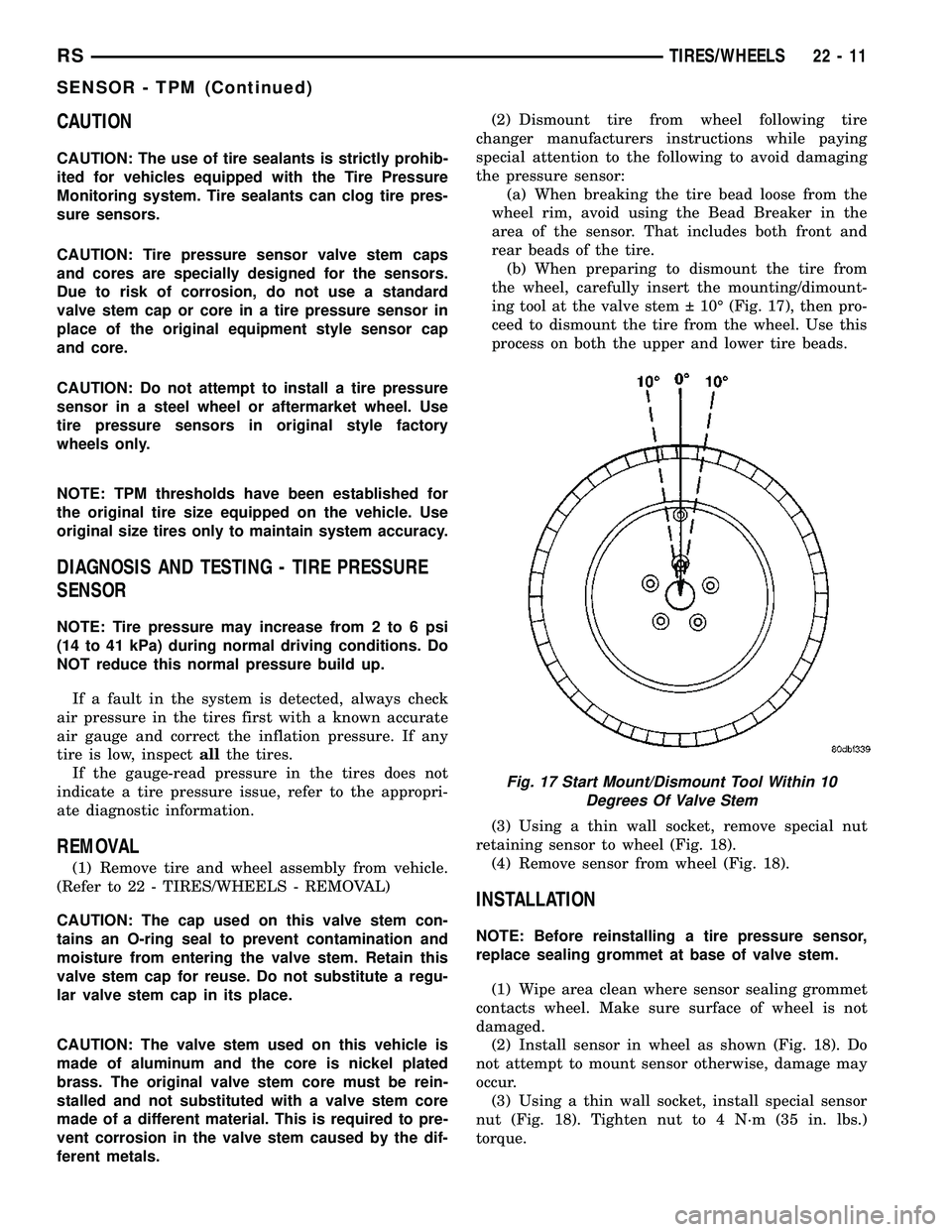
(b) When preparing to dismount the tire from
the wheel, carefully insert the mounting/dimount-
ing tool at the valve stem 10É (Fig. 17), then pro-
ceed to dismount the tire from the wheel. Use this
process on both the upper and lower tire beads.
(3) Using a thin wall socket, remove special nut
retaining sensor to wheel (Fig. 18).
(4) Remove sensor from wheel (Fig. 18).
INSTALLATION
NOTE: Before reinstalling a tire pressure sensor,
replace sealing grommet at base of valve stem.
(1) Wipe area clean where sensor sealing grommet
contacts wheel. Make sure surface of wheel is not
damaged.
(2) Install sensor in wheel as shown (Fig. 18). Do
not attempt to mount sensor otherwise, damage may
occur.
(3) Using a thin wall socket, install special sensor
nut (Fig. 18). Tighten nut to 4 N´m (35 in. lbs.)
torque.
Fig. 17 Start Mount/Dismount Tool Within 10
Degrees Of Valve Stem
RSTIRES/WHEELS22-11
SENSOR - TPM (Continued)
Page 1770 of 2339
TIRES
DESCRIPTION
DESCRIPTION - TIRE
Tires are designed and engineered for each specific
vehicle. They provide the best overall performance
for normal operation. The ride and handling charac-
teristics match the vehicle's requirements. With
proper care they will give excellent reliability, trac-
tion, skid resistance, and tread life.
Driving habits have more effect on tire life than
any other factor. Careful drivers will obtain, in most
cases, much greater mileage than severe use or care-
less drivers. A few of the driving habits which will
shorten the life of any tire are:
²Rapid acceleration
²Severe application of brakes
²High-speed driving
²Taking turns at excessive speeds
²Striking curbs and other obstacles
²Operating vehicle with over or under inflated
tire pressures
Radial ply tires are more prone to irregular tread
wear. It is important to follow the tire rotation inter-
val shown in the section on Tire Rotation. This will
help to achieve a greater tread-life potential.
TIRE IDENTIFICATION
Tire type, size, load index and speed rating are
encoded in the letters and numbers imprinted on the
side wall of the tire. Refer to the Tire Identification
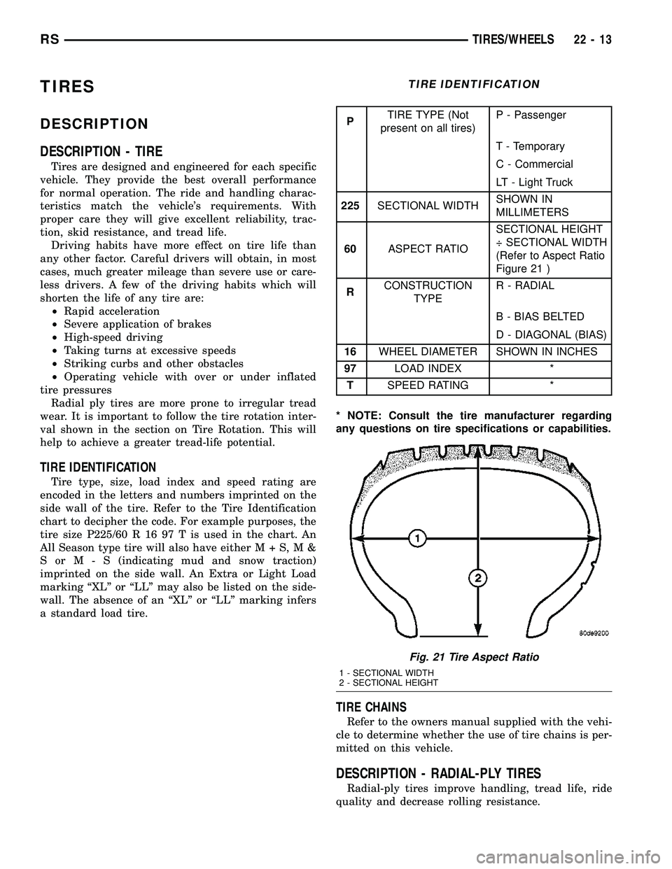
chart to decipher the code. For example purposes, the
tire size P225/60 R 16 97 T is used in the chart. An
All Season type tire will also have eitherM+S,M&
SorM-S(indicating mud and snow traction)
imprinted on the side wall. An Extra or Light Load
marking ªXLº or ªLLº may also be listed on the side-
wall. The absence of an ªXLº or ªLLº marking infers
a standard load tire.
TIRE IDENTIFICATION
PTIRE TYPE (Not
present on all tires)P - Passenger
T - Temporary
C - Commercial
LT - Light Truck
225SECTIONAL WIDTHSHOWN IN
MILLIMETERS
60ASPECT RATIOSECTIONAL HEIGHT
÷ SECTIONAL WIDTH
(Refer to Aspect Ratio
Figure 21 )
RCONSTRUCTION
TYPER - RADIAL
B - BIAS BELTED
D - DIAGONAL (BIAS)
16WHEEL DIAMETER SHOWN IN INCHES
97LOAD INDEX *
TSPEED RATING *
* NOTE: Consult the tire manufacturer regarding
any questions on tire specifications or capabilities.
TIRE CHAINS
Refer to the owners manual supplied with the vehi-
cle to determine whether the use of tire chains is per-
mitted on this vehicle.
DESCRIPTION - RADIAL-PLY TIRES
Radial-ply tires improve handling, tread life, ride
quality and decrease rolling resistance.
Fig. 21 Tire Aspect Ratio
1 - SECTIONAL WIDTH
2 - SECTIONAL HEIGHT
RSTIRES/WHEELS22-13
Page 1771 of 2339
Radial-ply tires must always be used in sets of four
and under no circumstances should they be used on
the front only. It is recommended that tires from dif-
ferent manufacturers NOT be mixed. They may be
mixed with a temporary spare tire when necessary. A
maximum speed of 80 km/h (50 mph) is recom-
mended while a temporary spare is in use.
Radial-ply tires have the same load-carrying capac-
ity as other types of tires of the same size. They also
use the same recommended inflation pressures.
DESCRIPTION - REPLACEMENT TIRES
WARNING: FAILURE TO EQUIP THE VEHICLE WITH
TIRES HAVING ADEQUATE SPEED CAPABILITY
CAN RESULT IN SUDDEN TIRE FAILURE.
WARNING: IN ORDER TO MAINTAIN THE SPEED
CAPABILITY OF THE VEHICLE, REPLACEMENT
TIRES MUST HAVE SPEED RATINGS EQUAL TO OR
HIGHER THAN THOSE FITTED TO THE VEHICLE AS
ORIGINAL EQUIPMENT. IF TIRES WITH LOWER
SPEED RATINGS ARE FITTED, THE VEHICLE'S
HANDLING MAY BE AFFECTED AND THE SPEED
CAPABILITY OF THE VEHICLE MAY BE LOWERED
TO THE MAXIMUM SPEED CAPABILITY OF THE
REPLACEMENT TIRES. TO AVOID AN ACCIDENT
RESULTING IN SEVERE OR FATAL INJURY, CON-
SULT THE TIRE MANUFACTURER IN REGARDS TO
MAXIMUM SPEED RATINGS.
It is recommended that tires equivalent to the orig-
inal equipment tires be used when replacement is
needed.
Failure to use equivalent replacement tires may
adversely affect the safety and handling of the vehi-
cle.
The original equipment tires provide a proper com-
bination of many characteristics such as:
²Ride
²Noise
²Handling
²Durability
²Tread life²Traction
²Rolling resistance
²Speed capability
The use of tires smaller than the minimum tire
size approved for the vehicle can result in tire over-
loading and failure.
Use tires that have the approved load rating for
the vehicle and never overload them. Failure to equip
the vehicle with tires having adequate speed capabil-
ity can result in sudden tire failure and loss of vehi-
cle control.
The use of oversize tires may cause interference
with vehicle components. Under extremes of suspen-
sion and steering travel, interference with vehicle
components may cause tire damage.
DESCRIPTION - SPARE TIRE (TEMPORARY)
The temporary (convenience) spare tire is designed
for emergency use only. The original tire should be
repaired and reinstalled, or replaced with a new, at
the first opportunity.
The temporary (convenience) spare tire should be
inflated to the pressure listed on its sidewall. Do not
exceed speeds of 80 km/h (50 mph) when the tempo-
rary spare tire is in use on the vehicle. Refer to the
Owner's Manual for more details.
DIAGNOSIS AND TESTING
DIAGNOSIS AND TESTING - TIRE NOISE
Unusual tire noise can be associated with tire and
wheel vibration or irregular tire wear. For vibration,
(Refer to 22 - TIRES/WHEELS - DIAGNOSIS AND
TESTING). For irregular tire wear, (Refer to 22 -
TIRES/WHEELS/TIRES - DIAGNOSIS AND TEST-
ING).
DIAGNOSIS AND TESTING - TIRE/VEHICLE
LEAD
Use the following Vehicle Lead Diagnosis And Cor-
rection Chart to diagnose and correct a vehicle lead
or drift problem.
22 - 14 TIRES/WHEELSRS
TIRES (Continued)
Page 1776 of 2339
DIAGNOSIS AND TESTING - WHEEL
INSPECTION
Inspect wheels for:
²Excessive runout
²Dents, cracks or irregular bends
²Damaged wheel stud (lug) holes
²Air Leaks
NOTE: Do not attempt to repair a wheel by hammer-
ing, heating or welding.
If a wheel is damaged, an original equipment
replacement wheel should be used. When obtaining
replacement wheels, they must be equivalent in load
carrying capacity. The diameter, width, offset, pilot
hole and bolt circle of the wheel should be the same
as the original wheel.
WARNING: FAILURE TO USE EQUIVALENT
REPLACEMENT WHEELS MAY ADVERSELY
AFFECT THE SAFETY AND HANDLING OF THE
VEHICLE.
WARNING: REPLACEMENT WITH USED WHEELS IS
NOT RECOMMENDED. THE SERVICE HISTORY OF
THE WHEEL MAY HAVE INCLUDED SEVERE TREAT-
MENT OR VERY HIGH MILEAGE. THE RIM COULD
FAIL WITHOUT WARNING.
CLEANING
WHEEL AND WHEEL TRIM CARE
All wheels and wheel trim, especially aluminum
and chrome plated, should be cleaned regularly using
mild soap and water to maintain their luster and to
prevent corrosion. Wash them with the same soap
solution recommended for the body of the vehicle.
When cleaning extremely dirty wheels, care must
be taken in the selection of tire and wheel cleaning
chemicals and equipment to prevent damage to the
wheels. MopartWheel Treatment or MopartChrome
Cleaner is recommended. Any of the ªDO NOT USEº
items listed below can damage wheels and wheel
trim.DO NOT USE:
²Any abrasive cleaner
²Any abrasive cleaning pad (such as steel wool)
or abrasive brush
²Any cleaner that contains an acid which can
react with and discolor the chrome surface.Many
wheel cleaners contain acids that can harm the
wheel surface.
²Oven cleaner
²A car wash that uses carbide-tipped wheel clean-
ing brushes or acidic solutions.
SPECIFICATIONS
WHEEL
SPECIFICATIONS
DESCRIPTION SPECIFICATION
Wheel Mounting (Lug)
Nut Hex Size19 mm
Wheel Mounting Stud
SizeM12 x 1.5 mm
TORQUE SPECIFICATIONS
DESCRIPTION N´mFt.
Lbs.In.
Lbs.
TPM Sensor Mounting Nut 4 Ð 35
Wheel Mounting (Lug ) Nut 135 100 Ð
WHEEL COVER
DESCRIPTION
This vehicle uses a bolt-on type wheel cover (Fig.
29).
This bolt-on wheel cover cannot be removed from
the wheel until three of the five wheel mounting nuts
shown are removed (Fig. 29). The bolt-on wheel cover
can then be removed with the remaining two wheel
nuts tightened in place.
REMOVAL
(1) Noting the location of the valve stem in rela-
tionship to the wheel mounting nuts, remove the
three wheel mounting nuts securing the wheel cover
to the wheel and hub (Fig. 29).
CAUTION: When removing the wheel cover, do not
pry the wheel cover from the wheel. This can result
in damage to the wheel cover. The wheel cover is
removed by pulling it off the wheel by hand.
RSTIRES/WHEELS22-19
WHEELS (Continued)
Page 2232 of 2339
REMOVAL
WARNING: ON VEHICLES EQUIPPED WITH AIR-
BAGS, DISABLE THE AIRBAG SYSTEM BEFORE
ATTEMPTING ANY STEERING WHEEL, STEERING
COLUMN, OR INSTRUMENT PANEL COMPONENT
DIAGNOSIS OR SERVICE. DISCONNECT AND ISO-
LATE THE BATTERY NEGATIVE (GROUND) CABLE,
THEN WAIT TWO MINUTES FOR THE AIRBAG SYS-
TEM CAPACITOR TO DISCHARGE BEFORE PER-
FORMING FURTHER DIAGNOSIS OR SERVICE. THIS
IS THE ONLY SURE WAY TO DISABLE THE AIRBAG
SYSTEM. FAILURE TO TAKE THE PROPER PRE-
CAUTIONS COULD RESULT IN ACCIDENTAL AIR-
BAG DEPLOYMENT AND POSSIBLE PERSONAL
INJURY.
(1) Remove the HVAC housing (Refer to 24 -
HEATING & AIR CONDITIONING/DISTRIBUTION/
HVAC HOUSING - REMOVAL).
(2) Disassemble the HVAC housing to access the
evaporator (Refer to 24 - HEATING & AIR CONDI-
TIONING/DISTRIBUTION/HVAC HOUSING - DIS-
ASSEMBLY).
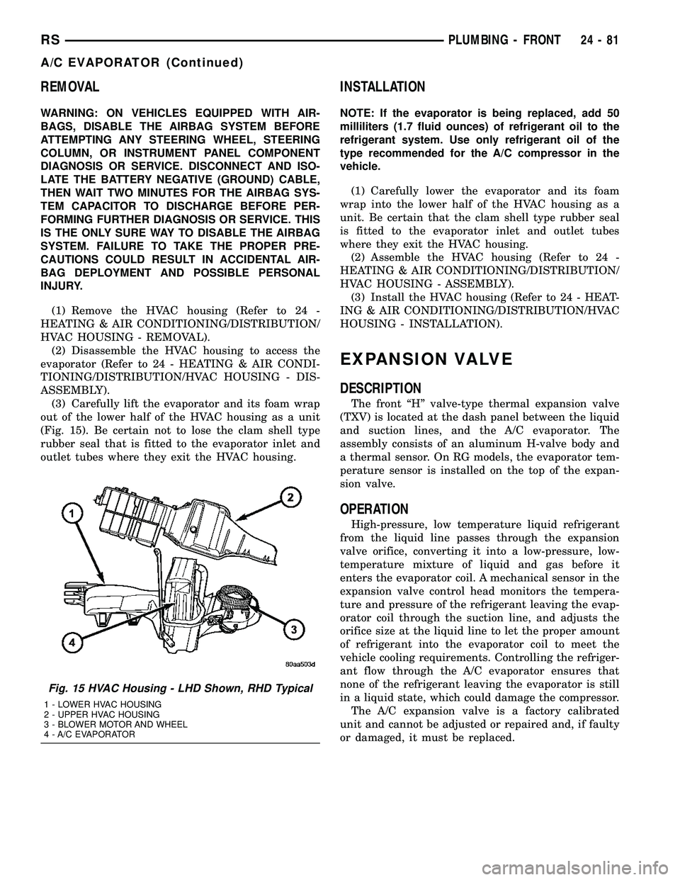
(3) Carefully lift the evaporator and its foam wrap
out of the lower half of the HVAC housing as a unit
(Fig. 15). Be certain not to lose the clam shell type
rubber seal that is fitted to the evaporator inlet and
outlet tubes where they exit the HVAC housing.
INSTALLATION
NOTE: If the evaporator is being replaced, add 50
milliliters (1.7 fluid ounces) of refrigerant oil to the
refrigerant system. Use only refrigerant oil of the
type recommended for the A/C compressor in the
vehicle.
(1) Carefully lower the evaporator and its foam
wrap into the lower half of the HVAC housing as a
unit. Be certain that the clam shell type rubber seal
is fitted to the evaporator inlet and outlet tubes
where they exit the HVAC housing.
(2) Assemble the HVAC housing (Refer to 24 -
HEATING & AIR CONDITIONING/DISTRIBUTION/
HVAC HOUSING - ASSEMBLY).
(3) Install the HVAC housing (Refer to 24 - HEAT-
ING & AIR CONDITIONING/DISTRIBUTION/HVAC
HOUSING - INSTALLATION).
EXPANSION VALVE
DESCRIPTION
The front ªHº valve-type thermal expansion valve
(TXV) is located at the dash panel between the liquid
and suction lines, and the A/C evaporator. The
assembly consists of an aluminum H-valve body and
a thermal sensor. On RG models, the evaporator tem-
perature sensor is installed on the top of the expan-
sion valve.
OPERATION
High-pressure, low temperature liquid refrigerant
from the liquid line passes through the expansion
valve orifice, converting it into a low-pressure, low-
temperature mixture of liquid and gas before it
enters the evaporator coil. A mechanical sensor in the
expansion valve control head monitors the tempera-
ture and pressure of the refrigerant leaving the evap-
orator coil through the suction line, and adjusts the
orifice size at the liquid line to let the proper amount
of refrigerant into the evaporator coil to meet the
vehicle cooling requirements. Controlling the refriger-
ant flow through the A/C evaporator ensures that
none of the refrigerant leaving the evaporator is still
in a liquid state, which could damage the compressor.
The A/C expansion valve is a factory calibrated
unit and cannot be adjusted or repaired and, if faulty
or damaged, it must be replaced.
Fig. 15 HVAC Housing - LHD Shown, RHD Typical
1 - LOWER HVAC HOUSING
2 - UPPER HVAC HOUSING
3 - BLOWER MOTOR AND WHEEL
4 - A/C EVAPORATOR
RSPLUMBING - FRONT24-81
A/C EVAPORATOR (Continued)