2005 CHRYSLER VOYAGER Comfort
[x] Cancel search: ComfortPage 1174 of 2339
8W-97 POWER DISTRIBUTION SYSTEM
TABLE OF CONTENTS
page page
POWER DISTRIBUTION SYSTEM
DESCRIPTION..........................1
OPERATION............................1
SPECIAL TOOLS
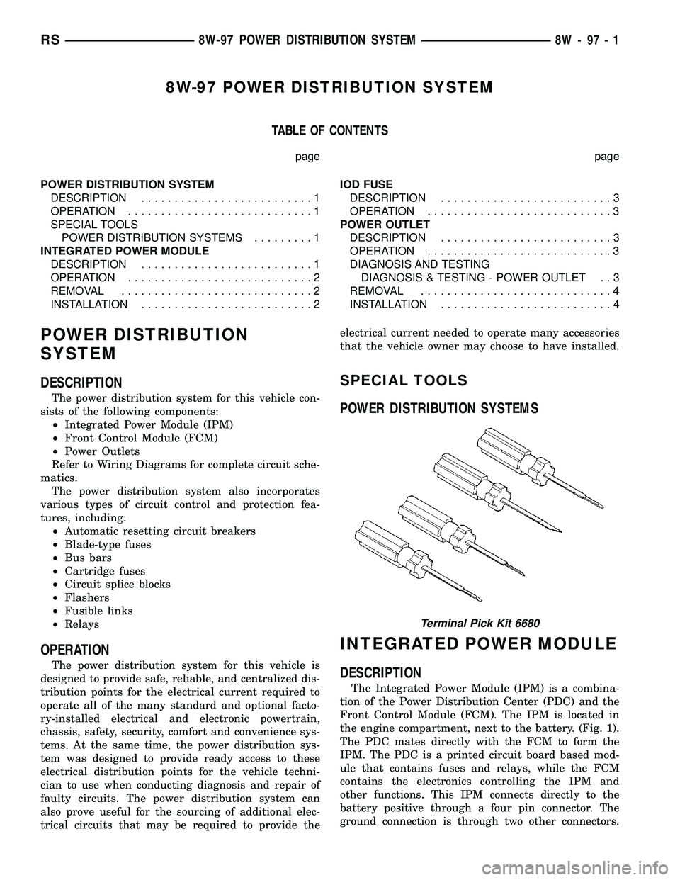
POWER DISTRIBUTION SYSTEMS.........1
INTEGRATED POWER MODULE
DESCRIPTION..........................1
OPERATION............................2
REMOVAL.............................2
INSTALLATION..........................2IOD FUSE
DESCRIPTION..........................3
OPERATION............................3
POWER OUTLET
DESCRIPTION..........................3
OPERATION............................3
DIAGNOSIS AND TESTING
DIAGNOSIS & TESTING - POWER OUTLET . . 3
REMOVAL.............................4
INSTALLATION..........................4
POWER DISTRIBUTION
SYSTEM
DESCRIPTION
The power distribution system for this vehicle con-
sists of the following components:
²Integrated Power Module (IPM)
²Front Control Module (FCM)
²Power Outlets
Refer to Wiring Diagrams for complete circuit sche-
matics.
The power distribution system also incorporates
various types of circuit control and protection fea-
tures, including:
²Automatic resetting circuit breakers
²Blade-type fuses
²Bus bars
²Cartridge fuses
²Circuit splice blocks
²Flashers
²Fusible links
²Relays
OPERATION
The power distribution system for this vehicle is
designed to provide safe, reliable, and centralized dis-
tribution points for the electrical current required to
operate all of the many standard and optional facto-
ry-installed electrical and electronic powertrain,
chassis, safety, security, comfort and convenience sys-
tems. At the same time, the power distribution sys-
tem was designed to provide ready access to these
electrical distribution points for the vehicle techni-
cian to use when conducting diagnosis and repair of
faulty circuits. The power distribution system can
also prove useful for the sourcing of additional elec-
trical circuits that may be required to provide theelectrical current needed to operate many accessories
that the vehicle owner may choose to have installed.
SPECIAL TOOLS
POWER DISTRIBUTION SYSTEMS
INTEGRATED POWER MODULE
DESCRIPTION
The Integrated Power Module (IPM) is a combina-
tion of the Power Distribution Center (PDC) and the
Front Control Module (FCM). The IPM is located in
the engine compartment, next to the battery. (Fig. 1).
The PDC mates directly with the FCM to form the
IPM. The PDC is a printed circuit board based mod-
ule that contains fuses and relays, while the FCM
contains the electronics controlling the IPM and
other functions. This IPM connects directly to the
battery positive through a four pin connector. The
ground connection is through two other connectors.
Terminal Pick Kit 6680
RS8W-97 POWER DISTRIBUTION SYSTEM8W-97-1
Page 1948 of 2339
SUNROOF
TABLE OF CONTENTS
page page
SUNROOF
DESCRIPTION........................169
DIAGNOSIS AND TESTING
SUNROOF DIAGNOSIS AND TESTING....169
DRAIN TUBE
REMOVAL............................172
INSTALLATION........................172
GLASS PANEL
REMOVAL............................173
INSTALLATION........................173
ADJUSTMENTS
SUNROOF GLASS PANEL ADJUSTMENT . . 173
SUNROOF ASSEMBLY
REMOVAL............................173
INSTALLATION........................173
SUNSHADE
REMOVAL............................173INSTALLATION........................173
WIND DEFLECTOR
REMOVAL............................174
INSTALLATION........................174
WATER CHANNEL
REMOVAL............................174
INSTALLATION........................174
SUNROOF MOTOR
REMOVAL............................174
INSTALLATION........................174
ADJUSTMENTS
ADJUSTMENT.......................175
SUNROOF SWITCH
REMOVAL............................176
INSTALLATION........................176
SUNROOF
DESCRIPTION
WARNING: Keep fingers and other body parts out
of sunroof opening at all times.
The sun roof features consists of: (Fig. 1)
²Sun roof glass
²Sun roof sun shade
The sunroof power sliding glass panel and sun-
shade can be positioned anywhere along its travel,
rearward of glass panel front edge.
The sunroof is electrically operated from a switch
located in the overhead console. To operate the sun-
roof the ignition switch must be in the Accessory or
On/Run position. Both switchs are a rocker style
design that open or close the sunroof. When pressing
and releasing the open button once, the sunroof will
express open to the comfort stop and the wind deflec-
tor will raise. If the button is pressed a second time,
the sunroof will continue to open to full travel unless
the button is released, at which time it will stop in
that position. Pressing and holding the close button
will close the sunroof. If the close button is released
before the glass fully closes, the sunroof will stop in
that position. The vent switch operates in a similar
manor. The sunroof will also operate for up to fifteen
minutes after the ignition key is turned off for cus-
tomer comfort and convenance while parking.
DIAGNOSIS AND TESTING
SUNROOF DIAGNOSIS AND TESTING
Refer to Sunroof Diagnostic Chart for possible
causes. Before beginning sunroof diagnostics verify
that all other power accessories are in proper operat-
ing condition. If not, a common electrical problem
may exist. Refer to Wiring Diagrams, in this publica-
tion for circuit, splice and component descriptions.
Check the condition of the circuit protection (20 amp
circuit breaker in the Junction Block). Inspect all
wiring connector pins for proper engagement and
continuity. Check for battery voltage at the power
sunroof controller, refer to Wiring Diagrams, for cir-
cuit information. If battery voltage of more than 10
volts is detected at the controller, proceed with the
following tests (the controller will not operate at less
than 10 volts).
Before beginning diagnosis for wind noise or water
leaks, verify that the problem was not caused by
releasing the control switch before the sunroof was
fully closed. The sunroof module has a water-man-
agement system. If however, the sunroof glass is in a
partial closed position, high pressure water may be
forced beyond the water management system bound-
aries and onto the headlining.
RSSUNROOF23 - 169
Page 2154 of 2339
²a rotary adjustment knob for temperature.
²a rotary adjustment for fan speed control.
AUTOMATIC TEMPERATURE CONTROL
Two different automatic temperature control (ATC)
heating-A/C systems are available for this model
depending on the market.
The Dual-Zone ATC system allows the driver and
front occupants to each select individual comfort tem-
peratures.
The Three-Zone ATC system allows both the driver
and front occupants and the rear intermediate occu-
pants to select individual comfort temperatures.
NOTE: Individual comfort temperatures are the per-
ceived temperature level at the individual seating
areas, NOT the actual passenger compartment air
temperature.
The ATC system includes a particulate air filter.
The filter element is the same size as the A/C evap-
orator to ensure ample capacity. A door at the base of
the HVAC housing below the glove box provides easy
access to the filter element.
The ATC computer utilizes integrated circuitry and
information carried on the programmable communi-
cations interface (PCI) data bus network to monitor
many sensors and switch inputs throughout the vehi-
cle. In response to those inputs, the internal circuitry
and programming of the ATC computer allow it to
control electronic functions and features of the ATC
system. The inputs to the ATC computer are:
²Vehicle Speed/Engine RPM± The ATC com-
puter monitors engine rpm, vehicle speed and mani-
fold absolute pressure information from the
powertrain control module (PCM).
²Coolant Temperature± ATC computer moni-
tors coolant temperature received from the PCM and
converts it to degrees Fahrenheit.
²Ambient Temperature± ATC computer moni-
tors ambient temperature from the compass mini trip
computer (CMTC) and converts it to degrees Fahren-
heit.
²Engine Miscellaneous Sensor Status±ATC
computer monitors A/C disable information from the
PCM.
²Refrigerant Pressure± ATC computer moni-
tors barometric pressure, intake air temperature,
high side pressure and methanol content as broad-
cast by the PCM.
²Door Ajar Status± The ATC computer moni-
tors driver front door, passenger front door, left rear
door, right rear door and liftgate ajar information, as
identified by the body control module (BCM), to
determine if all in-car temperatures should be main-
tained.²Dimming± The ATC computer monitors dim-
ming status from the BCM to determine the required
level of brightness and will dim accordingly.
²Vehicle Odometer± The ATC computer moni-
tors the vehicle odometer information from the BCM
to prevent flashing the vacuum-flourescent (VF) dig-
ital display icons if the manual motor calibration or
manual cool down tests have failed. Flashing of the
display icons will cease when the vehicle odometer is
greater than 3 miles.
²English/Metric± The ATC computer monitors
the English/Metric information broadcast by the
CMTC. The set temp displays for both the front and
rear control heads will be set accordingly.
²Vehicle Identification Number± The ATC
computer monitors the last eight characters of the
VIN broadcast by the PCM and compares it to the
information stored in EEPROM. If it is different, the
new number will be stored over the old one and a
motor calibration shall be initiated.
²A/C System Information± The ATC computer
will send a message for evaporator temperature too
low, fan blower relay status, evaporator sensor fail-
ure, rear window defogger relay and A/C select.
FRONT CONTROL PANEL
The front A/C-heater control and integral computer
is mounted in the instrument panel and contains:
²a power button which allows the system to be
completely turned off. The display is blank when the
system is off.
²a rocker switch that selects a cool-down rate.
LO-AUTO or HI-AUTO are displayed when the sys-
tem is in automatic operation.
²three rocker switches that select comfort temper-
atures from 15É to 30É C (59É to 85É F), which are
shown in the VF digital display. If the set temp is 15É
C (59É F) and the down button is pressed, the set
temp value will become 13É C (55É F) but the display
will show LO. If the set temp is 29É C (85É F) and the
up button is pressed, the set temp value will become
32É C (90É F) but the display will show HIGH. Tem-
peratures can be displayed in either metric or Fahr-
enheit, which is controlled from the overhead console.
²an air conditioning button that allows the com-
pressor to be turned off. A Snowflake symbol is illu-
minated when air conditioning is on, whether under
manual or automatic control.
²an air recirculation button. A Recirculation sym-
bol appears in the display when the button is
pressed, or when the system exceeds 80 percent recir-
culated air under automatic control due to high air
conditioning demand.
²a rear window defogger on/off switch. A graphic
symbol shows when the defroster is on.
RSHEATING & AIR CONDITIONING24-3
HEATING & AIR CONDITIONING (Continued)
Page 2156 of 2339
MANUAL DUAL ZONE
²The two slide controls enable continuously vari-
able proportioning of the conditioned air.
²The mode control knob enables continuously
variable proportioning of air flow between modes and
has detents adjacent to each icon.
²The blower control provides four separate speeds
and an Off position.
²When the heater-A/C system is off, the HVAC
computer closes the recirculation door to prevent out-
side air from entering the passenger compartment.
²Interior air may be recirculated to speed up
heating or cooling in all modes except defrost and
mix by pressing the Recirculate button on the A/C-
heater control.
²To reduce humidity for rapid defogging, the A/C
compressor runs automatically in modes from ªmixº
to full defrost when outside temperatures are above
freezing.
²Air conditioning is available in any mode by
pressing the snowflake, A/C on/off button.
MANUAL THREE ZONE
FRONT CONTROL PANEL
²Primary control of the rear heater-A/C system is
on the instrument panel. This control allows the
driver to set the rear compartment fan speed, to turn
the rear heater-A/C system off, or to give control to
the intermediate seat occupants by switching to the
Rear position. When the rear heater-A/C system is
controlled from the instrument panel, rear air tem-
perature is based on the driver-side temperature con-
trol position, and the mode (floor or overhead air) is
based on the front control's mode position.
²The mode control knob enables continuously
variable proportioning of air flow between modes but
has detents adjacent to each icon.
²The blower control provides four separate speeds
and an Off position. When the heater-A/C system is
off, the HVAC computer closes the recirculation door
to prevent outside air from entering the passenger
compartment.
²Interior air may be recirculated to speed up
heating or cooling in all modes except defrost and
mix by pressing the Recirculate button on the control
panel.
²To reduce humidity for rapid defogging the A/C
compressor runs automatically in modes from ªmix'
to full defrost when outside temperatures are above
freezing.
²Air conditioning is available in any mode by
pressing the snowflake, A/C on/off, button.
REAR CONTROL PANEL
With the rear control active, temperature selection
dictates the air distribution mode (floor or overhead
air) of the rear unit: a cool temperature setting
directs flow to the overhead outlets and a warm tem-
perature setting to the floor.
AUTOMATIC TEMPERATURE CONTROL
Comfort temperature or perceived temperature is
affected by air flow, sun levels on exposed skin, etc.
The air temperature may be higher or lower than the
comfort temperature. The automatic temperature
control (ATC) system uses two infrared sensors in the
instrument panel center stack to measure the tem-
perature of the front occupants in order determine
their comfort level relative to their selected comfort
temperature. The integral HVAC computer adjusts
temperature and air flow rates to maintain the cus-
tomer-perceived comfort temperatures. The air tem-
perature in the passenger compartment may be
slightly higher or lower than the comfort tempera-
ture at any time. For instance, on sunny summer
days the air flow will probably be cooler than the
comfort temperature; on cold or cloudy days and at
night it will probably be slightly warmer.
The Three-Zone ATC system uses the infrared sen-
sors located in the instrument panel center stack
along with an offset calibration strategy to meet the
comfort requirements of the rear seat occupants.
FRONT CONTROL PANEL
²AUTO HI/LO± This system features two sets of
automatic control logic that allow either a rapid cool-
down rate or a somewhat slower cool-down rate with
less fan noise. HI-AUTO controls the system to reach
its assigned temperature quickly with a higher fan
speed. LO-AUTO controls the system to reach its
assigned temperature somewhat slower with less fan
noise. Both modes will automatically engage auto
recirculation.
²DEFROST± The defrost function must be man-
ually selected to direct air flow to the windshield to
remove fog or ice. The ATC system cannot automati-
cally sense the presence of fog or ice on the wind-
shield.
²RECIRC± The RECIRC button will close the
air inlet door. If the system is in auto recirc (indica-
tor being displayed automatically), pressing the man-
ual recirc button will disable the auto recirc function
until one of the auto keys are pressed or the ignition
is cycled. If Auto HI/LO is pressed while manual
recirc is active, manual recirc will be deactivated.
²REAR WINDOW DEFOGGER± Pushing the
button sends a PCI bus message to the intelligent
power module which controls the rear window defog-
ger and side view mirror (if equipped) circuitry. The
RSHEATING & AIR CONDITIONING24-5
HEATING & AIR CONDITIONING (Continued)
Page 2158 of 2339
rator initial temperature, then the cool down test has
been failed and further A/C system diagnosis is
required. If the test is failed, the snowflake icon and
the DELAY text will continue to blink across ignition
cycles until the vehicle has been driven for greater
than 13 km (8 miles).
A/C PERFORMANCE TEST
The A/C system is designed to remove heat and
humidity from the air entering the passenger com-
partment. The evaporator, located in the HVAC hous-
ing, is cooled to temperatures near the freezing point.
As warm damp air passes over the fins in the A/C
evaporator, moisture in the air condenses to water,
dehumidifying the air. Condensation on the evapora-
tor fins reduces the evaporators ability to absorb
heat. During periods of high heat and humidity, an
A/C system will be less effective. With the instru-
ment control set to recirculation mode, only air from
the passenger compartment passes through the A/C
evaporator. As the passenger compartment air dehu-
midifies, A/C performance levels rise.
Humidity has an important bearing on the temper-
ature of the air delivered to the interior of the vehi-
cle. It is important to understand the effect that
humidity has on the performance of the A/C system.
When humidity is high, the A/C evaporator has to
perform a double duty. It must lower the air temper-
ature, and it must lower the temperature of the
moisture in the air that condenses on the evaporator
fins. Condensing the moisture in the air transfers
heat energy into the evaporator fins and tubing. This
reduces the amount of heat the A/C evaporator can
absorb from the air. High humidity greatly reduces
the ability of the A/C evaporator to lower the temper-
ature of the air.
However, evaporator capacity used to reduce the
amount of moisture in the air is not wasted. Wring-
ing some of the moisture out of the air entering the
vehicle adds to the comfort of the passengers.
Although, an owner may expect too much from their
A/C system on humid days. A performance test is the
best way to determine whether the system is per-
forming up to design standards. This test also pro-
vides valuable clues as to the possible cause of
trouble with the A/C system. The ambient air tem-perature in the location where the vehicle will be
tested must be a minimum of 21É C (70É F) for this
test.
PERFORMANCE TEST PROCEDURE
WARNING: REFER TO THE APPLICABLE WARN-
INGS AND CAUTIONS FOR THIS SYSTEM BEFORE
PERFORMING THE FOLLOWING OPERATION (Refer
to 24 - HEATING & AIR CONDITIONING/PLUMBING -
FRONT - WARNING - A/C PLUMBING) and (Refer to
24 - HEATING & AIR CONDITIONING/PLUMBING -
FRONT - CAUTION - A/C PLUMBING).
NOTE: When connecting the service equipment
coupling to the line fitting, verify that the valve of
the coupling is fully closed. This will reduce the
amount of effort required to make the connection.
(1) Connect a tachometer and a manifold gauge
set.
(2) Set the mode control to the Recirculation Mode
position, the temperature control to the full cool posi-
tion and the blower to the highest speed position.
(3) Start the engine and hold at 1,000 rpm with
the A/C compressor clutch engaged.
(4) The engine should be warmed up to operating
temperature with the doors closed and windows
open.
(5) Insert a thermometer in the driver's side center
panel A/C-heater outlet and operate the engine for
five minutes.
(6) If the compressor clutch does not engage, pro-
ceed with diagnosis of the compressor clutch coil.
(Refer to 24 - HEATING & AIR CONDITIONING/
CONTROLS - FRONT/COMPRESSOR CLUTCH
COIL - DIAGNOSIS AND TESTING).
(7) With the A/C compressor clutch engaged, com-
pare the air temperature at the center panel outlet
and the compressor discharge pressure to the A/C
Performance Temperature and Pressure chart. The
compressor clutch may cycle, depending upon the
ambient temperature and humidity. If the clutch
cycles, use the readings obtained before the clutch
disengaged.
RSHEATING & AIR CONDITIONING24-7
HEATING & AIR CONDITIONING (Continued)
Page 2170 of 2339
REMOVAL
(1) Disconnect and isolate the negative battery
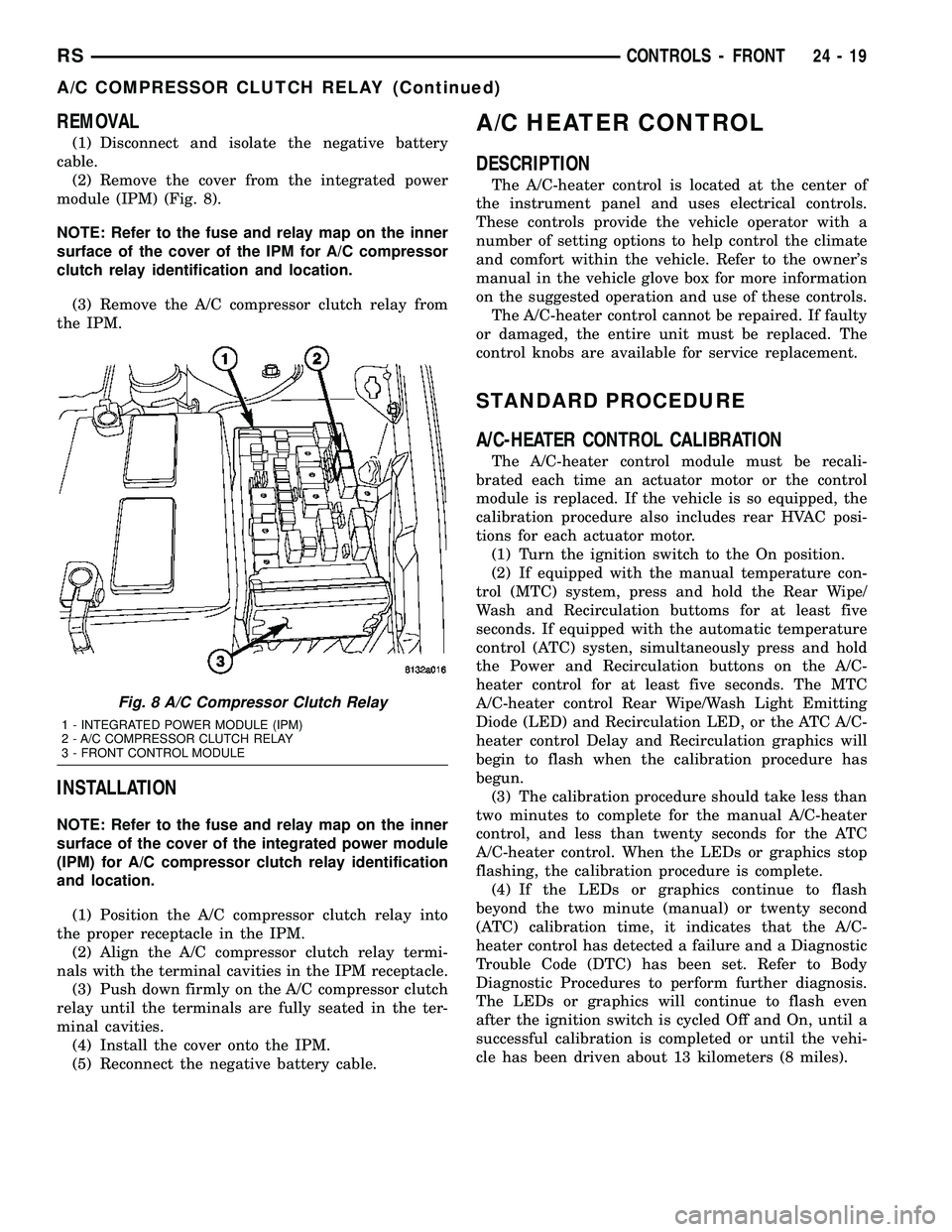
cable.
(2) Remove the cover from the integrated power
module (IPM) (Fig. 8).
NOTE: Refer to the fuse and relay map on the inner
surface of the cover of the IPM for A/C compressor
clutch relay identification and location.
(3) Remove the A/C compressor clutch relay from
the IPM.
INSTALLATION
NOTE: Refer to the fuse and relay map on the inner
surface of the cover of the integrated power module
(IPM) for A/C compressor clutch relay identification
and location.
(1) Position the A/C compressor clutch relay into
the proper receptacle in the IPM.
(2) Align the A/C compressor clutch relay termi-
nals with the terminal cavities in the IPM receptacle.
(3) Push down firmly on the A/C compressor clutch
relay until the terminals are fully seated in the ter-
minal cavities.
(4) Install the cover onto the IPM.
(5) Reconnect the negative battery cable.
A/C HEATER CONTROL
DESCRIPTION
The A/C-heater control is located at the center of
the instrument panel and uses electrical controls.
These controls provide the vehicle operator with a
number of setting options to help control the climate
and comfort within the vehicle. Refer to the owner's
manual in the vehicle glove box for more information
on the suggested operation and use of these controls.
The A/C-heater control cannot be repaired. If faulty
or damaged, the entire unit must be replaced. The
control knobs are available for service replacement.
STANDARD PROCEDURE
A/C-HEATER CONTROL CALIBRATION
The A/C-heater control module must be recali-
brated each time an actuator motor or the control
module is replaced. If the vehicle is so equipped, the
calibration procedure also includes rear HVAC posi-
tions for each actuator motor.
(1) Turn the ignition switch to the On position.
(2) If equipped with the manual temperature con-
trol (MTC) system, press and hold the Rear Wipe/
Wash and Recirculation buttoms for at least five
seconds. If equipped with the automatic temperature
control (ATC) systen, simultaneously press and hold
the Power and Recirculation buttons on the A/C-
heater control for at least five seconds. The MTC
A/C-heater control Rear Wipe/Wash Light Emitting
Diode (LED) and Recirculation LED, or the ATC A/C-
heater control Delay and Recirculation graphics will
begin to flash when the calibration procedure has
begun.
(3) The calibration procedure should take less than
two minutes to complete for the manual A/C-heater
control, and less than twenty seconds for the ATC
A/C-heater control. When the LEDs or graphics stop
flashing, the calibration procedure is complete.
(4) If the LEDs or graphics continue to flash
beyond the two minute (manual) or twenty second
(ATC) calibration time, it indicates that the A/C-
heater control has detected a failure and a Diagnostic
Trouble Code (DTC) has been set. Refer to Body
Diagnostic Procedures to perform further diagnosis.
The LEDs or graphics will continue to flash even
after the ignition switch is cycled Off and On, until a
successful calibration is completed or until the vehi-
cle has been driven about 13 kilometers (8 miles).
Fig. 8 A/C Compressor Clutch Relay
1 - INTEGRATED POWER MODULE (IPM)
2 - A/C COMPRESSOR CLUTCH RELAY
3 - FRONT CONTROL MODULE
RSCONTROLS - FRONT24-19
A/C COMPRESSOR CLUTCH RELAY (Continued)
Page 2179 of 2339
(8) Run the HVAC Cool Down test to verify system
is operating properly (Refer to 24 - HEATING & AIR
CONDITIONING - DIAGNOSIS AND TESTING).
RS MODELS
(1) Install the evaporator temperature sensor into
the top of the HVAC housing.
(2) Connect the wire harness connector to the
evaporator temperature sensor.
(3) Install the instrument panel (Refer to 23 -
BODY/INSTRUMENT PANEL/INSTRUMENT
PANEL ASSEMBLY - INSTALLATION).
(4) Reconnect the negative battery cable.
INFRARED TEMPERATURE
SENSOR
DESCRIPTION
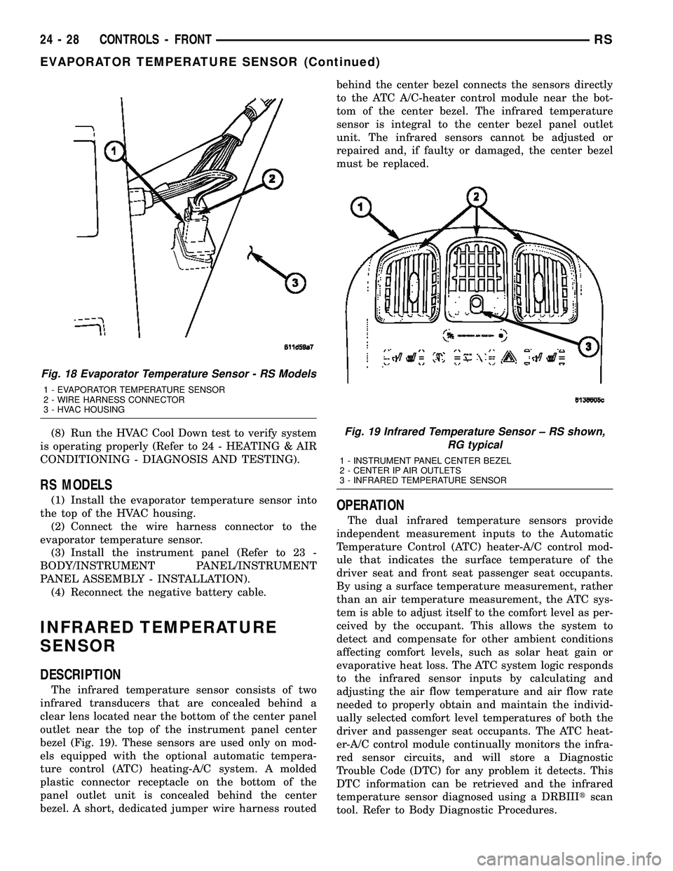
The infrared temperature sensor consists of two
infrared transducers that are concealed behind a
clear lens located near the bottom of the center panel
outlet near the top of the instrument panel center
bezel (Fig. 19). These sensors are used only on mod-
els equipped with the optional automatic tempera-
ture control (ATC) heating-A/C system. A molded
plastic connector receptacle on the bottom of the
panel outlet unit is concealed behind the center
bezel. A short, dedicated jumper wire harness routedbehind the center bezel connects the sensors directly
to the ATC A/C-heater control module near the bot-
tom of the center bezel. The infrared temperature
sensor is integral to the center bezel panel outlet
unit. The infrared sensors cannot be adjusted or
repaired and, if faulty or damaged, the center bezel
must be replaced.
OPERATION
The dual infrared temperature sensors provide
independent measurement inputs to the Automatic
Temperature Control (ATC) heater-A/C control mod-
ule that indicates the surface temperature of the
driver seat and front seat passenger seat occupants.
By using a surface temperature measurement, rather
than an air temperature measurement, the ATC sys-
tem is able to adjust itself to the comfort level as per-
ceived by the occupant. This allows the system to
detect and compensate for other ambient conditions
affecting comfort levels, such as solar heat gain or
evaporative heat loss. The ATC system logic responds
to the infrared sensor inputs by calculating and
adjusting the air flow temperature and air flow rate
needed to properly obtain and maintain the individ-
ually selected comfort level temperatures of both the
driver and passenger seat occupants. The ATC heat-
er-A/C control module continually monitors the infra-
red sensor circuits, and will store a Diagnostic
Trouble Code (DTC) for any problem it detects. This
DTC information can be retrieved and the infrared
temperature sensor diagnosed using a DRBIIItscan
tool. Refer to Body Diagnostic Procedures.
Fig. 18 Evaporator Temperature Sensor - RS Models
1 - EVAPORATOR TEMPERATURE SENSOR
2 - WIRE HARNESS CONNECTOR
3 - HVAC HOUSING
Fig. 19 Infrared Temperature Sensor ± RS shown,
RG typical
1 - INSTRUMENT PANEL CENTER BEZEL
2 - CENTER IP AIR OUTLETS
3 - INFRARED TEMPERATURE SENSOR
24 - 28 CONTROLS - FRONTRS
EVAPORATOR TEMPERATURE SENSOR (Continued)