2005 CHRYSLER VOYAGER remove seats
[x] Cancel search: remove seatsPage 1936 of 2339
INSTALLATION
(1) Place seat back frame into position.
(2) Install two bolts on each side of seat back
frame.
(3) Install strap at top of frame (Fig. 123).
(4) Install seat back cover and foam. (Refer to 23 -
BODY/SEATS/SEAT BACK COVER - INSTALLA-
TION).
SEAT BELT CENTER LAP BELT
- FOLD-IN-FLOOR
REMOVAL
(1) Set third row seat in the upright position.
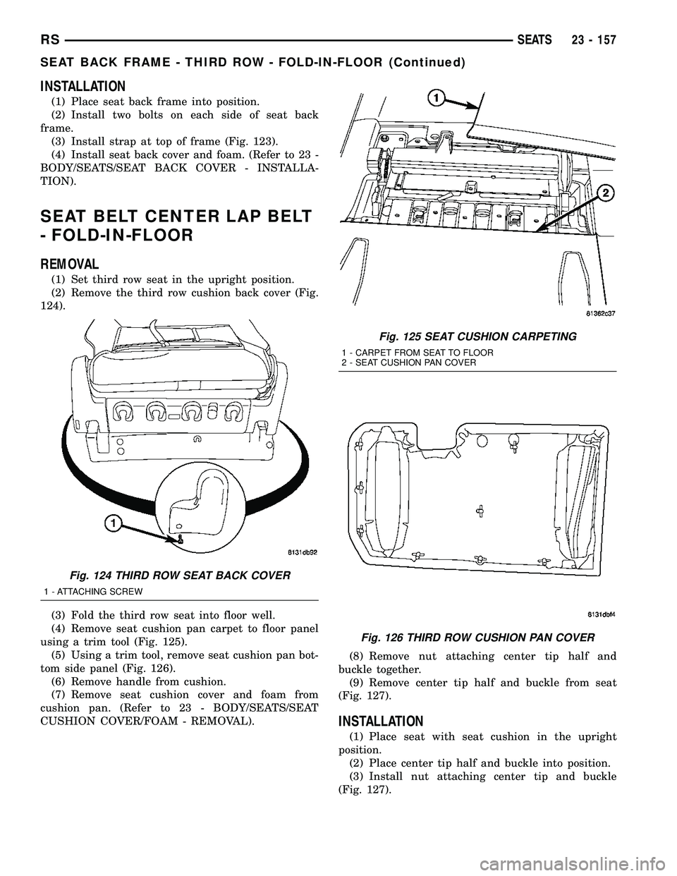
(2) Remove the third row cushion back cover (Fig.
124).
(3) Fold the third row seat into floor well.
(4) Remove seat cushion pan carpet to floor panel
using a trim tool (Fig. 125).
(5) Using a trim tool, remove seat cushion pan bot-
tom side panel (Fig. 126).
(6) Remove handle from cushion.
(7) Remove seat cushion cover and foam from
cushion pan. (Refer to 23 - BODY/SEATS/SEAT
CUSHION COVER/FOAM - REMOVAL).(8) Remove nut attaching center tip half and
buckle together.
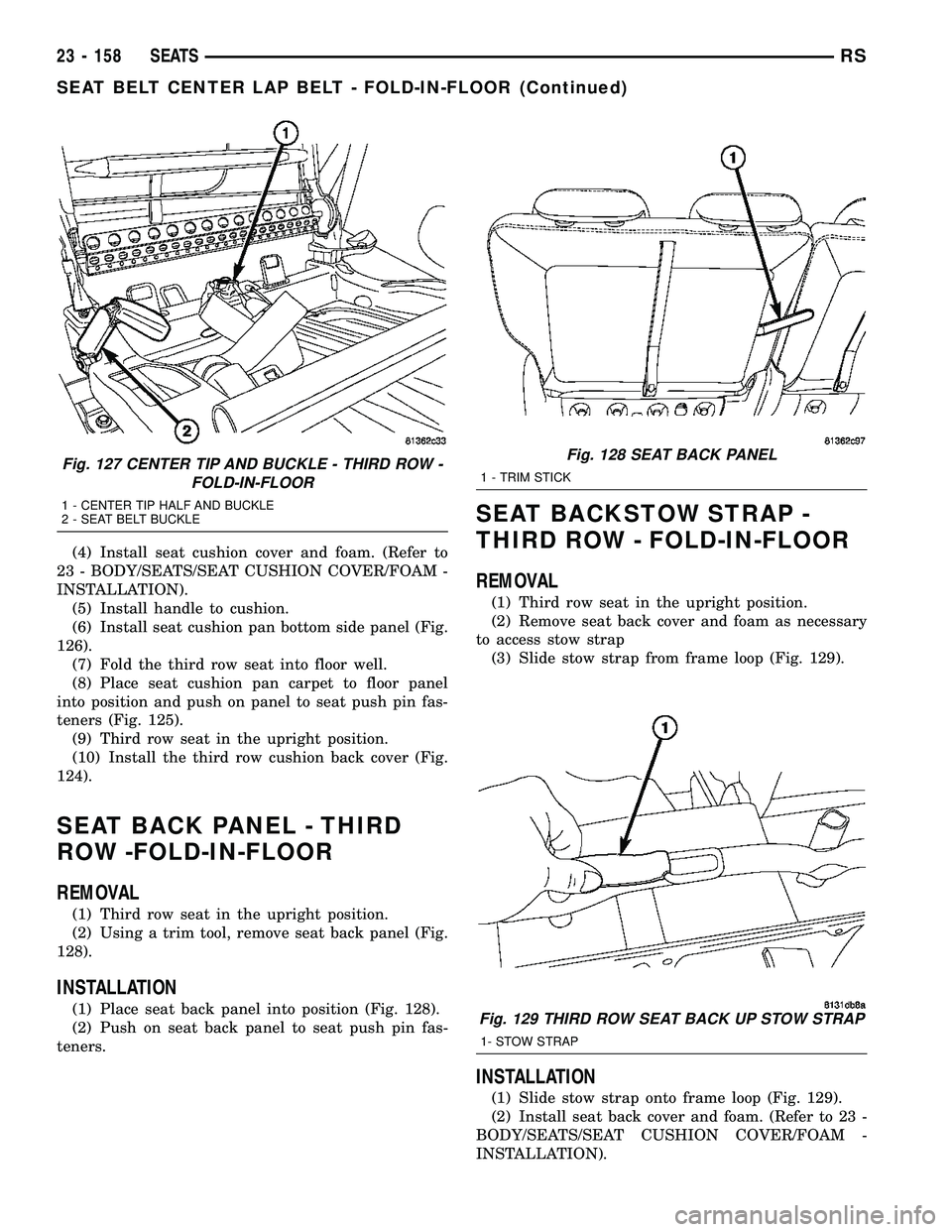
(9) Remove center tip half and buckle from seat
(Fig. 127).
INSTALLATION
(1) Place seat with seat cushion in the upright
position.
(2) Place center tip half and buckle into position.
(3) Install nut attaching center tip and buckle
(Fig. 127).
Fig. 124 THIRD ROW SEAT BACK COVER
1 - ATTACHING SCREW
Fig. 125 SEAT CUSHION CARPETING
1 - CARPET FROM SEAT TO FLOOR
2 - SEAT CUSHION PAN COVER
Fig. 126 THIRD ROW CUSHION PAN COVER
RSSEATS23 - 157
SEAT BACK FRAME - THIRD ROW - FOLD-IN-FLOOR (Continued)
Page 1937 of 2339
(4) Install seat cushion cover and foam. (Refer to
23 - BODY/SEATS/SEAT CUSHION COVER/FOAM -
INSTALLATION).
(5) Install handle to cushion.
(6) Install seat cushion pan bottom side panel (Fig.
126).
(7) Fold the third row seat into floor well.
(8) Place seat cushion pan carpet to floor panel
into position and push on panel to seat push pin fas-
teners (Fig. 125).
(9) Third row seat in the upright position.
(10) Install the third row cushion back cover (Fig.
124).
SEAT BACK PANEL - THIRD
ROW -FOLD-IN-FLOOR
REMOVAL
(1) Third row seat in the upright position.
(2) Using a trim tool, remove seat back panel (Fig.
128).
INSTALLATION
(1) Place seat back panel into position (Fig. 128).
(2) Push on seat back panel to seat push pin fas-
teners.
SEAT BACKSTOW STRAP -
THIRD ROW - FOLD-IN-FLOOR
REMOVAL
(1) Third row seat in the upright position.
(2) Remove seat back cover and foam as necessary
to access stow strap
(3) Slide stow strap from frame loop (Fig. 129).
INSTALLATION
(1) Slide stow strap onto frame loop (Fig. 129).
(2) Install seat back cover and foam. (Refer to 23 -
BODY/SEATS/SEAT CUSHION COVER/FOAM -
INSTALLATION).
Fig. 127 CENTER TIP AND BUCKLE - THIRD ROW -
FOLD-IN-FLOOR
1 - CENTER TIP HALF AND BUCKLE
2 - SEAT BELT BUCKLE
Fig. 128 SEAT BACK PANEL
1 - TRIM STICK
Fig. 129 THIRD ROW SEAT BACK UP STOW STRAP
1- STOW STRAP
23 - 158 SEATSRS
SEAT BELT CENTER LAP BELT - FOLD-IN-FLOOR (Continued)
Page 1938 of 2339
SEAT CUSHION COVER/FOAM -
THIRD ROW - FOLD-IN-FLOOR
REMOVAL
(1) Third row seat in the upright position.
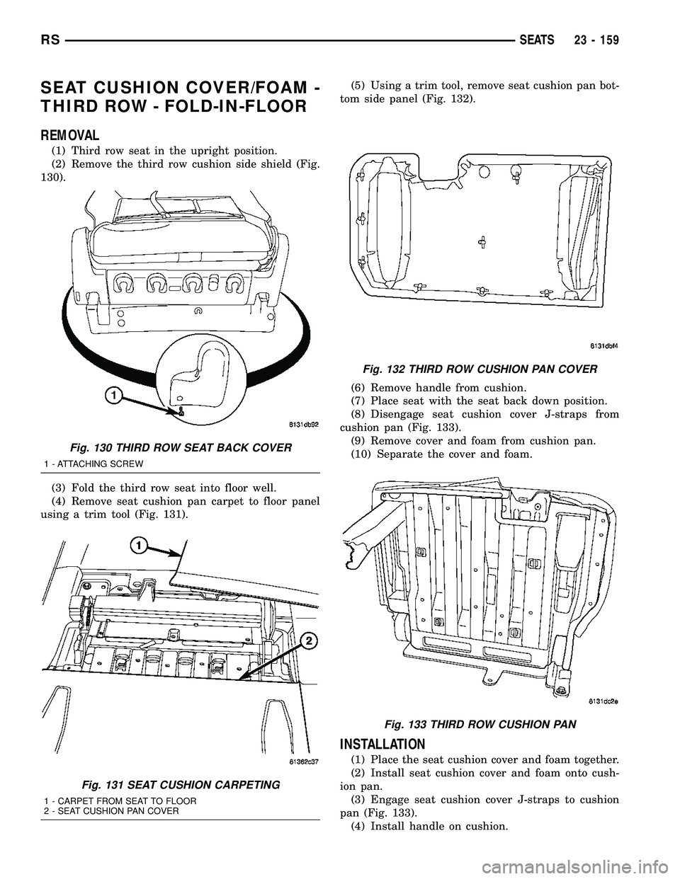
(2) Remove the third row cushion side shield (Fig.
130).
(3) Fold the third row seat into floor well.
(4) Remove seat cushion pan carpet to floor panel
using a trim tool (Fig. 131).(5) Using a trim tool, remove seat cushion pan bot-
tom side panel (Fig. 132).
(6) Remove handle from cushion.
(7) Place seat with the seat back down position.
(8) Disengage seat cushion cover J-straps from
cushion pan (Fig. 133).
(9) Remove cover and foam from cushion pan.
(10) Separate the cover and foam.
INSTALLATION
(1) Place the seat cushion cover and foam together.
(2) Install seat cushion cover and foam onto cush-
ion pan.
(3) Engage seat cushion cover J-straps to cushion
pan (Fig. 133).
(4) Install handle on cushion.
Fig. 130 THIRD ROW SEAT BACK COVER
1 - ATTACHING SCREW
Fig. 131 SEAT CUSHION CARPETING
1 - CARPET FROM SEAT TO FLOOR
2 - SEAT CUSHION PAN COVER
Fig. 132 THIRD ROW CUSHION PAN COVER
Fig. 133 THIRD ROW CUSHION PAN
RSSEATS23 - 159
Page 1939 of 2339
(5) Fold seat into floor well.
(6) Install seat cushion pan bottom side panel (Fig.
132).
(7) Install seat cushion pan carpet to floor panel
(Fig. 131).
(8) Install the third row cushion side shield (Fig.
130).
(9) Place third row seat in the upright position.
SIDE SHIELD CUP HOLDER -
FOLD-IN-FLOOR
REMOVAL
(1) Open cup holder door.
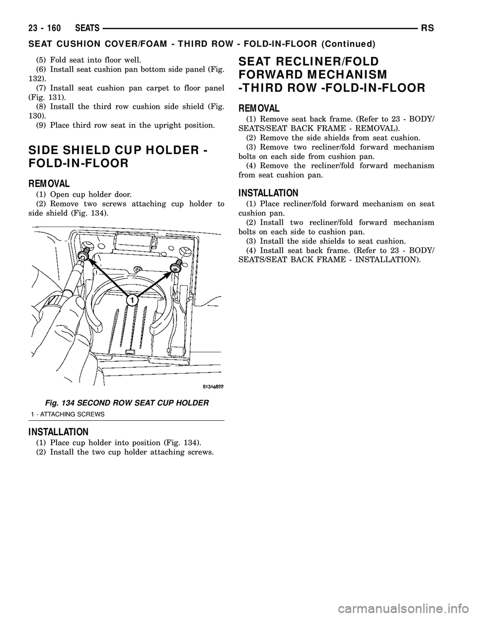
(2) Remove two screws attaching cup holder to
side shield (Fig. 134).
INSTALLATION
(1) Place cup holder into position (Fig. 134).
(2) Install the two cup holder attaching screws.
SEAT RECLINER/FOLD
FORWARD MECHANISM
-THIRD ROW -FOLD-IN-FLOOR
REMOVAL
(1) Remove seat back frame. (Refer to 23 - BODY/
SEATS/SEAT BACK FRAME - REMOVAL).
(2) Remove the side shields from seat cushion.
(3) Remove two recliner/fold forward mechanism
bolts on each side from cushion pan.
(4) Remove the recliner/fold forward mechanism
from seat cushion pan.
INSTALLATION
(1) Place recliner/fold forward mechanism on seat
cushion pan.
(2) Install two recliner/fold forward mechanism
bolts on each side to cushion pan.
(3) Install the side shields to seat cushion.
(4) Install seat back frame. (Refer to 23 - BODY/
SEATS/SEAT BACK FRAME - INSTALLATION).
Fig. 134 SECOND ROW SEAT CUP HOLDER
1 - ATTACHING SCREWS
23 - 160 SEATSRS
SEAT CUSHION COVER/FOAM - THIRD ROW - FOLD-IN-FLOOR (Continued)
Page 1951 of 2339
SYMPTOM POSSIBLE CAUSE
Sunshade will not function or does not
operate smoothlySunshade feet are missing, broken or loose.
No lubracation in track.
Track obstructions or interference.
Glass movement not consistant or glass does
not operate smoothlyGlass and Track timing.
Glass and Track alignment
Cables and Guide alignment
WATER DRAINAGE AND WIND NOISE DIAGNOSIS
The sliding glass panel is designed to seal water
entry with a snug fit between the roof and the seal.
The fit can be checked by inserting a piece of paper
between the roof and the seal. The piece of paper
should have some resistance when pulled out when
the glass panel is in the closed position. Excessive
wind noise could result if the gap clearances are
exceeded. The sunroof glass panel may need to be
adjusted. Refer to Sunroof Glass Panel Adjustment
for proper procedures.
Adequate drainage is provided by a drain trough in
the sunroof housing which encircles the sliding glass
panel and leads to drain hoses. If a wet headliner or
other water leak complaints are encountered, before
performing any adjustments, first ensure that the
drainage system is not plugged or disconnected. Use
a pint container to pour water into the sunroof hous-
ing drain trough. If water flow is restricted in any of
the four drain holes, use compressed air to blow out
any material plugging the drain system. Retest sys-
tem again.
To further check for a disconnected drain hose:
(1) Remove A-pillar trim, sun visors, and map
lamps/mini console.
(2) Remove sunroof opening trim lace. Refer to
Sunroof Opening Trim Lace.
NOTE: Care must be taken not to fold or kink the
headliner upon removal.
(3) Lower headliner as necessary to gain access to
sunroof housing drain tubes. Refer to Headlining
Removal and Installation for proper procedures.
(4) Repair as necessary.
DRAIN TUBE
REMOVAL
FRONT HOSES
NOTE: Front A-pillars are filled with sound deaden-
ing foam and the front drain tubes are sealed into
the pillars.
(1) Move glass panel to the fully closed position.
(2) Disconnect negative battery cable.
(3) Remove headliner (Refer to 23 - BODY/INTE-
RIOR/HEADLINER - REMOVAL).
(4) Disconnect the drain hose from the sunroof
housing (Fig. 1).
(5) Drain any liquid from hose connection, repair
as necessary.
REAR HOUSING HOSE
(1) Move glass panel to the fully closed position.
(2) Disconnect negative battery cable.
(3) Remove headliner (Refer to 23 - BODY/INTE-
RIOR/HEADLINER - REMOVAL).
(4) Remove third seat or seats from vehicle.
(5) Remove second seat belt lower anchor.
(6) Remove third seat lower anchor.
(7) Remove quarter trim bolster.
(8) Remove trim panel screws.
(9) Remove quarter trim panel
(10) Disconnect the drain hose from the sunroof
housing. (Fig. 1).
(11) Drain any liquid from hose connection, if nec-
essary, and remove tube.
INSTALLATION
FRONT HOSES
(1) Connect the new drain hose to the sunroof
housing and test drainage (Fig. 1).
(2) Install headliner (Refer to 23 - BODY/INTERI-
OR/HEADLINER - INSTALLATION).
(3) Install sunroof opening trim lace.
(4) Connect the control switch wire connector and
install control switch.
23 - 172 SUNROOFRS
SUNROOF (Continued)
Page 2207 of 2339
DISTRIBUTION - REAR
TABLE OF CONTENTS
page page
AIR OUTLETS
DESCRIPTION.........................56
REMOVAL.............................56
INSTALLATION.........................56
DISTRIBUTION DUCT
REMOVAL.............................57
INSTALLATION.........................57
BLOWER MOTOR
DESCRIPTION.........................57
OPERATION...........................57DIAGNOSIS AND TESTING
REAR BLOWER MOTOR................58
REMOVAL.............................58
INSTALLATION.........................60
HVAC HOUSING
REMOVAL.............................60
INSTALLATION.........................62
REAR FLOOR HEAT DUCT
REMOVAL.............................63
INSTALLATION.........................63
AIR OUTLETS
DESCRIPTION
Based upon the system mode selected, conditioned
air can exit the rear HVAC housing through one or a
combination of the two main housing outlets: air con-
ditioner, or heater. Once the conditioned air exits the
unit housing, it is directed through molded plastic
ducts to the various outlets in the vehicle interior.
These outlets and their locations are as follows:
²Floor Outlets- Three floor outlets with fixed
vanes are located in the right quarter trim panel,
near the floor. These outlets distribute air from the
rear floor heat duct to the intermediate and rear seat
occupants. The floor outlets are integral to the right
quarter trim panel and, if faulty or damaged, the
quarter trim panel must be replaced.
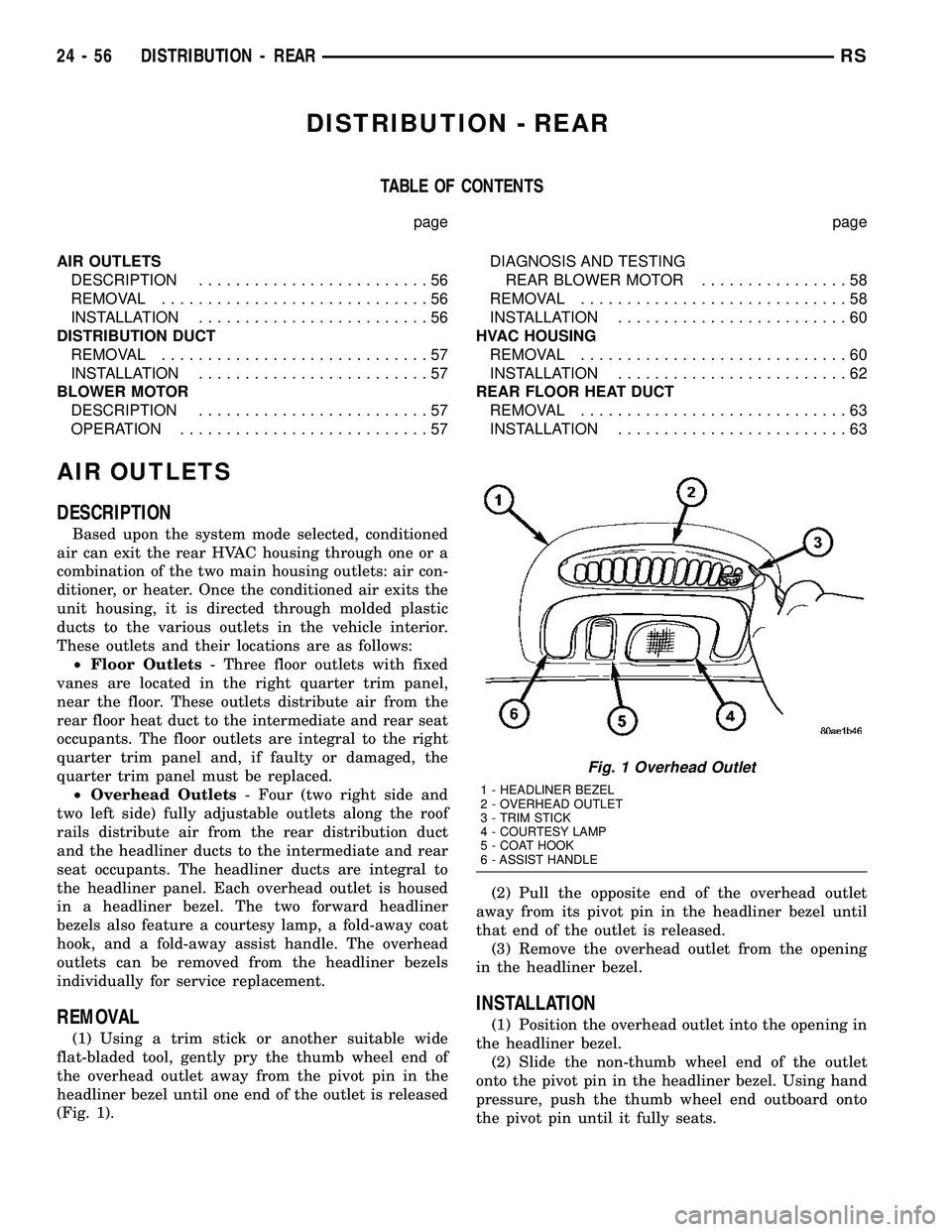
²Overhead Outlets- Four (two right side and
two left side) fully adjustable outlets along the roof
rails distribute air from the rear distribution duct
and the headliner ducts to the intermediate and rear
seat occupants. The headliner ducts are integral to
the headliner panel. Each overhead outlet is housed
in a headliner bezel. The two forward headliner
bezels also feature a courtesy lamp, a fold-away coat
hook, and a fold-away assist handle. The overhead
outlets can be removed from the headliner bezels
individually for service replacement.
REMOVAL
(1) Using a trim stick or another suitable wide
flat-bladed tool, gently pry the thumb wheel end of
the overhead outlet away from the pivot pin in the
headliner bezel until one end of the outlet is released
(Fig. 1).(2) Pull the opposite end of the overhead outlet
away from its pivot pin in the headliner bezel until
that end of the outlet is released.
(3) Remove the overhead outlet from the opening
in the headliner bezel.
INSTALLATION
(1) Position the overhead outlet into the opening in
the headliner bezel.
(2) Slide the non-thumb wheel end of the outlet
onto the pivot pin in the headliner bezel. Using hand
pressure, push the thumb wheel end outboard onto
the pivot pin until it fully seats.
Fig. 1 Overhead Outlet
1 - HEADLINER BEZEL
2 - OVERHEAD OUTLET
3 - TRIM STICK
4 - COURTESY LAMP
5 - COAT HOOK
6 - ASSIST HANDLE
24 - 56 DISTRIBUTION - REARRS
Page 2223 of 2339
(4) Open both the suction and discharge valves,
then open the charge valve to allow the heated
refrigerant to flow into the system.
(5) When the transfer of refrigerant has stopped,
close both the suction and discharge valves.
(6) If all of the refrigerant charge did not transfer
from the dispensing device, open all of the windows
in the vehicle and set the heater-air conditioner con-
trols so that the compressor is engaged and the
blower motor is operating at its lowest speed setting.
Run the engine at a steady high idle (about 1400
rpm). If the compressor will not engage, test the com-
pressor clutch control circuit and repair as required.
(7) Open the suction valve to allow the remaining
refrigerant to transfer to the refrigerant system.
WARNING: TAKE CARE NOT TO OPEN THE DIS-
CHARGE (HIGH PRESSURE) VALVE AT THIS TIME.
(8) Close the suction valve and test the system
performance. (Refer to 24 - HEATING & AIR CON-
DITIONING - STANDARD PROCEDURE - A/C PER-
FORMANCE TEST).
(9) Disconnect the charging station and manifold
gauge set from the refrigerant system service ports.
(10) Reinstall the caps onto the refrigerant system
service ports.
(11) Run the HVAC Control Cooldown test to ver-
ify proper operation(Refer to 24 - HEATING & AIR
CONDITIONING - DIAGNOSIS AND TESTING).
A/C COMPRESSOR
DESCRIPTION
A/C COMPRESSOR
Vehicles equipped with the 2.4L gasoline, 2.5L die-
sel, 2.8L diesel and 3.3L gasoline engines with the
front heating-A/C system only, use the Denso 10S17
A/C compressor. Vehicles equipped with the 3.3L and
the 3.8L gasoline engines with the optional rear heat-
ing-A/C system use the Denso 10S20 A/C compressor.
Both A/C compressors include an integral high pres-
sure relief valve. The A/C compressor is secured to a
mounting bracket on the 2.4L gasoline engine and
directly to the cylinder block on the 2.5L diesel, 2.8L
diesel, 3.3L gasoline and 3.8L gasoline engines.
HIGH PRESSURE RELIEF VALVE
A high pressure relief valve is located on the rear
of the A/C compressor. This mechanical valve is
designed to vent refrigerant from the A/C system to
protect against damage to the compressor and other
system components, caused by condenser air flow
restriction or an overcharge of refrigerant.
OPERATION
A/C COMPRESSOR
The A/C compressor is driven by the engine
through an electric clutch, drive pulley and belt
arrangement. The compressor is lubricated by refrig-
erant oil that is circulated throughout the refrigerant
system with the refrigerant.
The compressor draws in low-pressure refrigerant
vapor from the evaporator through its suction port. It
then compresses the refrigerant into a high-pressure,
high-temperature refrigerant vapor. The compressor
pumps the high-pressure refrigerant vapor to the
condenser through the compressor discharge port.
The compressor cannot be repaired. If faulty or
damaged, the entire compressor assembly must be
replaced. The compressor clutch, pulley and clutch
coil are available for service.
HIGH PRESSURE RELIEF VALVE
The high pressure relief valve vents the system
when a discharge pressure of 3445 to 4135 kPa (500
to 600 psi) or above is reached. The valve closes
when a minimum discharge pressure of 2756 kPa
(400 psi) is reached.
The high pressure relief valve vents only enough
refrigerant to reduce the system pressure, and then
re-seats itself. The majority of the refrigerant is con-
served in the system. If the valve vents refrigerant, it
does not mean that the valve is faulty.
The high pressure relief valve is a factory-cali-
brated unit. The valve cannot be adjusted or
repaired, and must not be removed or otherwise dis-
turbed. The valve is only serviced as a part of the
compressor assembly.
DIAGNOSIS AND TESTING
A/C COMPRESSOR NOISE DIAGNOSIS
Excessive noise while the air conditioning compres-
sor is operating can be caused by loose compressor
mounts, a loose compressor clutch, or high operating
pressures in the refrigerant system. Verify compres-
sor drive belt condition, proper compressor mounting,
correct refrigerant charge level, and compressor head
pressure before compressor repair is performed.
With the close tolerances within the compressor, it
is possible to experience a temporary lockup. The
longer the compressor is inactive, the more likely the
condition is to occur. This condition is the result of
normal refrigerant migration within the refrigerant
system caused by ambient temperature changes. The
refrigerant migration may wash the refrigerant oil
out of the compressor.
24 - 72 PLUMBING - FRONTRS
PLUMBING - FRONT (Continued)