2005 CHRYSLER CARAVAN Glove box light
[x] Cancel search: Glove box lightPage 405 of 2339

LAMPS/LIGHTING - INTERIOR
TABLE OF CONTENTS
page page
LAMPS/LIGHTING - INTERIOR
SPECIFICATIONS
INTERIOR LAMPS.....................20
CENTER CONSOLE LAMP
REMOVAL.............................21
INSTALLATION.........................21
CENTER CONSOLE LAMP SWITCH
REMOVAL.............................21
INSTALLATION.........................21
CLUSTER ILLUMINATION LAMPS
REMOVAL.............................21
INSTALLATION.........................21
COURTESY LAMP
REMOVAL.............................21
INSTALLATION.........................21DOME/CARGO LAMP
REMOVAL.............................22
INSTALLATION.........................22
GLOVE BOX LAMP SWITCH
REMOVAL.............................22
INSTALLATION.........................22
LIFTGATE LAMP
REMOVAL.............................22
INSTALLATION.........................22
READING LAMP
REMOVAL.............................22
INSTALLATION.........................23
VANITY LAMP
REMOVAL.............................24
INSTALLATION.........................24
LAMPS/LIGHTING - INTERIOR
SPECIFICATIONS
INTERIOR LAMPS
BULB APPLICATION TABLE
LAMP BULB
ABS LED
AIRBAG LED
ALARM SET LED
BRAKE SYSTEM
WARNINGLED
CONSOLE 194
CRUISE INDICATOR VFD*
DOME/RAIL LAMPS 578
DOOR AJAR INDICATOR LED
DOOR COURTESY
LAMP578
FRONT DOOR
COURTESY567
GLOVE BOX 194
HIGH BEAM INDICATOR LED
CLUSTER
ILLUMINATIONPC74
LIFTGATE 578
LAMP BULB
LIFTGATE AJAR LED
LOW FUEL INDICATOR LED
LOW WASHER FLUID
INDICATORLED
MIL LED
OIL INDICATOR LED
OVERHEAD CONSOLE
READINGPC579
PRNDL INDICATOR
(BASE CLUSTER)LED
PRNDL INDICATOR VFD
READING 578
SEAT BELT INDICATOR LED
TEMPERATURE
INDICATORLED
TIRE PRESSURE
WARNINGLED
TRAC OFF INDICATOR VFD*
VISOR VANITY 6501966
VOLTAGE INDICATOR LED
* VFD = VACUUM FLUORESCENT DISPLAY
8L - 20 LAMPS/LIGHTING - INTERIORRS
Page 407 of 2339

DOME/CARGO LAMP
REMOVAL
(1) Disconnect and isolate the battery negative
cable.
(2) Using a flat bladed tool, pry off the lamp lens.
(3) Remove bulb from lamp.
INSTALLATION
(1) Install bulb to lamp.
(2) Press lens into place.
(3) Connect battery negative cable.
GLOVE BOX LAMP SWITCH
REMOVAL
(1) Disconnect and isolate the battery negative
cable.
(2) Open glove box door.
(3) Push switch through from behind (Fig. 2).
(4) Disconnect wire harness from switch.
(5) Pull bulb from switch.
INSTALLATION
(1) Push bulb into switch.
(2) Connect wire harness to switch.
(3) Push switch into instrument panel.
(4) Close glove box door.
(5) Reconnect the battery negative cable.
LIFTGATE LAMP
REMOVAL
(1) Disconnect and isolate the battery negative
cable.
(2) Using a flat bladed tool, pry lamp from trim
panel (Fig. 3).
(3) Disconnect wire harness connector from lamp.
(4) Pry off lens and remove bulb.
INSTALLATION
(1) Install bulb and snap lens into place.
(2) Reconnect wire harness connector to lamp.
(3) Position lamp onto trim panel and snap into
place.
(4) Reconnect battery negative cable.
READING LAMP
REMOVAL
The front reading lamps are incorporated into the
overhead console. If the reading lamps require
replacement, the overhead console must be replaced.
(Refer to 8 - ELECTRICAL/OVERHEAD CONSOLE -
REMOVAL). The rear reading lamps are incorporated
into the assist handle. If the rear reading lamps
require replacement, the assist handle must be
replaced. (Refer to 23 - BODY/INTERIOR/ASSIST
HANDLE - REMOVAL). The bulbs can be serviced
separately.
Fig. 2 GLOVE BOX LAMP/SWITCH
1 - GLOVE BOX BULB
2 - GLOVE BOX LAMP SWITCH
Fig. 3 LIFTGATE LAMP
1 - LIFTGATE LAMP
2 - WIRE HARNESS
8L - 22 LAMPS/LIGHTING - INTERIORRS
Page 518 of 2339

WARNING: Wait two minutes for the airbag system
reserve capacitor to discharge before beginning
any airbag system or component service. Failure to
do so may result in accidental airbag deployment,
personal injury or death.
(4) Clean powder residue from interior of vehicle
(Refer to 8 - ELECTRICAL/RESTRAINTS - STAN-
DARD PROCEDURE - SERVICE AFTER AN AIR-
BAG DEPLOYMENT).
(5) Remove instrument panel (Refer to 23 - BODY/
INSTRUMENT PANEL/INSTRUMENT PANEL
ASSEMBLY - REMOVAL).
(6) Remove all reusable components from the
upper instrument panel and transfer to the new
instrument panel.
UNDEPLOYED AIRBAG
(1) Open hood.
(2) Disconnect and isolate the battery negative
cable.
(3)
WARNING: Wait two minutes for the airbag system
reserve capacitor to discharge before beginning
any airbag system or component service. Failure to
do so may result in accidental airbag deployment,
personal injury or death.
(4) Remove center console bin between front seats.
(5) Remove left front door sill plate using a trim
stick (special tool #C-4755) or equivalent, and gently
prying up on sill plate.
(6) Remove left cowl panel using a trim stick or
equivalent, and gently prying out on cowl panel.
(7) Remove four screws to lower steering column
cover and remove cover.
(8) Unsnap parking brake lever from knee blocker
reinforcement.
(9) Remove Data Link Connector (DLC) from knee
blocker.
(10) Remove screws to knee blocker.
(11) Unsnap left A-pillar lower extension trim
using a trim stick or equivalent.
(12) Remove three left side instrument panel A-pil-
lar retaining bolts and loosen the instrument panel
roll down bolt.
(13) Remove four nuts at brake pedal support
bracket to instrument panel.
(14) Using a trim stick or equivalent, gently pry
off left side upper A-pillar trim.
(15) Remove six screws and two wiring connectors
to lower instrument panel cubby bin at bottom of
center stack.
(16) Remove two left side nuts at instrument panel
center stack support to floor.(17) Remove two right side nuts at instrument
panel center stack support to floor.
(18) Remove right front door sill plate using a trim
stick or equivalent, and gently prying up on sill
plate.
(19) Remove right cowl panel using a trim stick or
equivalent, and gently prying out on cowl panel.
(20) Using a trim stick or equivalent, gently pry
out on right instrument panel end cap.
(21) Unsnap right A-pillar lower extension trim
using a trim stick or equivalent.
(22) Remove three right side instrument panel
A-pillar retaining bolts and loosen the instrument
panel roll down bolt.
(23) Using a trim stick or equivalent, gently pry
off right side upper A-pillar trim.
(24) Open glove box, pinch in sides and roll down
towards floor. With a firm pull, snap glove box door
off hinges and remove.
(25) Using a trim stick or equivalent, gently pry
up on rear of instrument panel top cover and then
pull rearward and out.
(26) Using a trim stick or equivalent, gently pry
off the filler bezel just above the cup holder to expose
the lower screws to center bezel.
(27) Remove two screws and then using a trim
stick or equivalent, gently pry off instrument panel
center bezel.
(28) Remove center bezel wiring connectors to
HVAC control and switch assembly (hazard, rear
wiper/washer, heated seats) and remove bezel.
(29) Slide cup holder assembly from instrument
panel.
(30) Remove nineteen screws to right lower instru-
ment panel trim (glove box surround), unplug glove
box lamp wire connector, and remove panel.
(31) Remove four screws and wiring connectors to
radio and remove radio.
(32) Remove one far left instrument panel speaker
retaining screw.
(33) Remove four screws along top front edge of
instrument panel cover/pad.
(34) Remove seven lower instrument panel cover/
pad retaining screws starting from right of vehicle
and only removing these seven, not all of them.
(35) Remove six upper fence line instrument panel
retaining bolts.
(36) Roll back instrument panel just enough to
increase access to the passenger airbag retaining
bolts at the reinforcement. Lift the instrument panel
up slightly so as not to damage the air distribution to
HVAC unit seal.
(37) Disconnect the passenger airbag electrical
connector. Using a trim stick or equivalent, gently
pry electrical connector off of instrument panel rein-
forcement.
RSRESTRAINTS8O-31
PASSENGER AIRBAG (Continued)
Page 519 of 2339

(38) Remove the two passenger airbag to instru-
ment panel cover/pad retaining screws.
(39) Remove the three passenger airbag to instru-
ment panel reinforcement retaining bolts.
(40) Pull rearward slightly on the instrument
panel cover/pad to maneuver passenger airbag out
from reinforcement and instrument panel.
INSTALLATION
DEPLOYED AIRBAG
Transfer all reusable components to the new
instrument panel.
(1) Install new Passenger Airbag into instrument
panel.
(2) Install airbag attaching bolts to the instrument
panel.
(a) Torque the two bolts at instrument panel
retainer bosses to 2.7 .5 N´m (24 5 in. lbs.).
(b) Torque the three bolts that attach the pas-
senger airbag to cross-car beam to 10 2 N´m (90
15 in. lbs.).
(3) Connect yellow wire connector to passenger air-
bag and affix connector to instrument panel rein-
forcement with push pins.
(4) Install Instrument panel (Refer to 23 - BODY/
INSTRUMENT PANEL/INSTRUMENT PANEL
ASSEMBLY - INSTALLATION).
WARNING: Do not connect the battery negative
cable (Refer to 8 - ELECTRICAL/RESTRAINTS -
DIAGNOSIS AND TESTING - AIRBAG SYSTEM). Per-
sonal injury or death may result if the system test
is not performed first.
UNDEPLOYED AIRBAG
(1) Pull rearward slightly on the instrument panel
cover/pad to maneuver passenger airbag up onto
reinforcement and instrument panel.
(2) Install the three passenger airbag to instru-
ment panel reinforcement retaining bolts but leave
loose. This will help align the passenger airbag for
the cover/pad fit.
(3) Install the two passenger airbag to instrument
panel cover/pad retaining screws. Torque screws to
2.7 .5 N´m (24 5 in. lbs.).
NOTE: Insure that the instrument panel cover/pad
locator pins are indexed properly at center stack
area prior to reassembly.
(4) Tighten the three passenger airbag to instru-
ment panel reinforcement retaining bolts. Torque
bolts to 10 2 N´m (90 15 in. lbs.).(5) Connect the passenger airbag electrical connec-
tor. Install the connector onto the instrument panel
reinforcement with the push-pin fasteners.
(6) Roll the instrument panel forward lifting
slightly so as to seat the instrument panel air distri-
bution duct on top of the HVAC unit properly to
avoid any leaks or damage to the seal.
(7) Install six upper fence line instrument panel
retaining bolts.
(8) Install three right side instrument panel A-pil-
lar retaining bolts and tighten the right instrument
panel roll down bolt. Install the smaller 10 mm bolt
first to align the instrument panel properly.
(9) Install three left side instrument panel A-pillar
retaining bolts and tighten the left instrument panel
roll down bolt. Install the smaller 10 mm bolt first to
align the instrument panel properly.
(10) Install seven lower instrument panel cover/
pad retaining screws.
(11) Install four screws along top front edge of
instrument panel cover/pad.
(12) Install one far left instrument panel speaker
retaining screw.
(13) Install wiring connectors to radio. Install
radio and four retaining screws.
(14) Connect glove box lamp wiring connector and
place right lower instrument panel trim (glove box
surround) into position.
(15) Install nineteen right lower instrument panel
trim (glove box surround) and install panel screws.
(16) Slide cup holder assembly into instrument
panel.
(17) Install center bezel wiring connectors to
HVAC control and switch assembly (hazard, rear
wiper/washer, heated seats).
(18) Install instrument panel center bezel by align-
ing slots and firmly snapping into place.
(19) Install two screws to instrument panel center
bezel.
(20) Align filler bezel above cup holder over retain-
ing slots and firmly snap into place.
(21) Place instrument panel top cover into position
and firmly snap down rear edge of top cover.
(22) Install glove box. Align hinges, snap into
place, roll glove box upwards and push in sides to
fully install.
(23) Align right side upper A-pillar trim over
retaining slots and firmly snap into place.
(24) Align right A-pillar lower extension trim over
retaining slots and firmly snap into place.
(25) Align right instrument panel end cap over
retaining slots and firmly snap into place.
(26) Align right cowl panel over retaining slots and
firmly snap into place.
(27) Align right front door sill plate over retaining
slots and firmly snap into place.
8O - 32 RESTRAINTSRS
PASSENGER AIRBAG (Continued)
Page 1856 of 2339
INSTRUMENT PANEL TOP PAD
ASSEMBLY
REMOVAL
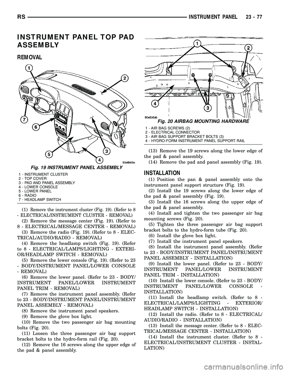
(1)Remove the instrument cluster (Fig. 19). (Refer to 8
- ELECTRICAL/INSTRUMENT CLUSTER - REMOVAL)
(2) Remove the message center (Fig. 19). (Refer to
8 - ELECTRICAL/MESSAGE CENTER - REMOVAL)
(3) Remove the radio (Fig. 19). (Refer to 8 - ELEC-
TRICAL/AUDIO/RADIO - REMOVAL)
(4) Remove the headlamp switch (Fig. 19). (Refer
to 8 - ELECTRICAL/LAMPS/LIGHTING - EXTERI-
OR/HEADLAMP SWITCH - REMOVAL)
(5) Remove the lower console (Fig. 19). (Refer to 23
- BODY/INSTRUMENT PANEL/LOWER CONSOLE
- REMOVAL)
(6) Remove the lower panel. (Refer to 23 - BODY/
INSTRUMENT PANEL/LOWER INSTRUMENT
PANEL TRIM - REMOVAL)
(7) Remove the instrument panel assembly. (Refer
to 23 - BODY/INSTRUMENT PANEL/INSTRUMENT
PANEL ASSEMBLY - REMOVAL)
(8) Remove the instrument panel speakers.
(9) Remove the glove box light.
(10) Remove the two passenger air bag mounting
bolts (Fig. 20).
(11) Loosen the three passenger air bag support
bracket bolts to the hydro-form rail (Fig. 20).
(12) Remove the 16 screws along the upper edge of
the pad & panel assembly.(13) Remove the 19 screws along the lower edge of
the pad & panel assembly.
(14) Remove the pad and panel assembly (Fig. 19).
INSTALLATION
(1) Position the pan & panel assembly onto the
instrument panel support structure (Fig. 19).
(2) Install the 19 screws along the lower edge of
the pad & panel assembly (Fig. 19).
(3) Install the 16 screws along the upper edge of
the pad & panel assembly.
(4) Install and tighten the two passenger air bag
mounting screws (Fig. 20).
(5) Tighten the three passenger air bag support
bracket bolts to the hydro-form tube (Fig. 20).
(6) Install the glove box light.
(7) Install the instrument panel speakers.
(8) Install the instrument panel assembly. (Refer
to 23 - BODY/INSTRUMENT PANEL/INSTRUMENT
PANEL ASSEMBLY - INSTALLATION)
(9) Install the lower panel. (Refer to 23 - BODY/
INSTRUMENT PANEL/LOWER INSTRUMENT
PANEL TRIM - INSTALLATION)
(10) Install the lower console. (Refer to 23 - BODY/
INSTRUMENT PANEL/LOWER CONSOLE -
INSTALLATION)
(11) Install the headlamp switch. (Refer to 8 -
ELECTRICAL/LAMPS/LIGHTING - EXTERIOR/
HEADLAMP SWITCH - INSTALLATION)
(12) Install the radio. (Refer to 8 - ELECTRICAL/
AUDIO/RADIO - INSTALLATION)
(13)
Install the message center. (Refer to 8 - ELEC-
TRICAL/MESSAGE CENTER - INSTALLATION)
(14) Install the instrument cluster. (Refer to 8 -
ELECTRICAL/INSTRUMENT CLUSTER - INSTAL-
LATION)
Fig. 19 INSTRUMENT PANEL ASSEMBLY
1 - INSTRUMENT CLUSTER
2 - TOP COVER
3 - PAD AND PANEL ASSEMBLY
4 - LOWER CONSOLE
5 - LOWER PANEL
6 - RADIO
7 - HEADLAMP SWITCH
Fig. 20 AIRBAG MOUNTING HARDWARE
1 - AIR BAG SCREWS (2)
2 - ELECTRICAL CONNECTOR
3 - AIR BAG SUPPORT BRACKET BOLTS (3)
4 - HYDRO-FORM INSTRUMENT PANEL SUPPORT RAIL
RSINSTRUMENT PANEL23-77
Page 2170 of 2339
REMOVAL
(1) Disconnect and isolate the negative battery
cable.
(2) Remove the cover from the integrated power
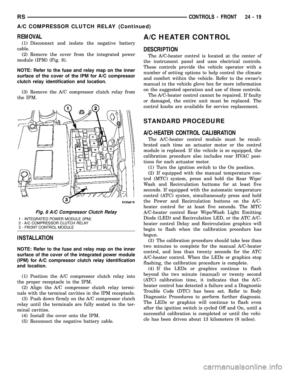
module (IPM) (Fig. 8).
NOTE: Refer to the fuse and relay map on the inner
surface of the cover of the IPM for A/C compressor
clutch relay identification and location.
(3) Remove the A/C compressor clutch relay from
the IPM.
INSTALLATION
NOTE: Refer to the fuse and relay map on the inner
surface of the cover of the integrated power module
(IPM) for A/C compressor clutch relay identification
and location.
(1) Position the A/C compressor clutch relay into
the proper receptacle in the IPM.
(2) Align the A/C compressor clutch relay termi-
nals with the terminal cavities in the IPM receptacle.
(3) Push down firmly on the A/C compressor clutch
relay until the terminals are fully seated in the ter-
minal cavities.
(4) Install the cover onto the IPM.
(5) Reconnect the negative battery cable.
A/C HEATER CONTROL
DESCRIPTION
The A/C-heater control is located at the center of
the instrument panel and uses electrical controls.
These controls provide the vehicle operator with a
number of setting options to help control the climate
and comfort within the vehicle. Refer to the owner's
manual in the vehicle glove box for more information
on the suggested operation and use of these controls.
The A/C-heater control cannot be repaired. If faulty
or damaged, the entire unit must be replaced. The
control knobs are available for service replacement.
STANDARD PROCEDURE
A/C-HEATER CONTROL CALIBRATION
The A/C-heater control module must be recali-
brated each time an actuator motor or the control
module is replaced. If the vehicle is so equipped, the
calibration procedure also includes rear HVAC posi-
tions for each actuator motor.
(1) Turn the ignition switch to the On position.
(2) If equipped with the manual temperature con-
trol (MTC) system, press and hold the Rear Wipe/
Wash and Recirculation buttoms for at least five
seconds. If equipped with the automatic temperature
control (ATC) systen, simultaneously press and hold
the Power and Recirculation buttons on the A/C-
heater control for at least five seconds. The MTC
A/C-heater control Rear Wipe/Wash Light Emitting
Diode (LED) and Recirculation LED, or the ATC A/C-
heater control Delay and Recirculation graphics will
begin to flash when the calibration procedure has
begun.
(3) The calibration procedure should take less than
two minutes to complete for the manual A/C-heater
control, and less than twenty seconds for the ATC
A/C-heater control. When the LEDs or graphics stop
flashing, the calibration procedure is complete.
(4) If the LEDs or graphics continue to flash
beyond the two minute (manual) or twenty second
(ATC) calibration time, it indicates that the A/C-
heater control has detected a failure and a Diagnostic
Trouble Code (DTC) has been set. Refer to Body
Diagnostic Procedures to perform further diagnosis.
The LEDs or graphics will continue to flash even
after the ignition switch is cycled Off and On, until a
successful calibration is completed or until the vehi-
cle has been driven about 13 kilometers (8 miles).
Fig. 8 A/C Compressor Clutch Relay
1 - INTEGRATED POWER MODULE (IPM)
2 - A/C COMPRESSOR CLUTCH RELAY
3 - FRONT CONTROL MODULE
RSCONTROLS - FRONT24-19
A/C COMPRESSOR CLUTCH RELAY (Continued)
Page 2181 of 2339
INSTALLATION
(1) Position the mode door actuator onto the HVAC
distribution housing. If necessary, rotate the actuator
slightly to align the splines on the actuator output
shaft with those in the mode door linkage.
(2) Install the two screws that secure the mode
door actuator to the distribution housing. Tighten the
screws to 2 N´m (17 in. lbs.).
(3) Connect the wire harness connector to the
mode door actuator.
(4) Install the silencer under the driver side end of
the instrument panel (Refer to 23 - BODY/INSTRU-
MENT PANEL/INSTRUMENT PANEL SILENCER -
INSTALLATION).
(5) Reconnect the negative battery cable.
(6) Perform the A/C-heater control calibration pro-
cedure (Refer to 24 - HEATING & AIR CONDITION-
ING/CONTROLS - FRONT/A/C-HEATER CONTROL
- STANDARD PROCEDURE - HEATER-A/C CON-
TROL CALIBRATION).
POWER MODULE - BLOWER
MOTOR
DESCRIPTION
A blower motor power module is used on this
model when it is equipped with the optional Auto-
matic Temperature Control (ATC) system. Models
equipped with the standard manual heater-A/C sys-
tem use a blower motor resistor block, instead of the
blower motor power module (Refer to 24 - HEATING
& AIR CONDITIONING/CONTROLS/BLOWER
MOTOR RESISTOR BLOCK - DESCRIPTION).
The blower motor power module is mounted to the
rear of the HVAC housing, directly behind the glove
box opening in the instrument panel. The module
consists of a molded plastic mounting plate with two
integral connector receptacles. Concealed behind the
mounting plate is the power module electronic cir-
cuitry and a large finned, heat sink. The blower
motor power module is accessed for service by remov-
ing the glove box from the instrument panel.
OPERATION
The blower motor power module is connected to the
vehicle electrical system through a dedicated lead
and connector from the instrument panel wire har-
ness. A second connector receptacle receives a wire
lead connector from the blower motor. The blower
motor power module allows the microprocessor-based
Automatic Temperature Control (ATC) heater-A/C
control module to calculate and provide infinitely
variable blower motor speeds based upon either man-
ual blower switch input or the ATC programming
using a Pulse Width Modulated (PWM) circuit strat-
egy. The PWM voltage is applied to a comparator cir-
cuit which compares the PWM signal voltage to the
blower motor feedback voltage. The resulting output
drives the power module circuitry, which adjusts the
voltage output received from the blower motor relay
to change or maintain the desired blower speed. The
blower motor power module is diagnosed using a
DRBIIItscan tool. Refer to Body Diagnostic Proce-
dures.
REMOVAL
WARNING: ON VEHICLES EQUIPPED WITH AIR-
BAGS, DISABLE THE AIRBAG SYSTEM BEFORE
ATTEMPTING ANY STEERING WHEEL, STEERING
COLUMN, OR INSTRUMENT PANEL COMPONENT
DIAGNOSIS OR SERVICE. DISCONNECT AND ISO-
LATE THE BATTERY NEGATIVE (GROUND) CABLE,
THEN WAIT TWO MINUTES FOR THE AIRBAG SYS-
TEM CAPACITOR TO DISCHARGE BEFORE PER-
FORMING FURTHER DIAGNOSIS OR SERVICE. THIS
IS THE ONLY SURE WAY TO DISABLE THE AIRBAG
SYSTEM. FAILURE TO TAKE THE PROPER PRE-
CAUTIONS COULD RESULT IN ACCIDENTAL AIR-
BAG DEPLOYMENT AND POSSIBLE PERSONAL
INJURY.
WARNING: THE HEAT SINK FOR THE BLOWER
MOTOR POWER MODULE MAY GET VERY HOT
DURING NORMAL OPERATION. IF THE BLOWER
MOTOR WAS TURNED ON PRIOR TO SERVICING
THE BLOWER MOTOR POWER MODULE, WAIT
FIVE MINUTES TO ALLOW THE HEAT SINK TO
COOL BEFORE PERFORMING DIAGNOSIS OR SER-
VICE. FAILURE TO TAKE THIS PRECAUTION CAN
RESULT IN PERSONAL INJURY.
24 - 30 CONTROLS - FRONTRS
MODE DOOR ACTUATOR (Continued)
Page 2319 of 2339
INTERMEDIATE - INSTALLATION, CABLE- PARKING BRAKE ..................... 5-69
INTERMEDIATE - REMOVAL, CABLE - PARKING BRAKE ...................... 5-69
INTERNATIONAL SYMBOLS - DESCRIPTION .........................0-1
INTRODUCTION - DIAGNOSIS AND TESTING, ENGINE DIAGNOSIS ........9-3,9-78
IOD FUSE - DESCRIPTION ...........8W-97-3
IOD FUSE - OPERATION .............8W-97-3
JOINT - DESCRIPTION, LOWER BALL ......2-10
JOINT - DIAGNOSIS AND TESTING, LOWER BALL ........................ 2-10
JOINT - OPERATION, LOWER BALL .......2-10
JOINT MOLDING - INSTALLATION, ROOF . . 23-60
JOINT MOLDING - REMOVAL, ROOF ......23-60
JOUNCE BUMPER - DESCRIPTION ........2-35
JOUNCE BUMPER - OPERATION ..........2-35
JUMP STARTING - STANDARD PROCEDURE ......................... 0-25
JUNCTION BLOCK - DESCRIPTION, NON-ABS ............................ 5-33
JUNCTION BLOCK - INSTALLATION, NON-ABS ............................ 5-34
JUNCTION BLOCK - OPERATION, NON-ABS ............................ 5-33
JUNCTION BLOCK - REMOVAL, NON-ABS . . 5-34
KEY - DESCRIPTION, TRANSPONDER .....8Q-6
KEY - OPERATION, TRANSPONDER .......8Q-6
KEY LOCK TUMBLER - FOLD-IN-FLOOR - INSTALLATION, FLOOR CONSOLE ........23-90
KEY LOCK TUMBLER - FOLD-IN-FLOOR - REMOVAL, FLOOR CONSOLE ...........23-90
KEY REMOTE ENTRY MODULE - DESCRIPTION, SENTRY ................8Q-3
KEY REMOTE ENTRY MODULE - DIAGNOSIS AND TESTING, SENTRY .......8Q-5
KEY REMOTE ENTRY MODULE - INSTALLATION, SENTRY ................8Q-6
KEY REMOTE ENTRY MODULE - OPERATION, SENTRY .................. 8Q-4
KEY REMOTE ENTRY MODULE - REMOVAL, SENTRY ................... 8Q-6
KEY REMOTE ENTRY SYSTEM - DIAGNOSIS AND TESTING, SENTRY .......8Q-3
KEYLESS ENTRY TRANSMITTER, DIAGNOSIS AND TESTING .............8N-24
KEYLESS ENTRY TRANSMITTER PROGRAMMING - STANDARD
PROCEDURE, REMOTE ................8N-24
KEY/LOCK CYLINDER - DESCRIPTION ....19-20
KEY/LOCK CYLINDER - INSTALLATION ....19-20
KEY/LOCK CYLINDER - OPERATION ......19-20
KEY/LOCK CYLINDER - REMOVAL .......19-20
KNEE - INSTALLATION, BLOCKER- INFLATABLE ......................... 23-75
KNEE - REMOVAL, BLOCKER- INFLATABLE ......................... 23-75
KNEE BLOCKER AIRBAG - DESCRIPTION . . 8O-22
KNEE BLOCKER AIRBAG - INSTALLATION . 8O-23
KNEE BLOCKER AIRBAG - OPERATION . . . 8O-22
KNEE BLOCKER AIRBAG - REMOVAL .....8O-23
KNOB - INSTALLATION, SEAT BELT HEIGHT ADJUSTER ................... 8O-38
KNOB - REMOVAL, SEAT BELT HEIGHT ADJUSTER ......................... 8O-38
KNOCK SENSOR - DESCRIPTION ..........8I-8
KNOCK SENSOR - OPERATION ...........8I-8
KNUCKLE - DESCRIPTION ................2-6
KNUCKLE - INSPECTION, STEERING ........2-9
KNUCKLE - INSTALLATION, STEERING ......2-9
KNUCKLE - OPERATION .................2-7
KNUCKLE - REMOVAL, STEERING .........2-7
LABEL, DESCRIPTION - VEHICLE EMISSION CONTROL INFORMATION .......25-1
LAMP - DESCRIPTION, VTSS/SKIS INDICATOR .......................... 8Q-8
LAMP - DIAGNOSIS AND TESTING, FRONT FOG .......................... 8L-7
LAMP - INSTALLATION, CENTER CONSOLE ........................... 8L-21
LAMP - INSTALLATION, CENTER HIGH MOUNTED STOP ...................... 8L-6
LAMP - INSTALLATION, COURTESY ......8L-21
LAMP - INSTALLATION, DOME/CARGO ....8L-22
LAMP - INSTALLATION, FRONT FOG .......8L-8
LAMP - INSTALLATION, LICENSE ........8L-17
LAMP - INSTALLATION, LIFTGATE .......8L-22 LAMP - INSTALLATION, PARK/TURN
SIGNAL ............................ 8L-18
LAMP - INSTALLATION, READING ........8L-23
LAMP - INSTALLATION, TAIL ...........8L-19
LAMP - INSTALLATION, VANITY .........8L-24
LAMP - OPERATION, VTSS/SKIS INDICATOR .......................... 8Q-8
LAMP - REMOVAL, CENTER CONSOLE ....8L-21
LAMP - REMOVAL, CENTER HIGH MOUNTED STOP ...................... 8L-6
LAMP - REMOVAL, COURTESY ..........8L-21
LAMP - REMOVAL, DOME/CARGO .......8L-22
LAMP - REMOVAL, FRONT FOG ..........8L-8
LAMP - REMOVAL, LICENSE ............8L-17
LAMP - REMOVAL, LIFTGATE ...........8L-22
LAMP - REMOVAL, PARK/TURN SIGNAL . . 8L-18
LAMP - REMOVAL, READING ...........8L-22
LAMP - REMOVAL, TAIL ...............8L-18
LAMP - REMOVAL, VANITY .............8L-24
LAMP SWITCH - DESCRIPTION, BRAKE ....8L-4
LAMP SWITCH - DIAGNOSIS AND TESTING, BRAKE ...................... 8L-4
LAMP SWITCH - INSTALLATION, BRAKE . . . 8L-5
LAMP SWITCH - INSTALLATION, CENTER CONSOLE ........................... 8L-21
LAMP SWITCH - INSTALLATION, GLOVE BOX ............................... 8L-22
LAMP SWITCH - OPERATION, BRAKE ......8L-4
LAMP SWITCH - REMOVAL, BRAKE .......8L-5
LAMP SWITCH - REMOVAL, CENTER CONSOLE ........................... 8L-21
LAMP SWITCH - REMOVAL, GLOVE BOX . . 8L-22
LAMP UNIT - INSTALLATION, CENTER HIGH MOUNTED STOP .................8L-6
LAMP UNIT - INSTALLATION, TAIL .......8L-19
LAMP UNIT - REMOVAL, CENTER HIGH MOUNTED STOP ...................... 8L-6
LAMP UNIT - REMOVAL, TAIL ...........8L-19
LAMP UNIT ALIGNMENT - EXPORT - STANDARD PROCEDURE, FRONT FOG .....8L-9
LAMP UNIT ALIGNMENT - STANDARD PROCEDURE, FRONT FOG ...............8L-9
LAMPS - INSTALLATION, CLUSTER ILLUMINATION ...................... 8L-21
LAMPS - REMOVAL, CLUSTER ILLUMINATION ...................... 8L-21
LAMPS, SPECIFICATIONS - EXTERIOR .....8L-3
LAMPS, SPECIFICATIONS - INTERIOR ....8L-20
LAMPS/LIGHTING - EXTERIOR - DESCRIPTION ........................ 8L-2
LAMPS/LIGHTING - EXTERIOR - OPERATION .......................... 8L-2
LAMPS/LIGHTING - EXTERIOR - WARNING ........................... 8L-3
LAP BELT - FOLD-IN-FLOOR - INSTALLATION, SEAT BELT CENTER .....23-157
LAP BELT - FOLD-IN-FLOOR - REMOVAL, SEAT BELT CENTER .................. 23-157
LASH ADJUSTER NOISE DIAGNOSIS - DIAGNOSIS AND TESTING, HYDRAULIC ....9-34
LASH ADJUSTERS - INSTALLATION, HYDRAULIC .......................... 9-35
LASH ADJUSTERS - REMOVAL, HYDRAULIC .......................... 9-35
LATCH - DESCRIPTION ...........8N-12,8N-49
LATCH - FOLD-IN-FLOOR - INSTALLATION, FLOOR CONSOLE LID ....23-90
LATCH - FOLD-IN-FLOOR - REMOVAL, FLOOR CONSOLE LID .................23-90
LATCH - INSTALLATION .....23-18,23-41,23-63
LATCH - INSTALLATION ..........8N-13,8N-50
LATCH - INSTALLATION, FUEL FILL DOOR BLOCKER ..................... 23-53
LATCH - INSTALLATION, GLOVE BOX .....23-66
LATCH - INSTALLATION, HOLD OPEN .....23-25
LATCH / LOCK ASSEMBLY - INSTALLATION ....................... 23-27
LATCH / LOCK ASSEMBLY - REMOVAL ....23-26
LATCH - OPERATION ............8N-12,8N-49
LATCH - REMOVAL .........23-18,23-41,23-63
LATCH - REMOVAL ..............8N-12,8N-49
LATCH - REMOVAL, FUEL FILL DOOR BLOCKER ........................... 23-53
LATCH - REMOVAL, GLOVE BOX .........23-66
LATCH - REMOVAL, HOLD OPEN ........23-25
LATCH ACTUATOR - DESCRIPTION ......8N-13
LATCH ACTUATOR - INSTALLATION ......8N-14
LATCH ACTUATOR - OPERATION ........8N-13 LATCH ACTUATOR - REMOVAL
..........8N-13
LATCH CABLE - INSTALLATION, HOLD OPEN .............................. 23-38
LATCH CABLE - REMOVAL, HOLD OPEN . . . 23-38
LATCH HANDLE - INSTALLATION, INSIDE . . 23-34
LATCH HANDLE - REMOVAL, INSIDE .....23-34
LATCH LOCKING LINK - INSTALLATION, SEAT RISER ........................ 23-151
LATCH LOCKING LINK - REMOVAL, SEAT RISER ............................ 23-151
LATCH RELEASE CABLE - INSTALLATION . . 23-64
LATCH RELEASE CABLE - REMOVAL .....23-63
LATCH STRIKER - INSTALLATION . . 23-19,23-42, 23-64
LATCH STRIKER - INSTALLATION, FUEL FILL DOOR BLOCKER .................23-53
LATCH STRIKER - INSTALLATION, GLOVE BOX ............................... 23-66
LATCH STRIKER - INSTALLATION, HOLD OPEN .............................. 23-26
LATCH STRIKER - INSTALLATION, REAR . . 23-29
LATCH STRIKER - REMOVAL . 23-19,23-41,23-64
LATCH STRIKER - REMOVAL, FUEL FILL DOOR BLOCKER ..................... 23-53
LATCH STRIKER - REMOVAL, GLOVE BOX ............................... 23-66
LATCH STRIKER - REMOVAL, HOLD OPEN .............................. 23-26
LATCH STRIKER - REMOVAL, REAR ......23-29
LEAD - DIAGNOSIS AND TESTING, TIRE/VEHICLE ......................... 22-14
LEAF SPRING FRONT - INSTALLATION, BUSHING ............................ 2-30
LEAF SPRING FRONT - REMOVAL, BUSHING ............................ 2-29
LEAK DETECTION ASSY - INSTALLATION, NATURAL VAC ....................... 25-14
LEAK DETECTION ASSY - REMOVAL, NATURAL VAC ....................... 25-14
LEAK DETECTION PUMP - INSTALLATION . 25-15
LEAK DETECTION PUMP - REMOVAL .....25-15
LEAK INSPECTION - DIAGNOSIS AND TESTING, ENGINE OIL ...............9-8,9-84
LEAK REPAIRING - STANDARD PROCEDURE, TIRE ................... 22-17
LEAK TEST - DIAGNOSIS AND TESTING, COOLING SYSTEM .....................7-2
LEAKAGE - DIAGNOSIS AND TESTING, TORQUE CONVERTER HOUSING FLUID . . 21-154, 21-9
LEAKAGE TEST - DIAGNOSIS AND TESTING, CYLINDER COMBUSTION
PRESSURE ....................... 9-85,9-9
LEAKS - DIAGNOSIS AND TESTING, INTAKE MANIFOLD ...............9-147,9-60
LEAKS, DIAGNOSIS AND TESTING - REFRIGERANT SYSTEM ...............24-67
LEAKS, DIAGNOSIS AND TESTING - WATER ............................. 23-1
LEARN CYCLE, STANDARD PROCEDURE - POWER LIFTGATE ................... 8N-8
LEARN CYCLE, STANDARD PROCEDURE - POWER SLIDING DOOR ..............8N-48
LEARN PROCEDURE - STANDARD PROCEDURE, QUICK .................. 8E-15
LENS - INSTALLATION, CLUSTER ........8J-11
LENS - REMOVAL, CLUSTER ............8J-11
LEVEL AND CONDITION CHECK, STANDARD PROCEDURE - FLUID . . 21-230,21-82
LEVEL CHECK - STANDARD PROCEDURE, COOLANT .................7-4
LEVEL CHECK - STANDARD PROCEDURE, ENGINE OIL ..............9-140
LEVEL CHECK, STANDARD PROCEDURE - ENGINE OIL ........................ 9-54
LEVEL CHECKING - STANDARD PROCEDURE, BRAKE FLUID .............5-33
LEVEL CHECKING - STANDARD PROCEDURE, POWER STEERING FLUID . . . 19-44
LEVEL SENDING UNIT / SENSOR - DESCRIPTION, FUEL ................... 14-5
LEVEL SENDING UNIT / SENSOR - INSTALLATION, FUEL .................. 14-6
LEVEL SENDING UNIT / SENSOR - OPERATION, FUEL ..................... 14-5
LEVEL SENDING UNIT / SENSOR - REMOVAL, FUEL ...................... 14-5
18 INDEXRS
Description Group-Page Description Group-Page Description Group-Page