2005 CHRYSLER CARAVAN radio
[x] Cancel search: radioPage 1115 of 2339
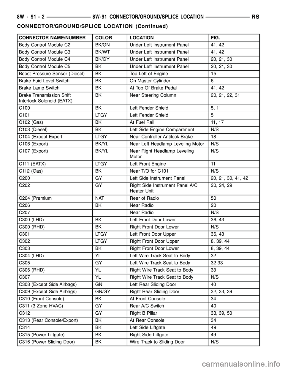
CONNECTOR NAME/NUMBER COLOR LOCATION FIG.
Body Control Module C2 BK/GN Under Left Instrument Panel 41, 42
Body Control Module C3 BK/WT Under Left Instrument Panel 41, 42
Body Control Module C4 BK/GY Under Left Instrument Panel 20, 21, 30
Body Control Module C5 BK Under Left Instrument Panel 20, 21, 30
Boost Pressure Sensor (Diesel) BK Top Left of Engine 15
Brake Fuid Level Switch BK On Master Cylinder 6
Brake Lamp Switch BK At Top Of Brake Pedal 41, 42
Brake Transmission Shift
Interlock Solenoid (EATX)BK Near Steering Column 20, 21, 22, 31
C100 BK Left Fender Shield 5, 11
C101 LTGY Left Fender Shield 5
C102 (Gas) BK At Fuel Rail 11, 17
C103 (Diesel) BK Left Side Engine Compartment N/S
C104 (Except Export LTGY Near Controller Antilock Brake 18
C106 (Export) BK/YL Near Left Headlamp Leveling Motor N/S
C107 (Export) BK/YL Near Right Headlamp Leveling
MotorN/S
C111 (EATX) LTGY Left Front Engine 11
C112 (Gas) BK Near T/O for C101 N/S
C200 GY Left Side Instrument Panel 20, 21, 30, 41, 42
C202 GY Right Side Instrument Panel A/C
Heater Unit20, 24, 29
C204 (Premium NAT Rear of Radio 50
C206 BK Near Radio 20
C207 Near Radio N/S
C300 (LHD) BK Left Front Door Lower 36, 43
C300 (RHD) BK Right Front Door Lower N/S
C301 LTGY Left Front Door Upper 36, 43
C302 LTGY Right Front Door Upper 8, 39, 44
C303 BK Right Front Door Lower 8, 39, 44
C304 (LHD) YL Left Wire Track Seat to Body 32
C305 GY Left Wire Track Seat to Body 32 33
C306 (RHD) YL Right Wire Track Seat to Body 33
C307 YL Right Wire Track Seat to Body N/S
C308 (Except Side Airbags) GN Left Rear Sliding Door 40
C309 (Except Side Airbags) GN/GY Right Rear Sliding Door 32, 33, 39
C310 (Front Console) BK At Front Console 34
C311 (3 Zone HVAC) GY Rear A/C Switch 40
C312 GY Right B Pillar 33, 39, 50
C313 (Rear Console/Export) BK At Rear Console 34
C314 BK Left Side Liftgate 49
C315 (Power Liftgate) BK Right Side Liftgate 49
C316 (Power Sliding Door) BK Wire Track to Sliding Door N/S
8W - 91 - 2 8W-91 CONNECTOR/GROUND/SPLICE LOCATIONRS
CONNECTOR/GROUND/SPLICE LOCATION (Continued)
Page 1117 of 2339
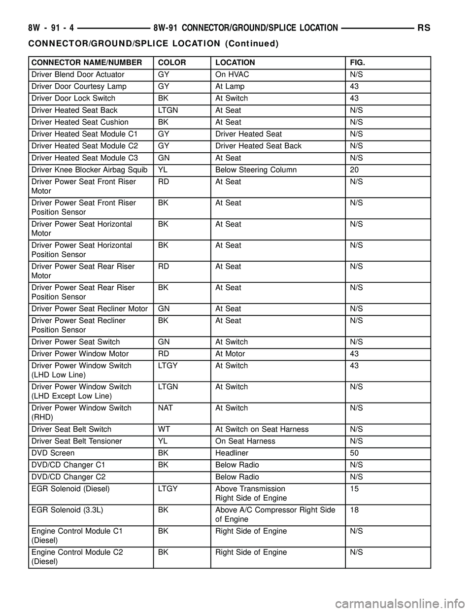
CONNECTOR NAME/NUMBER COLOR LOCATION FIG.
Driver Blend Door Actuator GY On HVAC N/S
Driver Door Courtesy Lamp GY At Lamp 43
Driver Door Lock Switch BK At Switch 43
Driver Heated Seat Back LTGN At Seat N/S
Driver Heated Seat Cushion BK At Seat N/S
Driver Heated Seat Module C1 GY Driver Heated Seat N/S
Driver Heated Seat Module C2 GY Driver Heated Seat Back N/S
Driver Heated Seat Module C3 GN At Seat N/S
Driver Knee Blocker Airbag Squib YL Below Steering Column 20
Driver Power Seat Front Riser
MotorRD At Seat N/S
Driver Power Seat Front Riser
Position SensorBK At Seat N/S
Driver Power Seat Horizontal
MotorBK At Seat N/S
Driver Power Seat Horizontal
Position SensorBK At Seat N/S
Driver Power Seat Rear Riser
MotorRD At Seat N/S
Driver Power Seat Rear Riser
Position SensorBK At Seat N/S
Driver Power Seat Recliner Motor GN At Seat N/S
Driver Power Seat Recliner
Position SensorBK At Seat N/S
Driver Power Seat Switch GN At Switch N/S
Driver Power Window Motor RD At Motor 43
Driver Power Window Switch
(LHD Low Line)LTGY At Switch 43
Driver Power Window Switch
(LHD Except Low Line)LTGN At Switch N/S
Driver Power Window Switch
(RHD)NAT At Switch N/S
Driver Seat Belt Switch WT At Switch on Seat Harness N/S
Driver Seat Belt Tensioner YL On Seat Harness N/S
DVD Screen BK Headliner 50
DVD/CD Changer C1 BK Below Radio N/S
DVD/CD Changer C2 Below Radio N/S
EGR Solenoid (Diesel) LTGY Above Transmission
Right Side of Engine15
EGR Solenoid (3.3L) BK Above A/C Compressor Right Side
of Engine18
Engine Control Module C1
(Diesel)BK Right Side of Engine N/S
Engine Control Module C2
(Diesel)BK Right Side of Engine N/S
8W - 91 - 4 8W-91 CONNECTOR/GROUND/SPLICE LOCATIONRS
CONNECTOR/GROUND/SPLICE LOCATION (Continued)
Page 1120 of 2339
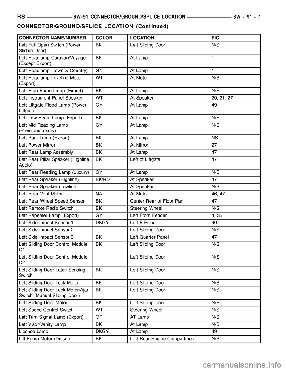
CONNECTOR NAME/NUMBER COLOR LOCATION FIG.
Left Full Open Switch (Power
Sliding Door)BK Left Sliding Door N/S
Left Headlamp Caravan/Voyager
(Except Export)BK At Lamp 1
Left Headlamp (Town & Country) GN At Lamp 1
Left Headlamp Leveling Motor
(Export)WT At Motor N/S
Left High Beam Lamp (Export) BK At Lamp N/S
Left Instrument Panel Speaker WT At Speaker 20, 21, 27
Left Liftgate Flood Lamp (Power
Liftgate)GY At Lamp 49
Left Low Beam Lamp (Export) BK At Lamp N/S
Left Mid Reading Lamp
(Premium/Luxury)GY At Lamp N/S
Left Park Lamp (Export) BK At Lamp NS
Left Power Mirror BK At Mirror 27
Left Rear Lamp Assembly BK At Lamp 47
Left Rear Pillar Speaker (Highline
Audio)BK Left of Liftgate 47
Left Rear Reading Lamp (Luxury) GY At Lamp N/S
Left Rear Speaker (Highline) BK/RD At Speaker 47
Left Rear Speaker (Lowline) At Speaker N/S
Left Rear Vent Motor NAT At Motor 46, 47
Left Rear Wheel Speed Sensor BK Center Rear of Floor Pan 47
Left Remote Radio Switch BK Steering Wheel N/S
Left Repeater Lamp (Export) GY Left Front Fender 4, 36
Left Side Impact Sensor 1 DKGY Left B Pillar 40
Left Side Impact Sensor 2 Left Sliding Door N/S
Left Side Impact Sensor 3 BK Left Quarter Panel 47
Left Sliding Door Control Module
C1BK Left Sliding Door N/S
Left Sliding Door Control Module
C2Left Sliding Door N/S
Left Sliding Door Latch Sensing
SwitchBK Left Sliding Door N/S
Left Sliding Door Lock Motor BK Left Sliding Door N/S
Left Sliding Door Lock Motor/Ajar
Switch (Manual Sliding Door)BK Left Sliding Door N/S
Left Sliding Door Motor BK Left Sliding Door N/S
Left Speed Control Switch WT Steering Wheel N/S
Left Turn Signal Lamp (Export) OR AT Lamp N/S
Left Visor/Vanity Lamp BK At Lamp N/S
License Lamp DKGY At Lamp 49
Lift Pump Motor (Diesel) BK Left Rear Engine Compartment N/S
RS8W-91 CONNECTOR/GROUND/SPLICE LOCATION8W-91-7
CONNECTOR/GROUND/SPLICE LOCATION (Continued)
Page 1123 of 2339
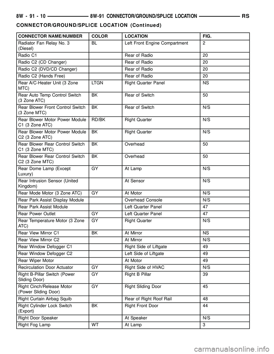
CONNECTOR NAME/NUMBER COLOR LOCATION FIG.
Radiator Fan Relay No. 3
(Diesel)BL Left Front Engine Compartment 2
Radio C1 Rear of Radio 20
Radio C2 (CD Changer) Rear of Radio 20
Radio C2 (DVD/CD Changer) Rear of Radio 20
Radio C2 (Hands Free) Rear of Radio 20
Rear A/C-Heater Unit (3 Zone
MTC)LTGN Right Quarter Panel NS
Rear Auto Temp Control Switch
(3 Zone ATC)BK Rear of Switch 50
Rear Blower Front Control Switch
(3 Zone MTC)BK Rear of Switch N/S
Rear Blower Motor Power Module
C1 (3 Zone ATC)RD/BK Right Quarter N/S
Rear Blower Motor Power Module
C2 (3 Zone ATC)BK Right Quarter N/S
Rear Blower Rear Control Switch
C1 (3 Zone MTC)BK Overhead 50
Rear Blower Rear Control Switch
C2 (3 Zone MTC)BK Overhead 50
Rear Dome Lamp (Except
Luxury)GY At Lamp N/S
Rear Intrusion Sensor (United
Kingdom)At Sensor N/S
Rear Mode Motor (3 Zone ATC) GY At Motor N/S
Rear Park Assist Display Module Overhead Console N/S
Rear Park Assist Module Left Quarter Panel 47
Rear Power Outlet GY Left Quarter Panel 47
Rear Temperature Motor (3 Zone
ATC)GY Right Quarter N/S
Rear View Mirror C1 BK At Mirror NS
Rear View Mirror C2 At Mirror N/S
Rear Window Defogger C1 Right Side of Liftgate 49
Rear Window Defogger C2 Left Side of Liftgate 49
Rear Wiper Motor At Motor 49
Recirculation Door Actuator GY Right Side of HVAC N/S
Right B-Pillar Switch (Power
Sliding Door)GY Right B Pillar 39
Right Cinch/Release Motor
(Power Sliding Door)GY Right Sliding Door 45
Right Curtain Airbag Squib Rear of Right Roof Rail 48
Right Cylinder Lock Switch
(Export)BK Right Front Door 44
Right Door Speaker At Speaker N/S
Right Fog Lamp WT At Lamp 3
8W - 91 - 10 8W-91 CONNECTOR/GROUND/SPLICE LOCATIONRS
CONNECTOR/GROUND/SPLICE LOCATION (Continued)
Page 1124 of 2339
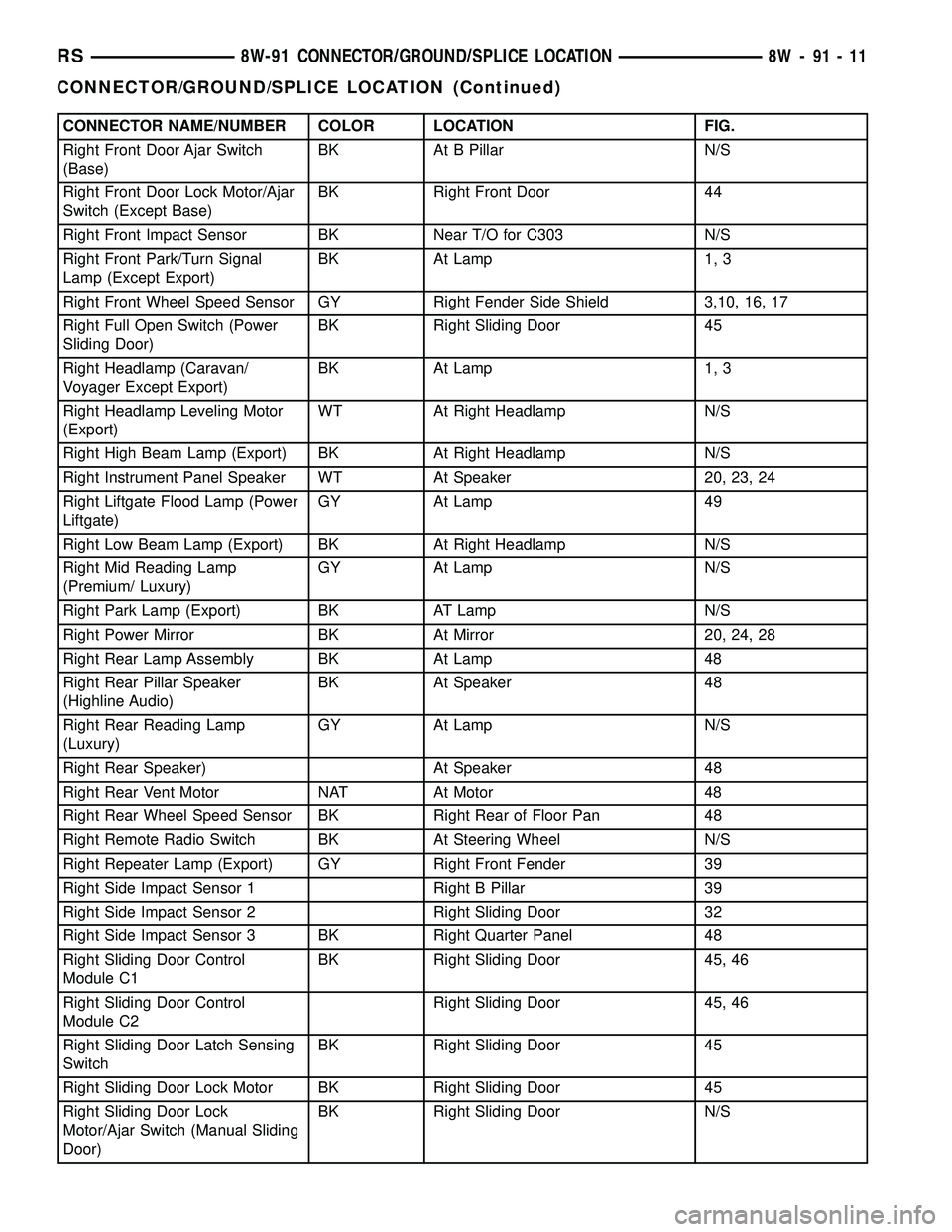
CONNECTOR NAME/NUMBER COLOR LOCATION FIG.
Right Front Door Ajar Switch
(Base)BK At B Pillar N/S
Right Front Door Lock Motor/Ajar
Switch (Except Base)BK Right Front Door 44
Right Front Impact Sensor BK Near T/O for C303 N/S
Right Front Park/Turn Signal
Lamp (Except Export)BK At Lamp 1, 3
Right Front Wheel Speed Sensor GY Right Fender Side Shield 3,10, 16, 17
Right Full Open Switch (Power
Sliding Door)BK Right Sliding Door 45
Right Headlamp (Caravan/
Voyager Except Export)BK At Lamp 1, 3
Right Headlamp Leveling Motor
(Export)WT At Right Headlamp N/S
Right High Beam Lamp (Export) BK At Right Headlamp N/S
Right Instrument Panel Speaker WT At Speaker 20, 23, 24
Right Liftgate Flood Lamp (Power
Liftgate)GY At Lamp 49
Right Low Beam Lamp (Export) BK At Right Headlamp N/S
Right Mid Reading Lamp
(Premium/ Luxury)GY At Lamp N/S
Right Park Lamp (Export) BK AT Lamp N/S
Right Power Mirror BK At Mirror 20, 24, 28
Right Rear Lamp Assembly BK At Lamp 48
Right Rear Pillar Speaker
(Highline Audio)BK At Speaker 48
Right Rear Reading Lamp
(Luxury)GY At Lamp N/S
Right Rear Speaker) At Speaker 48
Right Rear Vent Motor NAT At Motor 48
Right Rear Wheel Speed Sensor BK Right Rear of Floor Pan 48
Right Remote Radio Switch BK At Steering Wheel N/S
Right Repeater Lamp (Export) GY Right Front Fender 39
Right Side Impact Sensor 1 Right B Pillar 39
Right Side Impact Sensor 2 Right Sliding Door 32
Right Side Impact Sensor 3 BK Right Quarter Panel 48
Right Sliding Door Control
Module C1BK Right Sliding Door 45, 46
Right Sliding Door Control
Module C2Right Sliding Door 45, 46
Right Sliding Door Latch Sensing
SwitchBK Right Sliding Door 45
Right Sliding Door Lock Motor BK Right Sliding Door 45
Right Sliding Door Lock
Motor/Ajar Switch (Manual Sliding
Door)BK Right Sliding Door N/S
RS8W-91 CONNECTOR/GROUND/SPLICE LOCATION8W-91-11
CONNECTOR/GROUND/SPLICE LOCATION (Continued)
Page 1125 of 2339
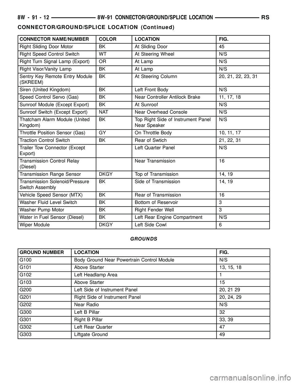
CONNECTOR NAME/NUMBER COLOR LOCATION FIG.
Right Sliding Door Motor BK At Sliding Door 45
Right Speed Control Switch WT At Steering Wheel N/S
Right Turn Signal Lamp (Export) OR At Lamp N/S
Right Visor/Vanity Lamp BK At Lamp N/S
Sentry Key Remote Entry Module
(SKREEM)BK At Steering Column 20, 21, 22, 23, 31
Siren (United Kingdom) BK Left Front Body N/S
Speed Control Servo (Gas) BK Near Controller Antilock Brake 11, 17, 18
Sunroof Module (Except Export) BK At Sunroof N/S
Sunroof Switch (Except Export) NAT Near Overhead Console N/S
Thatcham Alarm Module (United
Kingdom)BK Top Right Side of Instrument Panel
Near SpeakerN/S
Throttle Position Sensor (Gas) GY On Throttle Body 10, 11, 17
Traction Control Switch BK Rear of Swtich 21, 22, 31
Trailer Tow Connector (Except
Export)Left Quarter Panel N/S
Transmission Control Relay
(Diesel)Near Transmission 16
Transmission Range Sensor DKGY Top of Transmission 14, 19
Transmission Solenoid/Pressure
Switch AssemblyBK Side of Transmission 14, 19
Vehicle Speed Sensor (MTX) BK Rear of Transmission 16
Washer Fluid Level Switch BK Bottom of Reservoir 3
Washer Pump Motor BK Right Fender Well 3
Water in Fuel Sensor (Diesel) BK Left Rear Engine Compartment N/S
Wiper Module DKGY Left Side Cowl 6
GROUNDS
GROUND NUMBER LOCATION FIG.
G100 Body Ground Near Powertrain Control Module N/S
G101 Above Starter 13, 15, 18
G102 Left Headlamp Area 1
G103 Above Starter 15
G200 Left Side of Instrument Panel 20, 21 29
G201 Right Side of Instrument Panel 20, 24, 29
G202 Near Radio N/S
G300 Left B Pillar 32
G301 Right B Pillar 33, 39
G302 Left Rear Quarter 47
G303 Liftgate Ground 49
8W - 91 - 12 8W-91 CONNECTOR/GROUND/SPLICE LOCATIONRS
CONNECTOR/GROUND/SPLICE LOCATION (Continued)
Page 1431 of 2339
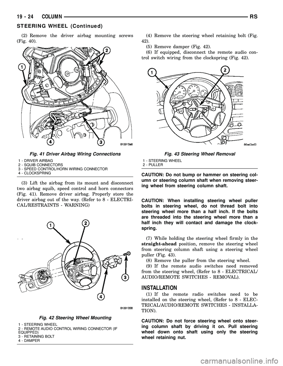
(2) Remove the driver airbag mounting screws
(Fig. 40).
(3) Lift the airbag from its mount and disconnect
two airbag squib, speed control and horn connectors
(Fig. 41). Remove driver airbag. Properly store the
driver airbag out of the way. (Refer to 8 - ELECTRI-
CAL/RESTRAINTS - WARNING)(4) Remove the steering wheel retaining bolt (Fig.
42).
(5) Remove damper (Fig. 42).
(6) If equipped, disconnect the remote audio con-
trol switch wiring from the clockspring (Fig. 42).
CAUTION: Do not bump or hammer on steering col-
umn or steering column shaft when removing steer-
ing wheel from steering column shaft.
CAUTION: When installing steering wheel puller
bolts in steering wheel, do not thread bolt into
steering wheel more than a half inch. If the bolts
are threaded into the steering wheel more than a
half inch they will contact and damage the clock-
spring.
(7) While holding the steering wheel firmly in the
straight-aheadposition, remove the steering wheel
from steering column shaft using a steering wheel
puller (Fig. 43).
(8) Remove the puller from the steering wheel.
(9) If the remote audio switches need removed
from the steering wheel, (Refer to 8 - ELECTRICAL/
AUDIO/REMOTE SWITCHES - REMOVAL).
INSTALLATION
(1) If the remote radio switches need to be
installed on the steering wheel, (Refer to 8 - ELEC-
TRICAL/AUDIO/REMOTE SWITCHES - INSTALLA-
TION).
CAUTION: Do not force steering wheel onto steer-
ing column shaft by driving it on. Pull steering
wheel down onto shaft using only the steering
wheel retaining nut.
Fig. 41 Driver Airbag Wiring Connections
1 - DRIVER AIRBAG
2 - SQUIB CONNECTORS
3 - SPEED CONTROL/HORN WIRING CONNECTOR
4 - CLOCKSPRING
Fig. 42 Steering Wheel Mounting
1 - STEERING WHEEL
2 - REMOTE AUDIO CONTROL WIRING CONNECTOR (IF
EQUIPPED)
3 - RETAINING BOLT
4 - DAMPER
Fig. 43 Steering Wheel Removal
1 - STEERING WHEEL
2 - PULLER
19 - 24 COLUMNRS
STEERING WHEEL (Continued)
Page 1767 of 2339
OPERATION
The Tire Pressure Monitoring (TPM) system uses
radio and sensor technology to monitor tire air pres-
sure levels. Sensors, mounted to each road wheel as
part of the valve stem, transmit a low frequency indi-
cating their individual pressure to a receiver located
in the Wireless Control Module (WCM) portion of the
Sentry Key Remote Electronic Entry Module
(SKREEM). These transmissions occur approximately
once every minute at speeds over 20 mph (32 km/h).
The Tire Pressure Monitoring system remains active
even if no tire pressure related message is displayed.
The sensors lay dormant (Park Mode), then wake
and start transmitting (Drive Mode) when the vehicle
first reaches speeds over 20 mph (32 km/h). Once the
wheels stop rotating for a period of approximately 30
minutes, the sensors shut down until again awaken.
Although not transmitting as when in Drive Mode,
while in Park Mode, the sensors still transmit
approximately once every 13 hours to let the receiver
know air pressure status at that time.
The receiver only receives information from the
four rotating tires. A fifth sensor may be located in
the spare tire wheel, depending on vehicle options.
Although this fifth sensor may be present, it does not
broadcast any information because it does not rotate.
When the system detects that a tire is going low,
below the Low Pressure (lamp) ON Threshold (See
following table), the driver is alerted to the situation.
The Base system illuminates an indicator lamp,
warning the driver of a pressure issue and sounds an
audible chime. In equipped with the Premium sys-
tem, the information is also displayed on the Elec-
tronic Vehicle Information Center (EVIC).
Once pressure in the suspect tire raises above the
Low Pressure (lamp) OFF Threshold, the lamp will
go out and the system returns to normal.
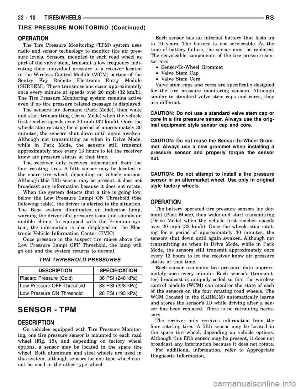
TPM THRESHOLD PRESSURES
DESCRIPTION SPECIFICATION
Placard Pressure (Cold) 36 PSI (248 kPa)
Low Pressure OFF Threshold 33 PSI (228 kPa)
Low Pressure ON Threshold 28 PSI (193 kPa)
SENSOR - TPM
DESCRIPTION
On vehicles equipped with Tire Pressure Monitor-
ing, one tire pressure sensor is mounted to each road
wheel (Fig. 18), and depending on factory wheel
options, a sensor may be located in the spare tire
wheel. Both aluminum and steel wheels are used in
this system, although sensors for one type wheel can-
not be used in the other type wheel.Each sensor has an internal battery that lasts up
to 10 years. The battery is not serviceable. At the
time of battery failure, the sensor must be replaced.
The serviceable components of the tire pressure sen-
sor are:
²Sensor-To-Wheel Grommet
²Valve Stem Cap
²Valve Stem Core
Valve stem caps and cores are specifically designed
for the tire pressure monitoring sensors. Although
similar to standard valve stem caps and cores, they
are different.
CAUTION: Do not use a standard valve stem cap or
core in a tire pressure sensor. Always use the orig-
inal equipment style sensor cap and core.
CAUTION: Do not reuse the Sensor-To-Wheel Grom-
met. Always use a new grommet when installing a
pressure sensor and properly torque the sensor
nut.
CAUTION: Do not attempt to install a tire pressure
sensor in an aftermarket wheel. Use only in original
style factory wheels.
OPERATION
The battery operated tire pressure sensors lay dor-
mant (Park Mode), then wake and start transmitting
(Drive Mode) when the vehicle first reaches speeds
over 20 mph (32 km/h). Once the wheels stop rotat-
ing for a period of approximately 30 minutes, the
sensors shut down until again awaken. Although not
transmitting as when in Drive Mode, while in Park
Mode, the sensors still transmit approximately once
every 13 hours to let the receiver know air pressure
status at that time.
Each sensor transmits tire pressure data approxi-
mately once every minute. Each sensor's (transmit-
ter) broadcast is uniquely coded so that the wireless
control module (WCM) can monitor the state of each
of the sensors on the four rotating road wheels. The
WCM (located in the SKREEM) automatically learns
and stores the sensor's ID while driving after a sen-
sor has been replaced. There is no retraining neces-
sary.
The receiver only receives information from the
four rotating tires. A fifth sensor may be located in
the spare tire wheel, depending on vehicle options.
Although this fifth sensor may be present, it does not
broadcast any information because it does not rotate.
For additional information, refer to Appropriate
Diagnostic Information.
22 - 10 TIRES/WHEELSRS
TIRE PRESSURE MONITORING (Continued)