2005 CHRYSLER CARAVAN oil change
[x] Cancel search: oil changePage 1692 of 2339
stick closely. If there is any doubt about its condition,
drain out a sample for a double check.
MopartATF+4 (Automatic Transmission Fluid)
when new is red in color. The ATF is dyed red so it
can be identified from other fluids used in the vehicle
such as engine oil or antifreeze. The red color is not
permanent and is not an indicator of fluid condition.
As the vehicle is driven, the ATF will begin to look
darker in color and may eventually become brown.
This is normal.ATF+4 also has a unique odor that
may change with age. Consequently,odor and color
cannot be used to indicate the fluid condition
or the need for a fluid change.
After the fluid has been checked, seat the dipstick
fully to seal out water and dirt.STANDARD PROCEDURE - FLUID AND FILTER
SERVICE
NOTE: Refer to the maintenance schedules in
LUBRICATION and MAINTENANCE, or the vehicle
owner's manual, for the recommended maintenance
(fluid/filter change) intervals for this transaxle.
NOTE: Only fluids of the type labeled MoparTATF+4
(Automatic Transmission Fluid) should be used. A
filter change should be made at the time of the
transmission oil change. The magnet (on the inside
of the oil pan) should also be cleaned with a clean,
dry cloth.
NOTE: If the transaxle is disassembled for any rea-
son, the fluid and filter should be changed.
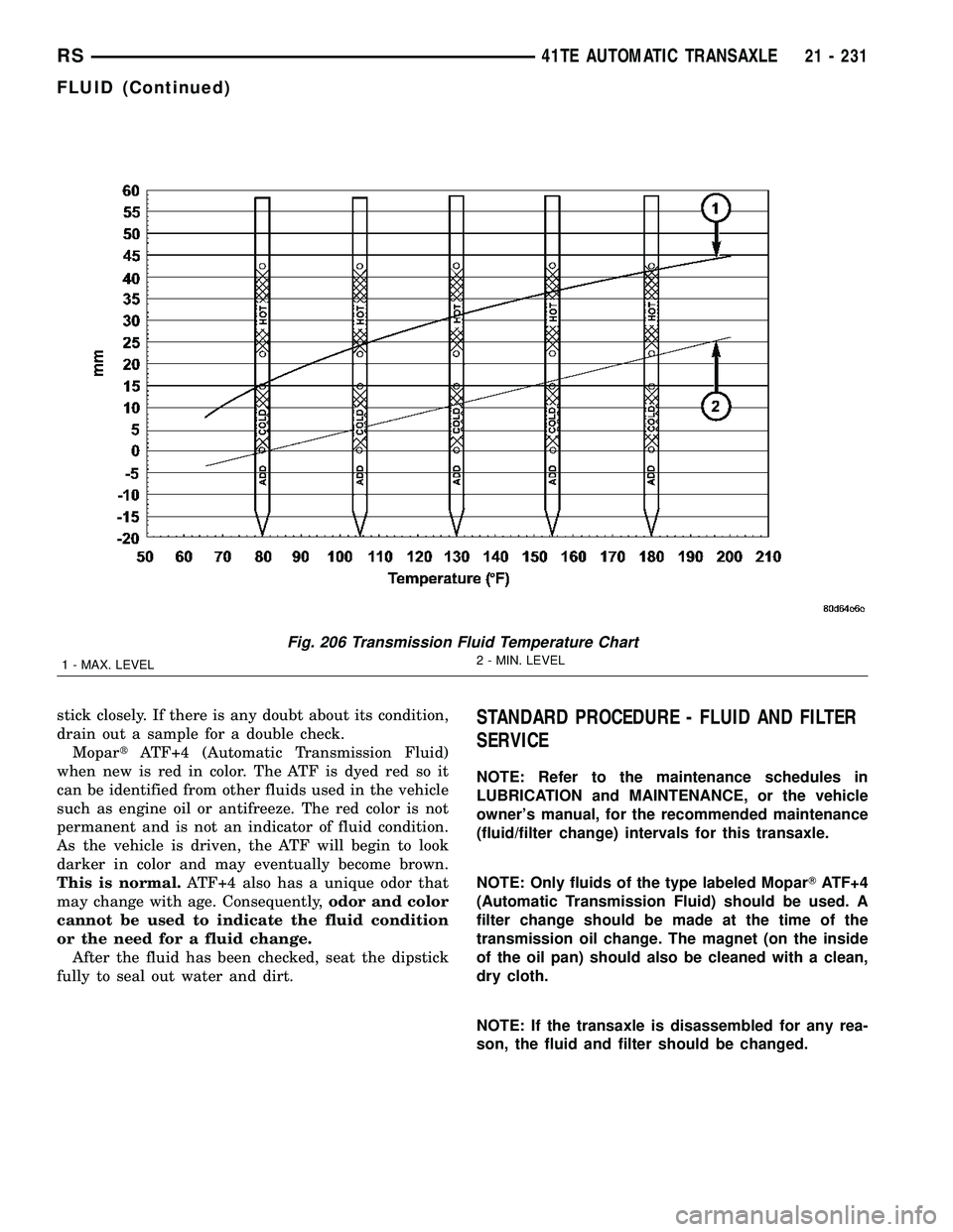
Fig. 206 Transmission Fluid Temperature Chart
1 - MAX. LEVEL2 - MIN. LEVEL
RS41TE AUTOMATIC TRANSAXLE21 - 231
FLUID (Continued)
Page 1724 of 2339
(8) Position an appropriate piece of Plastigage
across both pump gears.
(9) Align the Plastigage to a flat area on the reac-
tion shaft support housing.
(10) Install the reaction shaft to the pump housing
(Fig. 280). Tighten the bolts to 27 N´m (20 ft. lbs.).
(11) Remove bolts and carefully separate the hous-
ings. Measure the Plastigage following the instruc-
tions supplied.
(12) Clearance between both gear end faces and
the reaction shaft support should be 0.020-0.046 mm
(0.0008-0.0018 in.).
ASSEMBLY
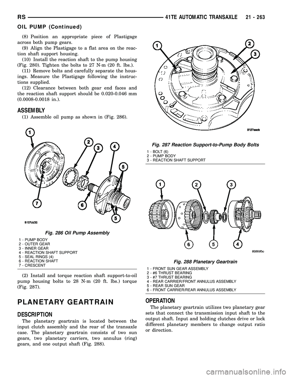
(1) Assemble oil pump as shown in (Fig. 286).
(2) Install and torque reaction shaft support-to-oil
pump housing bolts to 28 N´m (20 ft. lbs.) torque
(Fig. 287).
PLANETARY GEARTRAIN
DESCRIPTION
The planetary geartrain is located between the
input clutch assembly and the rear of the transaxle
case. The planetary geartrain consists of two sun
gears, two planetary carriers, two annulus (ring)
gears, and one output shaft (Fig. 288).
OPERATION
The planetary geartrain utilizes two planetary gear
sets that connect the transmission input shaft to the
output shaft. Input and holding clutches drive or lock
different planetary members to change output ratio
or direction.
Fig. 286 Oil Pump Assembly
1 - PUMP BODY
2 - OUTER GEAR
3 - INNER GEAR
4 - REACTION SHAFT SUPPORT
5 - SEAL RINGS (4)
6 - REACTION SHAFT
7 - CRESCENT
Fig. 287 Reaction Support-to-Pump Body Bolts
1 - BOLT (6)
2 - PUMP BODY
3 - REACTION SHAFT SUPPORT
Fig. 288 Planetary Geartrain
1 - FRONT SUN GEAR ASSEMBLY
2 - #6 THRUST BEARING
3 - #7 THRUST BEARING
4 - REAR CARRIER/FRONT ANNULUS ASSEMBLY
5 - REAR SUN GEAR
6 - FRONT CARRIER/REAR ANNULUS ASSEMBLY
RS41TE AUTOMATIC TRANSAXLE21 - 263
OIL PUMP (Continued)
Page 2188 of 2339
²The normally open terminal (87) provides a bat-
tery current output to the blower motor resistor
(manual heater-A/C control) or blower power module
(ATC heater-A/C control) through a fuse in the IPM
on the fused rear blower motor relay output circuit
only when the blower motor relay coil is energized.
²The normally closed terminal (87A) is not con-
nected to any circuit in this application, but provides
a battery current output only when the rear blower
motor relay coil is de-energized.
Refer to the appropriate wiring information for
diagnosis and testing of the micro-relay and for com-
plete HVAC wiring diagrams.
REMOVAL
(1) Disconnect and isolate the negative battery
cable.
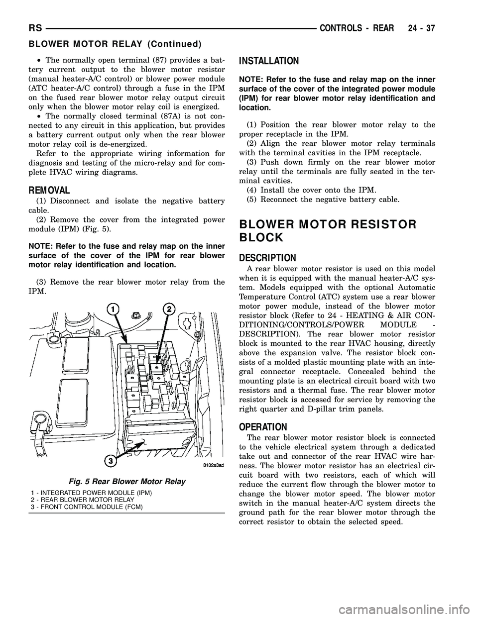
(2) Remove the cover from the integrated power
module (IPM) (Fig. 5).
NOTE: Refer to the fuse and relay map on the inner
surface of the cover of the IPM for rear blower
motor relay identification and location.
(3) Remove the rear blower motor relay from the
IPM.
INSTALLATION
NOTE: Refer to the fuse and relay map on the inner
surface of the cover of the integrated power module
(IPM) for rear blower motor relay identification and
location.
(1) Position the rear blower motor relay to the
proper receptacle in the IPM.
(2) Align the rear blower motor relay terminals
with the terminal cavities in the IPM receptacle.
(3) Push down firmly on the rear blower motor
relay until the terminals are fully seated in the ter-
minal cavities.
(4) Install the cover onto the IPM.
(5) Reconnect the negative battery cable.
BLOWER MOTOR RESISTOR
BLOCK
DESCRIPTION
A rear blower motor resistor is used on this model
when it is equipped with the manual heater-A/C sys-
tem. Models equipped with the optional Automatic
Temperature Control (ATC) system use a rear blower
motor power module, instead of the blower motor
resistor block (Refer to 24 - HEATING & AIR CON-
DITIONING/CONTROLS/POWER MODULE -
DESCRIPTION). The rear blower motor resistor
block is mounted to the rear HVAC housing, directly
above the expansion valve. The resistor block con-
sists of a molded plastic mounting plate with an inte-
gral connector receptacle. Concealed behind the
mounting plate is an electrical circuit board with two
resistors and a thermal fuse. The rear blower motor
resistor block is accessed for service by removing the
right quarter and D-pillar trim panels.
OPERATION
The rear blower motor resistor block is connected
to the vehicle electrical system through a dedicated
take out and connector of the rear HVAC wire har-
ness. The blower motor resistor has an electrical cir-
cuit board with two resistors, each of which will
reduce the current flow through the blower motor to
change the blower motor speed. The blower motor
switch in the manual heater-A/C system directs the
ground path for the rear blower motor through the
correct resistor to obtain the selected speed.
Fig. 5 Rear Blower Motor Relay
1 - INTEGRATED POWER MODULE (IPM)
2 - REAR BLOWER MOTOR RELAY
3 - FRONT CONTROL MODULE (FCM)
RSCONTROLS - REAR24-37
BLOWER MOTOR RELAY (Continued)
Page 2223 of 2339
(4) Open both the suction and discharge valves,
then open the charge valve to allow the heated
refrigerant to flow into the system.
(5) When the transfer of refrigerant has stopped,
close both the suction and discharge valves.
(6) If all of the refrigerant charge did not transfer
from the dispensing device, open all of the windows
in the vehicle and set the heater-air conditioner con-
trols so that the compressor is engaged and the
blower motor is operating at its lowest speed setting.
Run the engine at a steady high idle (about 1400
rpm). If the compressor will not engage, test the com-
pressor clutch control circuit and repair as required.
(7) Open the suction valve to allow the remaining
refrigerant to transfer to the refrigerant system.
WARNING: TAKE CARE NOT TO OPEN THE DIS-
CHARGE (HIGH PRESSURE) VALVE AT THIS TIME.
(8) Close the suction valve and test the system
performance. (Refer to 24 - HEATING & AIR CON-
DITIONING - STANDARD PROCEDURE - A/C PER-
FORMANCE TEST).
(9) Disconnect the charging station and manifold
gauge set from the refrigerant system service ports.
(10) Reinstall the caps onto the refrigerant system
service ports.
(11) Run the HVAC Control Cooldown test to ver-
ify proper operation(Refer to 24 - HEATING & AIR
CONDITIONING - DIAGNOSIS AND TESTING).
A/C COMPRESSOR
DESCRIPTION
A/C COMPRESSOR
Vehicles equipped with the 2.4L gasoline, 2.5L die-
sel, 2.8L diesel and 3.3L gasoline engines with the
front heating-A/C system only, use the Denso 10S17
A/C compressor. Vehicles equipped with the 3.3L and
the 3.8L gasoline engines with the optional rear heat-
ing-A/C system use the Denso 10S20 A/C compressor.
Both A/C compressors include an integral high pres-
sure relief valve. The A/C compressor is secured to a
mounting bracket on the 2.4L gasoline engine and
directly to the cylinder block on the 2.5L diesel, 2.8L
diesel, 3.3L gasoline and 3.8L gasoline engines.
HIGH PRESSURE RELIEF VALVE
A high pressure relief valve is located on the rear
of the A/C compressor. This mechanical valve is
designed to vent refrigerant from the A/C system to
protect against damage to the compressor and other
system components, caused by condenser air flow
restriction or an overcharge of refrigerant.
OPERATION
A/C COMPRESSOR
The A/C compressor is driven by the engine
through an electric clutch, drive pulley and belt
arrangement. The compressor is lubricated by refrig-
erant oil that is circulated throughout the refrigerant
system with the refrigerant.
The compressor draws in low-pressure refrigerant
vapor from the evaporator through its suction port. It
then compresses the refrigerant into a high-pressure,
high-temperature refrigerant vapor. The compressor
pumps the high-pressure refrigerant vapor to the
condenser through the compressor discharge port.
The compressor cannot be repaired. If faulty or
damaged, the entire compressor assembly must be
replaced. The compressor clutch, pulley and clutch
coil are available for service.
HIGH PRESSURE RELIEF VALVE
The high pressure relief valve vents the system
when a discharge pressure of 3445 to 4135 kPa (500
to 600 psi) or above is reached. The valve closes
when a minimum discharge pressure of 2756 kPa
(400 psi) is reached.
The high pressure relief valve vents only enough
refrigerant to reduce the system pressure, and then
re-seats itself. The majority of the refrigerant is con-
served in the system. If the valve vents refrigerant, it
does not mean that the valve is faulty.
The high pressure relief valve is a factory-cali-
brated unit. The valve cannot be adjusted or
repaired, and must not be removed or otherwise dis-
turbed. The valve is only serviced as a part of the
compressor assembly.
DIAGNOSIS AND TESTING
A/C COMPRESSOR NOISE DIAGNOSIS
Excessive noise while the air conditioning compres-
sor is operating can be caused by loose compressor
mounts, a loose compressor clutch, or high operating
pressures in the refrigerant system. Verify compres-
sor drive belt condition, proper compressor mounting,
correct refrigerant charge level, and compressor head
pressure before compressor repair is performed.
With the close tolerances within the compressor, it
is possible to experience a temporary lockup. The
longer the compressor is inactive, the more likely the
condition is to occur. This condition is the result of
normal refrigerant migration within the refrigerant
system caused by ambient temperature changes. The
refrigerant migration may wash the refrigerant oil
out of the compressor.
24 - 72 PLUMBING - FRONTRS
PLUMBING - FRONT (Continued)
Page 2226 of 2339
²The upper bolt at the rear of the compressor.
²The lower bolt at the rear of the compressor.
(4) Connect the wire harness connector to the com-
pressor clutch coil wire connector.
(5) Install the accessory drive belt (Refer to 7 -
COOLING/ACCESSORY DRIVE/DRIVE BELTS -
INSTALLATION).
(6) Lower the vehicle.
(7) Remove the tape or plugs from the suction and
discharge line fittings and the compressor ports.
(8) Lubricate new rubber O-ring seals with clean
refrigerant oil and install them and a new gasket
onto the suction and discharge line fittings.
(9) Connect the A/C suction line and the A/C dis-
charge line to the A/C compressor.
(10) Install the nut that secures the A/C suction
line and the A/C discharge line to the A/C compres-
sor. Tighten the nuts to 23 N´m (17 ft. lbs.).
(11) Reconnect the negative battery cable.
(12) Evacuate the refrigerant system (Refer to 24 -
HEATING & AIR CONDITIONING/PLUMBING -
FRONT/REFRIGERANT - STANDARD PROCE-
DURE - REFRIGERANT SYSTEM EVACUATE).
(13) Charge the refrigerant system (Refer to 24 -
HEATING & AIR CONDITIONING/PLUMBING -
FRONT/REFRIGERANT - STANDARD PROCE-
DURE - REFRIGERANT SYSTEM CHARGE).
A/C COMPRESSOR MOUNTING BRACKET -
2.4L ENGINE
(1) Position the compressor mounting bracket onto
the engine.
(2) Install the four bolts that secure the compres-
sor mounting bracket to the engine. Tighten the bolts
to 54 N´m (40 ft. lbs.).
(3) Reinstall the A/C compressor onto the mount-
ing bracket (Refer to 24 - HEATING & AIR CONDI-
TIONING/PLUMBING/COMPRESSOR -
INSTALLATION).
A/C CONDENSER
DESCRIPTION
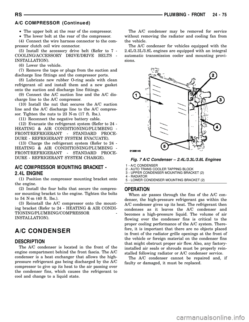
The A/C condenser is located in the front of the
engine compartment behind the front fascia. The A/C
condenser is a heat exchanger that allows the high-
pressure refrigerant gas being discharged by the A/C
compressor to give up its heat to the air passing over
the condenser fins, which causes the refrigerant to
cool and change to a liquid state.The A/C condenser may be removed for service
without removing the radiator and cooling fan from
the vehicle.
The A/C condenser for vehicles equipped with the
2.4L/3.3L/3.8L engines are equipped with an integral
automatic transmission cooler and mounting provi-
sions.
OPERATION
When air passes through the fins of the A/C con-
denser, the high-pressure refrigerant gas within the
A/C condenser gives up its heat. The refrigerant then
condenses as it leaves the A/C condenser and
becomes a high-pressure liquid. The volume of air
flowing over the condenser fins is critical to the
proper cooling performance of the A/C system. There-
fore, it is important that there are no objects placed
in front of the radiator grille openings at the front of
the vehicle or foreign material on the condenser fins
that might obstruct proper air flow. Also, any factory-
installed air seals or shrouds must be properly rein-
stalled following radiator or A/C condenser service.
The A/C condenser cannot be repaired and, if
faulty or damaged, it must be replaced.
Fig. 7 A/C Condenser ± 2.4L/3.3L/3.8L Engines
1 - A/C CONDENSER
2 - AUTO TRANS COOLER TAPPING BLOCK
3 - UPPER CONDENSER MOUNTING BRACKET (2)
4 - RADIATOR
5 - LOWER CONDENSER MOUNTING BRACKET (2)
RSPLUMBING - FRONT24-75
A/C COMPRESSOR (Continued)
Page 2234 of 2339
(13) Install plugs in, or tape over the opened suc-
tion line and liquid line fittings and both expansion
valve ports.
(14) Remove the two screws that secure the A/C
expansion valve to the evaporator tube tapping plate.
(15) On RG models, disconnect the HVAC wire
harness connector from the evaporator temperature
sensor.
(16) Remove the A/C expansion valve from the
evaporator inlet and outlet tube fittings.
(17) Remove the seals from the evaporator inlet
and outlet tube fittings and discard.
(18) Install plugs in, or tape over the opened evap-
orator inlet and outlet tube fittings and both expan-
sion valve ports.
(19) On RG models, remove the evaporator tem-
perature sensor retainer and evaporator temperature
sensor from the A/C expansion valve, if required.
INSTALLATION
NOTE: Any grease removed with the evaporator
temperature sensor must be replaced. Failure to do
so could result in poor A/C performance.
(1) On RG models, install the evaporator tempera-
ture sensor and retainer onto the A/C expansion
valve, if removed.
(2) Remove the tape or plugs from the evaporator
inlet and outlet tube fittings and both ports on the
back of the A/C expansion valve.(3) Lubricate new rubber O-ring seals with clean
refrigerant oil and install them on the evaporator
inlet and outlet tube fittings.
(4) Position the A/C expansion valve onto the evap-
orator inlet and outlet tube fittings.
(5) Install the two screws that secure the A/C
expansion valve to the evaporator tube tapping plate
plate. Tighten the screws to 11 N´m (97 in. lbs.).
(6) On RG models, connect the HVAC wire harness
connector to the evaporator temperature sensor.
(7) Remove the tape or plugs from the front liquid
line rear section and suction line fittings for the
expansion valve and both ports on the front of the
expansion valve.
(8) Lubricate new rubber O-ring seals with clean
refrigerant oil and install them on the front liquid
line rear section and suction line fittings for the
expansion valve.
(9) Connect the liquid line and suction line fittings
to the expansion valve.
(10) Install the nut that secures the suction line
and liquid line fittings to the stud on the expansion
valve. Tighten the nut to 23 N´m (17 ft. lbs.).
(11) Remove the tape or plugs from the liquid line
rear section fitting and the receiver/drier outlet port.
(12) Lubricate a new rubber O-ring seal with clean
refrigerant oil and install it on the liquid line fitting.
(13) Connect the liquid line fitting to the receiver/
drier outlet port.
(14) Install the screw that secures the liquid line
fitting to the receiver/drier. Tighten the screw to 11
N´m (97 in. lbs.).
(15) Connect the wire harness connector to the A/C
pressure transducer.
(16) Connect the drain tube to the wiper module
drain on the right side of the engine compartment.
(17) Install the air cleaner housing.
(18) Reconnect the battery negative cable.
(19) Evacuate the refrigerant system (Refer to 24 -
HEATING & AIR CONDITIONING/PLUMBING -
FRONT/REFRIGERANT - STANDARD PROCE-
DURE - REFRIGERANT SYSTEM EVACUATE).
(20) Charge the refrigerant system (Refer to 24 -
HEATING & AIR CONDITIONING/PLUMBING -
FRONT/REFRIGERANT - STANDARD PROCE-
DURE - REFRIGERANT SYSTEM CHARGE).
HEATER CORE
DESCRIPTION
The heater core is located in the distribution hous-
ing, which is attached to the HVAC housing, behind
the instrument panel. It is a heat exchanger made of
rows of tubes and fins. One end of the core is fitted
with a molded plastic tank, which includes integral
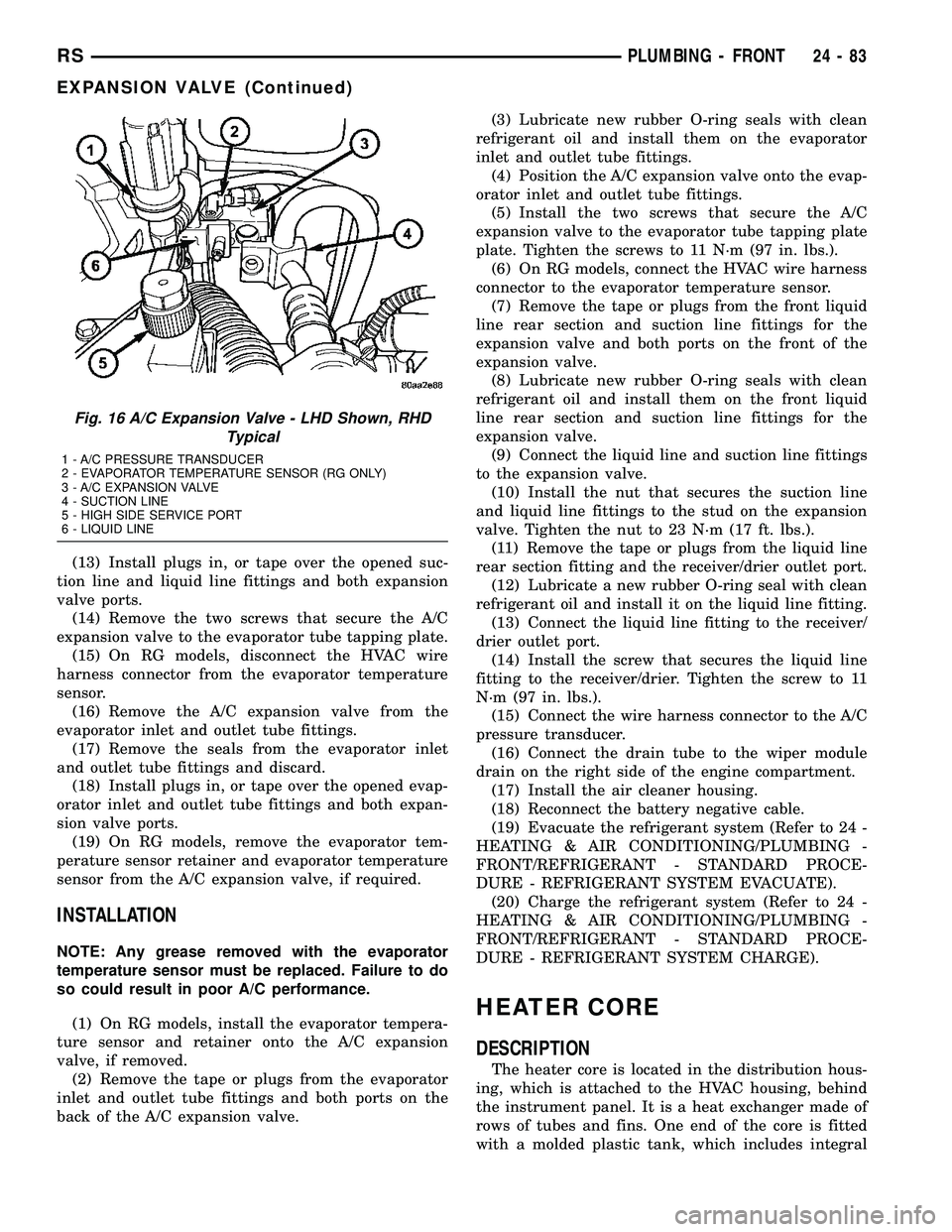
Fig. 16 A/C Expansion Valve - LHD Shown, RHD
Typical
1 - A/C PRESSURE TRANSDUCER
2 - EVAPORATOR TEMPERATURE SENSOR (RG ONLY)
3 - A/C EXPANSION VALVE
4 - SUCTION LINE
5 - HIGH SIDE SERVICE PORT
6 - LIQUID LINE
RSPLUMBING - FRONT24-83
EXPANSION VALVE (Continued)
Page 2275 of 2339
The following is a list of the monitored compo-
nents:
²Catalyst Monitor
²Comprehensive Components
²EGR (if equipped)
²Fuel Control (rich/lean)
²Oxygen Sensor Monitor
²Oxygen Sensor Heater Monitor
²Purge
²Misfire
²Natural Vacuum Leak Detection (NVLD)
COMPREHENSIVE COMPONENTS
Along with the major monitors, OBD II requires
that the diagnostic system monitor any component
that could affect emissions levels. In many cases,
these components were being tested under OBD I.
The OBD I requirements focused mainly on testing
emissions-related components for electrical opens and
shorts.
However, OBD II also requires that inputs from
powertrain components to the PCM be tested for
rationality, and that outputs to powertrain compo-
nents from the PCM be tested forfunctionality.
Methods for monitoring the various Comprehensive
Component monitoring include:
(1) Circuit Continuity
²Open
²Shorted high
²Shorted to ground
(2) Rationality or Proper Functioning
²Inputs tested for rationality
²Outputs tested for functionality
NOTE: Comprehensive component monitors are
continuous. Therefore, enabling conditions do not
apply. All will set a DTC and illuminate the MIL in 1-
trip.
Input RationalityÐWhile input signals to the
PCM are constantly being monitored for electrical
opens and shorts, they are also tested for rationality.
This means that the input signal is compared against
other inputs and information to see if it makes sense
under the current conditions.
PCM sensor inputs that are checked for rationality
include:
²Manifold Absolute Pressure (MAP) Sensor
²Oxygen Sensor (O2S) (slow response)
²Engine Coolant Temperature (ECT) Sensor
²Camshaft Position (CMP) Sensor
²Vehicle Speed Sensor
²Crankshaft Position (CKP) Sensor
²Intake Air Temperature (IAT) Sensor
²Throttle Position (TPS) Sensor
²Ambient/Battery Temperature Sensors
²Power Steering Switch²Oxygen Sensor Heater
²Engine Controller
²Brake Switch
²Natural Vacuum Leak Detection (NVLD)
²P/N Switch
²Trans Controls
Output FunctionalityÐPCM outputs are tested
for functionality in addition to testing for opens and
shorts. When the PCM provides a voltage to an out-
put component, it can verify that the command was
carried out by monitoring specific input signals for
expected changes. For example, when the PCM com-
mands the Idle Air Control (IAC) Motor to a specific
position under certain operating conditions, it expects
to see a specific (target) idle speed (RPM). If it does
not, it stores a DTC.
PCM outputs monitored for functionality include:
²Fuel Injectors
²Ignition Coils
²Torque Converter Clutch Solenoid
²Idle Air Control
²Purge Solenoid
²EGR Solenoid
²Radiator Fan Control
²Trans Controls
OXYGEN SENSOR (O2S) MONITOR
DESCRIPTIONÐEffective control of exhaust
emissions is achieved by an oxygen feedback system.
The most important element of the feedback system
is the O2S. The O2S is located in the exhaust path.
Once it reaches operating temperature 300É to 350ÉC
(572É to 662ÉF), the sensor generates a voltage that
is inversely proportional to the amount of oxygen in
the exhaust. When there is a large amount of oxygen
in the exhaust caused by a lean condition, misfire or
exhaust leak, the sensor produces a low voltage,
below 450 mV. When the oxygen content is lower,
caused by a rich condition, the sensor produces a
higher voltage, above 450mV.
The information obtained by the sensor is used to
calculate the fuel injector pulse width. The PCM is
programmed to maintain the optimum air/fuel ratio.
At this mixture ratio, the catalyst works best to
remove hydrocarbons (HC), carbon monoxide (CO)
and nitrous oxide (NOx) from the exhaust.
The O2S is also the main sensing element for the
EGR, Catalyst and Fuel Monitors, and purge.
The O2S may fail in any or all of the following
manners:
²Slow response rate (Big Slope)
²Reduced output voltage (Half Cycle)
²Heater Performance
Slow Response Rate (Big Slope)ÐResponse rate
is the time required for the sensor to switch from
lean to rich signal output once it is exposed to a
25 - 2 EMISSIONS CONTROLRS
EMISSIONS CONTROL (Continued)
Page 2276 of 2339
richer than optimum A/F mixture or vice versa. As
the PCM adjusts the air/fuel ratio, the sensor must
be able to rapidly detect the change. As the sensor
ages, it could take longer to detect the changes in the
oxygen content of the exhaust gas. The rate of
change that an oxygen sensor experiences is called
'Big Slope'. The PCM checks the oxygen sensor volt-
age in increments of a few milliseconds.
Reduced Output Voltage (Half Cycle)ÐThe
output voltage of the O2S ranges from 0 to 1 volt. A
good sensor can easily generate any output voltage in
this range as it is exposed to different concentrations
of oxygen. To detect a shift in the A/F mixture (lean
or rich), the output voltage has to change beyond a
threshold value. A malfunctioning sensor could have
difficulty changing beyond the threshold value. Many
times the condition is only temporey and the sensor
will recover. Under normal conditions the voltage sig-
nal surpasses the threshold, and a counter is incre-
mented by one. This is called the Half Cycle Counter.
Heater PerformanceÐThe heater is tested by a
separate monitor. Refer to the Oxygen Sensor Heater
Monitor.
OPERATIONÐAs the Oxygen Sensor signal
switches, the PCM monitors the half cycle and big
slope signals from the oxygen sensor. If during the
test neither counter reaches a predetermined value, a
malfunction is entered and a Freeze Frame is stored.
Only one counter reaching its predetermined value is
needed for the monitor to pass.
The Oxygen Sensor Signal Monitor is a two trip
monitor that is tested only once per trip. When the
Oxygen Sensor fails the test in two consecutive trips,
the MIL is illuminated and a DTC is set. The MIL is
extinguished when the Oxygen Sensor monitor
passes in three consecutive trips. The DTC is erased
from memory after 40 consecutive warm-up cycles
without test failure.
Enabling ConditionsÐThe following conditions
must typically be met for the PCM to run the oxygen
sensor monitor:
²Battery voltage
²Engine temperature
²Engine run time
²Engine run time at a predetermined speed
²Engine run time at a predetermined speed and
throttle opening
²Transmission in gear (automatic only)
²Fuel system in Closed Loop
²Long Term Adaptive (within parameters)
²Power Steering Switch in low PSI (no load)
²Engine at idle
²Fuel level above 15%
²Ambient air temperature
²Barometric pressure²Engine RPM within acceptable range of desired
idle
²Closed throttle speed
Pending ConditionsÐThe Task Manager typi-
cally does not run the Oxygen Sensor Signal Monitor
if overlapping monitors are running or the MIL is
illuminated for any of the following:
²Misfire Monitor
²Front Oxygen Sensor and Heater Monitor
²MAP Sensor
²Vehicle Speed Sensor
²Engine Coolant Temperature Sensor
²Throttle Position Sensor
²Engine Controller Self Test Faults
²Cam or Crank Sensor
²Injector and Coil
²Idle Air Control Motor
²EVAP Electrical
²EGR Solenoid Electrical
²Intake Air Temperature
²5 Volt Feed
ConflictÐThe Task Manager does not run the
Oxygen Sensor Monitor if any of the following condi-
tions are present:
²A/C ON (A/C clutch cycling temporarily sus-
pends monitor)
²Purge flow in progress
²Ethenal content learn is taking place and the
ethenal used once flag is set
SuspendÐThe Task Manager suspends maturing
a fault for the Oxygen Sensor Monitor if an of the fol-
lowing are present:
²Oxygen Sensor Heater Monitor, Priority 1
²Misfire Monitor, Priority 2
OXYGEN SENSOR HEATER MONITOR (NGC)
DESCRIPTIONÐIf the Oxygen sensor (O2S) DTC
as well as a O2S heater DTC is present, the O2S
Heater DTC MUST be repaired first. After the O2S
Heater is repaired, verify that the sensor circuit is
operating correctly.
The voltage reading taken from the O2S are very
temperature sensitive. The readings taken from the
O2S are not accurate below 300 degrees C. Heating
the O2S is done to allow the engine controller to shift
to closed loop control as soon as possible. The heating
element used to heat the O2S must be tested to
ensure that it is heating the sensor properly. Starting
with the introduction on the NGC module the strat-
egy for checking the heater circuit has changed. The
heater resistance is checked by the NGC almost
immediately after the engine is started. The same
O2S heater return pin used to read the heater resis-
tance is capable of detecting an open circuit, a
shorted high or shorted low condition.
RSEMISSIONS CONTROL25-3
EMISSIONS CONTROL (Continued)