2005 CHRYSLER CARAVAN display
[x] Cancel search: displayPage 2157 of 2339
defogger function will be active for 10 minutes and
can be turned off by a switch press. The defogger will
function while the control is in the ON mode.
²FAN/MODE± The Fan and Mode knobs have
17 manual selectable positions. Manually changing
either of the rotary knobs for mode or fan speed set-
tings makes control of that blower motor manual. If
only one is changed manually, the other remains
under automatic control. Pressing the HI-AUTO/LO-
AUTO rocker switch restores full automatic control.
²BLOWER DELAY TIMER± The word DELAY
is displayed at start-up to signify that the system is
waiting so that cold air will not be blowing. This tells
the operator that it is unnecessary to turn the sys-
tem off, raise the temperature setting or turn the fan
speed setting down to prevent cold air from blowing.
A countdown in minutes and seconds until the engine
is warm enough to begin delivering heat to the pas-
sengers alternates with the DELAY message at 25
second intervals. This countdown is based on actual
measurement of the rate of engine coolant tempera-
ture change. During the delay time, mix mode is
selected and the fan operates at a low speed to keep
the windshield fog free.
²REAR CONTROL (Three-Zone only)± When
the Rear System control knob is moved to the OFF
position, there will be a delay of approximately 1 sec-
ond before the system actually turns off. This delay
is to prevent an undesired blower dropout if the knob
is moved through OFF to the other selections.
REAR CONTROL PANEL ± THREE ZONE ATC
SYSTEM
Primary control of the rear compartment heating-
A/C system for the Three-Zone ATC system is in the
instrument panel center stack. This control allows
the driver to turn the rear heating-A/C system off, or
allows the intermediate seat occupants control of the
rear system by switching to the REAR position, or
provides fully automatic control based on the temper-
ature setting shown on the front control display.
²REAR CONTROL± Selecting automatic control
of the rear unit at the instrument panel, illuminates
a Locked Padlock in the rear control panel display.
Selecting REAR activates the rear control panel and
the Padlock then appears unlocked.
²FAN KNOB± The rear fan control has Off and
AUTO positions and a range of manual speed set-
tings that override the AUTO setting.
²MODE KNOB± The mode control allows inter-
mediate seat occupants to manually override the
automatic mode and select any balance of air flow
between overhead and floor outlets from full over-
head to full floor.
²SET TEMP± The rear set temp control will
operate identical to the front controls. If the frontcontrol rear set temp button is pressed simulta-
neously with the rear control head, then the front
control head press events shall have priority, i.e. if
the front user presses Rear Set Temp down and the
rear user presses Set Temp up, then the rear set
temp will decrease.
DIAGNOSIS AND TESTING
A/C COOL DOWN TEST
The heater-A/C control module can perform an A/C
cool down test, which is a test performed during the
manufacturing process to confirm that the air condi-
tioning system is performing satisfactorily. This test
can also provide a quick confirmation of air condi-
tioning system performance to the service technician.
If the test is completed satisfactorily, no further ser-
vice is required. If the test is failed, proceed to the
A/C Performance Test to confirm the A/C system is
operating properly, or use a DRBIIItscan tool to
diagnose the A/C system control and distribution sys-
tems. Refer to the appropriate diagnostic informa-
tion.
MANUAL TEMPERATURE CONTROL
The front blower speed and rear blower speed (if
equipped with rear HVAC) must be set to High and
the evaporator temperature sensor must be greater
than 13É C (55É F) or the test will fail immediately.
The test is activated by depressing the A/C and Rear
Wipe/Wash buttons simultaneously and holding them
depressed for no less than five seconds. The Rear
Wipe/Wash and A/C LEDs will blink on and off until
the test is complete. If the LEDs stop blinking before
two minutes, then the cool down test has been com-
pleted successfully. If the two minutes expire without
the expansion valve temperature reaching -6É C (20É
F) less than the outside air temperature, then the
cool down test has been failed and further A/C sys-
tem diagnosis is required. If the test is failed, the
LEDs will continue to blink until the vehicle has
been driven for greater than 13 km (8 miles).
AUTOMATIC TEMPERATURE CONTROL
The ambient air temperature in the room where
the vehicle will be tested must be a minimum of 21É
C (70ÉF) for this test. The test is activated by
depressing the A/C and PWR buttons simultaneously
and holding them depressed for no less than four sec-
onds. The snowflake icon and the DELAY text in the
ATC display will blink on and off alternately until
the test is complete. If the snowflake icon and the
DELAY text stop blinking before two minutes, then
the cool down test has been completed successfully. If
the two minutes expire without the evaporator tem-
perature reaching -6É C (20É F) less than the evapo-
24 - 6 HEATING & AIR CONDITIONINGRS
HEATING & AIR CONDITIONING (Continued)
Page 2274 of 2339
EMISSIONS CONTROL
TABLE OF CONTENTS
page page
EMISSIONS CONTROL
DESCRIPTION
VEHICLE EMISSION CONTROL
INFORMATION LABEL...................1
TRIP DEFINITION......................1
DESCRIPTION - MONITORED COMPONENT . 1
NON-MONITORED CIRCUITS.............5
DESCRIPTION - MONITORED SYSTEMS....6HIGH AND LOW LIMITS.................9
OPERATION
SYSTEM.............................9
DRB IIITSTATE DISPLAY TEST MODE.....10
EVAPORATIVE EMISSIONS................11
EXHAUST GAS RECIRCULATION...........22
ON-BOARD DIAGNOSTICS................25
EMISSIONS CONTROL
DESCRIPTION
VEHICLE EMISSION CONTROL INFORMATION
LABEL
All models have a Vehicle Emission Control Infor-
mation (VECI) Label. Chrysler permanently attaches
the label in the engine compartment. It cannot be
removed without defacing information and destroying
the label.
The label contains the vehicle's emission specifica-
tions and vacuum hose routings. All hoses must be
connected and routed according to the label.
TRIP DEFINITION
A ªTripº means vehicle operation (following an
engine-off period) of duration and driving mode such
that all components and systems are monitored at
least once by the diagnostic system. The monitors
must successfully pass before the PCM can verify
that a previously malfunctioning component is meet-
ing the normal operating conditions of that compo-
nent. For misfire or fuel system malfunction, the
MIL may be extinguished if the fault does not recur
when monitored during three subsequent sequential
driving cycles in which conditions are similar to
those under which the malfunction was first deter-
mined.
Anytime the MIL is illuminated, a DTC is stored.
The DTC can self erase only after the MIL has been
extinguished. Once the MIL is extinguished, the
PCM must pass the diagnostic test for the most
recent DTC for 40 warm-up cycles (80 warm-up
cycles for the Fuel System Monitor and the Misfire
Monitor). A warm-up cycle can best be described by
the following:
²The engine must be running²A rise of 40ÉF in engine temperature must occur
from the time when the engine was started
²Engine coolant temperature must crossover
160ÉF
²A ªdriving cycleº that consists of engine start up
and engine shut off.
Once the above conditions occur, the PCM is con-
sidered to have passed a warm-up cycle. Due to the
conditions required to extinguish the MIL and erase
the DTC, it is most important that after a repair has
been made, all DTC's be erased and the repair veri-
fied by running 1±good trip.
DESCRIPTION - MONITORED COMPONENT
There are several components that will affect vehi-
cle emissions if they malfunction. If one of these com-
ponents malfunctions the Malfunction Indicator
Lamp (Check Engine) will illuminate.
Some of the component monitors are checking for
proper operation of the part. Electrically operated
components now have input (rationality) and output
(functionality) checks as well as continuity tests
(opens/shorts). Previously, a component like the
Throttle Position sensor (TPS) was checked by the
PCM for an open or shorted circuit. If one of these
conditions occurred, a DTC was set. Now there is a
check to ensure that the component is working. This
is done by watching for a TPS indication of a greater
or lesser throttle opening than MAP and engine rpm
indicate. In the case of the TPS, if engine vacuum is
high and engine rpm is 1600 or greater and the TPS
indicates a large throttle opening, a DTC will be set.
The same applies to low vacuum and 1600 rpm.
Any component that has an associated limp in will
set a fault after 1 trip with the malfunction present.
Refer to the Diagnostic Trouble Codes Description
Charts in this section and the appropriate Power-
train Diagnostic Procedure Manual for diagnostic
procedures.
RSEMISSIONS CONTROL25-1
Page 2282 of 2339
as well as allowing sufficient purge flow in the event
that the solenoid was to become inoperative.
The solenoid actuates the valve to unseal the can-
ister vent while the engine is running. It also will be
used to close the vent during the medium and large
leak tests and during the purge flow check. This sole-
noid requires initial 1.5 amps of current to pull the
valve open but after 100 ms. will be duty cycled down
to an average of about 150 mA for the remainder of
the drive cycle.
Another feature in the device is a diaphragm that
will open the seal in the NVLD with pressure in the
evaporative system. The device will9blow off9at
about 0.59H2O (0.12 KPA) pressure to permit the
venting of vapors during refueling. An added benefit
to this is that it will also allow the tank to9breathe9
during increasing temperatures, thus limiting the
pressure in the tank to this low level. This is benefi-
cial because the induced vacuum during a subse-
quent declining temperature will achieve the switch
closed (pass threshold) sooner than if the tank had to
decay from a built up pressure.
The device itself has 3 wires: Switch sense, sole-
noid driver and ground. It also includes a resistor to
protect the switch from a short to battery or a short
to ground. The NGC utilizes a high-side driver to
energize and duty-cycle the solenoid.
HIGH AND LOW LIMITS
The PCM compares input signal voltages from each
input device with established high and low limits for
the device. If the input voltage is not within limits
and other criteria are met, the PCM stores a diagnos-
tic trouble code in memory. Other diagnostic trouble
code criteria might include engine RPM limits or
input voltages from other sensors or switches that
must be present before verifying a diagnostic trouble
code condition.
OPERATION
SYSTEM
The Powertrain Control Module (PCM) monitors
many different circuits in the fuel injection, ignition,
emission and engine systems. If the PCM senses a
problem with a monitored circuit often enough to
indicate an actual problem, it stores a Diagnostic
Trouble Code (DTC) in the PCM's memory. If the
code applies to a non-emissions related component or
system, and the problem is repaired or ceases to
exist, the PCM cancels the code after 40 warmup
cycles. Diagnostic trouble codes that affect vehicle
emissions illuminate the Malfunction Indicator Lamp
(MIL). Refer to Malfunction Indicator Lamp in this
section.Certain criteria must be met before the PCM
stores a DTC in memory. The criteria may be a spe-
cific range of engine RPM, engine temperature,
and/or input voltage to the PCM.
The PCM might not store a DTC for a monitored
circuit even though a malfunction has occurred. This
may happen because one of the DTC criteria for the
circuit has not been met.For example, assume the
diagnostic trouble code criteria requires the PCM to
monitor the circuit only when the engine operates
between 750 and 2000 RPM. Suppose the sensor's
output circuit shorts to ground when engine operates
above 2400 RPM (resulting in 0 volt input to the
PCM). Because the condition happens at an engine
speed above the maximum threshold (2000 rpm), the
PCM will not store a DTC.
There are several operating conditions for which
the PCM monitors and sets DTC's. Refer to Moni-
tored Systems, Components, and Non-Monitored Cir-
cuits in this section.
NOTE: Various diagnostic procedures may actually
cause a diagnostic monitor to set a DTC. For
instance, pulling a spark plug wire to perform a
spark test may set the misfire code. When a repair
is completed and verified, use the scan tool to
erase all DTC's and extinguish the MIL.
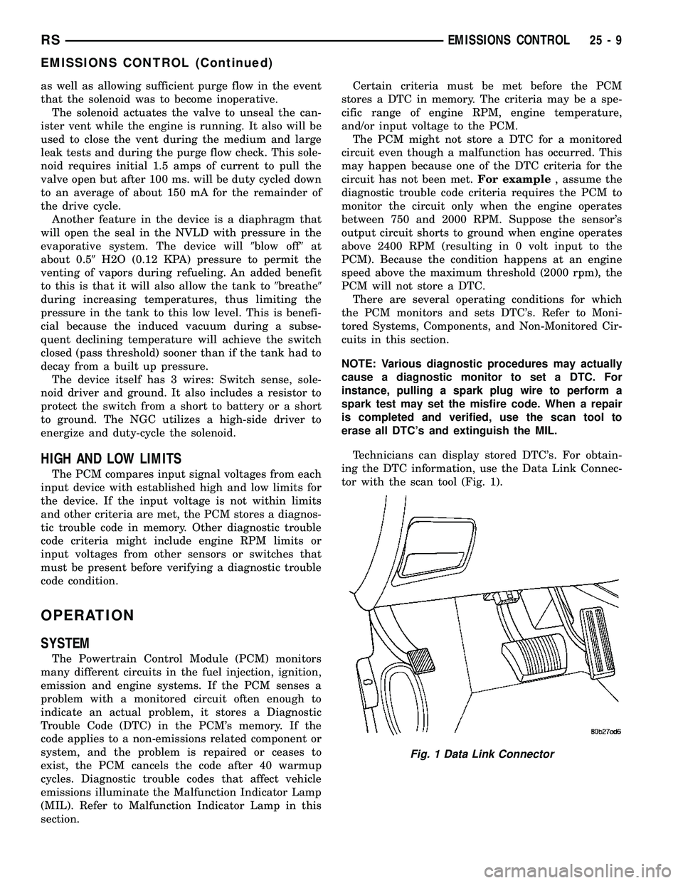
Technicians can display stored DTC's. For obtain-
ing the DTC information, use the Data Link Connec-
tor with the scan tool (Fig. 1).
Fig. 1 Data Link Connector
RSEMISSIONS CONTROL25-9
EMISSIONS CONTROL (Continued)
Page 2283 of 2339
DRB IIITSTATE DISPLAY TEST MODE
OPERATION
The switch inputs to the Powertrain Control Mod-
ule (PCM) have two recognized states; HIGH and
LOW. For this reason, the PCM cannot recognize the
difference between a selected switch position versusan open circuit, a short circuit, or a defective switch.
If the State Display screen shows the change from
HIGH to LOW or LOW to HIGH, assume the entire
switch circuit to the PCM functions properly. From
the state display screen, access either State Display
Inputs and Outputs or State Display Sensors.
25 - 10 EMISSIONS CONTROLRS
EMISSIONS CONTROL (Continued)
Page 2299 of 2339
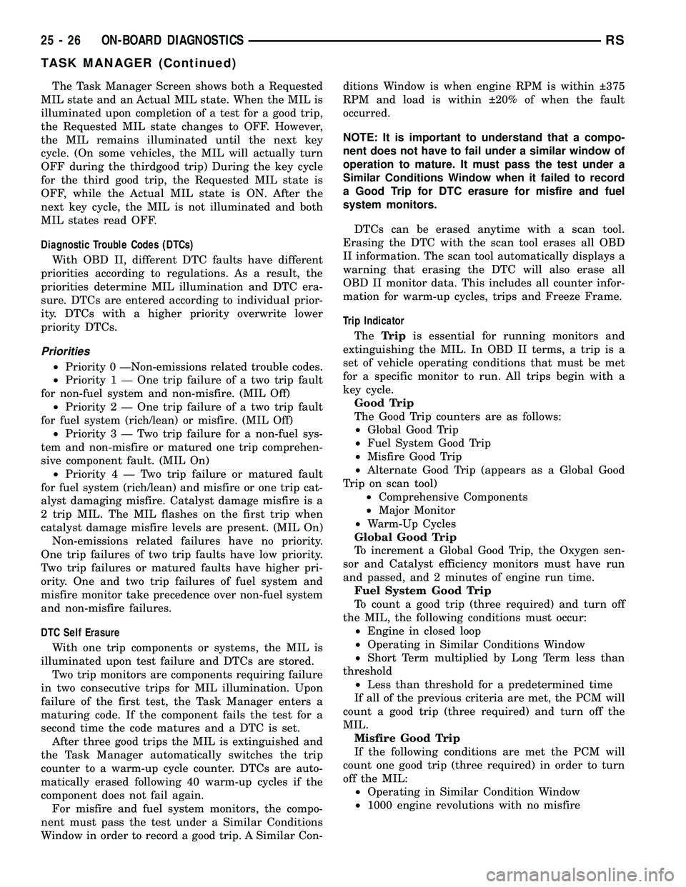
The Task Manager Screen shows both a Requested
MIL state and an Actual MIL state. When the MIL is
illuminated upon completion of a test for a good trip,
the Requested MIL state changes to OFF. However,
the MIL remains illuminated until the next key
cycle. (On some vehicles, the MIL will actually turn
OFF during the thirdgood trip) During the key cycle
for the third good trip, the Requested MIL state is
OFF, while the Actual MIL state is ON. After the
next key cycle, the MIL is not illuminated and both
MIL states read OFF.
Diagnostic Trouble Codes (DTCs)
With OBD II, different DTC faults have different
priorities according to regulations. As a result, the
priorities determine MIL illumination and DTC era-
sure. DTCs are entered according to individual prior-
ity. DTCs with a higher priority overwrite lower
priority DTCs.
Priorities
²Priority 0 ÐNon-emissions related trouble codes.
²Priority 1 Ð One trip failure of a two trip fault
for non-fuel system and non-misfire. (MIL Off)
²Priority 2 Ð One trip failure of a two trip fault
for fuel system (rich/lean) or misfire. (MIL Off)
²Priority3ÐTwotrip failure for a non-fuel sys-
tem and non-misfire or matured one trip comprehen-
sive component fault. (MIL On)
²Priority4ÐTwotrip failure or matured fault
for fuel system (rich/lean) and misfire or one trip cat-
alyst damaging misfire. Catalyst damage misfire is a
2 trip MIL. The MIL flashes on the first trip when
catalyst damage misfire levels are present. (MIL On)
Non-emissions related failures have no priority.
One trip failures of two trip faults have low priority.
Two trip failures or matured faults have higher pri-
ority. One and two trip failures of fuel system and
misfire monitor take precedence over non-fuel system
and non-misfire failures.
DTC Self Erasure
With one trip components or systems, the MIL is
illuminated upon test failure and DTCs are stored.
Two trip monitors are components requiring failure
in two consecutive trips for MIL illumination. Upon
failure of the first test, the Task Manager enters a
maturing code. If the component fails the test for a
second time the code matures and a DTC is set.
After three good trips the MIL is extinguished and
the Task Manager automatically switches the trip
counter to a warm-up cycle counter. DTCs are auto-
matically erased following 40 warm-up cycles if the
component does not fail again.
For misfire and fuel system monitors, the compo-
nent must pass the test under a Similar Conditions
Window in order to record a good trip. A Similar Con-ditions Window is when engine RPM is within 375
RPM and load is within 20% of when the fault
occurred.
NOTE: It is important to understand that a compo-
nent does not have to fail under a similar window of
operation to mature. It must pass the test under a
Similar Conditions Window when it failed to record
a Good Trip for DTC erasure for misfire and fuel
system monitors.
DTCs can be erased anytime with a scan tool.
Erasing the DTC with the scan tool erases all OBD
II information. The scan tool automatically displays a
warning that erasing the DTC will also erase all
OBD II monitor data. This includes all counter infor-
mation for warm-up cycles, trips and Freeze Frame.
Trip Indicator
TheTripis essential for running monitors and
extinguishing the MIL. In OBD II terms, a trip is a
set of vehicle operating conditions that must be met
for a specific monitor to run. All trips begin with a
key cycle.
Good Trip
The Good Trip counters are as follows:
²Global Good Trip
²Fuel System Good Trip
²Misfire Good Trip
²Alternate Good Trip (appears as a Global Good
Trip on scan tool)
²Comprehensive Components
²Major Monitor
²Warm-Up Cycles
Global Good Trip
To increment a Global Good Trip, the Oxygen sen-
sor and Catalyst efficiency monitors must have run
and passed, and 2 minutes of engine run time.
Fuel System Good Trip
To count a good trip (three required) and turn off
the MIL, the following conditions must occur:
²Engine in closed loop
²Operating in Similar Conditions Window
²Short Term multiplied by Long Term less than
threshold
²Less than threshold for a predetermined time
If all of the previous criteria are met, the PCM will
count a good trip (three required) and turn off the
MIL.
Misfire Good Trip
If the following conditions are met the PCM will
count one good trip (three required) in order to turn
off the MIL:
²Operating in Similar Condition Window
²1000 engine revolutions with no misfire
25 - 26 ON-BOARD DIAGNOSTICSRS
TASK MANAGER (Continued)
Page 2300 of 2339
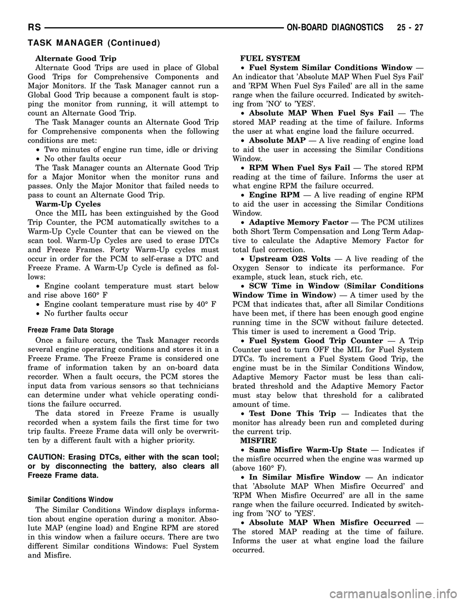
Alternate Good Trip
Alternate Good Trips are used in place of Global
Good Trips for Comprehensive Components and
Major Monitors. If the Task Manager cannot run a
Global Good Trip because a component fault is stop-
ping the monitor from running, it will attempt to
count an Alternate Good Trip.
The Task Manager counts an Alternate Good Trip
for Comprehensive components when the following
conditions are met:
²Two minutes of engine run time, idle or driving
²No other faults occur
The Task Manager counts an Alternate Good Trip
for a Major Monitor when the monitor runs and
passes. Only the Major Monitor that failed needs to
pass to count an Alternate Good Trip.
Warm-Up Cycles
Once the MIL has been extinguished by the Good
Trip Counter, the PCM automatically switches to a
Warm-Up Cycle Counter that can be viewed on the
scan tool. Warm-Up Cycles are used to erase DTCs
and Freeze Frames. Forty Warm-Up cycles must
occur in order for the PCM to self-erase a DTC and
Freeze Frame. A Warm-Up Cycle is defined as fol-
lows:
²Engine coolant temperature must start below
and rise above 160É F
²Engine coolant temperature must rise by 40É F
²No further faults occur
Freeze Frame Data Storage
Once a failure occurs, the Task Manager records
several engine operating conditions and stores it in a
Freeze Frame. The Freeze Frame is considered one
frame of information taken by an on-board data
recorder. When a fault occurs, the PCM stores the
input data from various sensors so that technicians
can determine under what vehicle operating condi-
tions the failure occurred.
The data stored in Freeze Frame is usually
recorded when a system fails the first time for two
trip faults. Freeze Frame data will only be overwrit-
ten by a different fault with a higher priority.
CAUTION: Erasing DTCs, either with the scan tool;
or by disconnecting the battery, also clears all
Freeze Frame data.
Similar Conditions Window
The Similar Conditions Window displays informa-
tion about engine operation during a monitor. Abso-
lute MAP (engine load) and Engine RPM are stored
in this window when a failure occurs. There are two
different Similar conditions Windows: Fuel System
and Misfire.FUEL SYSTEM
²Fuel System Similar Conditions WindowÐ
An indicator that 'Absolute MAP When Fuel Sys Fail'
and 'RPM When Fuel Sys Failed' are all in the same
range when the failure occurred. Indicated by switch-
ing from 'NO' to 'YES'.
²Absolute MAP When Fuel Sys FailÐ The
stored MAP reading at the time of failure. Informs
the user at what engine load the failure occurred.
²Absolute MAPÐ A live reading of engine load
to aid the user in accessing the Similar Conditions
Window.
²RPM When Fuel Sys FailÐ The stored RPM
reading at the time of failure. Informs the user at
what engine RPM the failure occurred.
²Engine RPMÐ A live reading of engine RPM
to aid the user in accessing the Similar Conditions
Window.
²Adaptive Memory FactorÐ The PCM utilizes
both Short Term Compensation and Long Term Adap-
tive to calculate the Adaptive Memory Factor for
total fuel correction.
²Upstream O2S VoltsÐ A live reading of the
Oxygen Sensor to indicate its performance. For
example, stuck lean, stuck rich, etc.
²SCW Time in Window (Similar Conditions
Window Time in Window)Ð A timer used by the
PCM that indicates that, after all Similar Conditions
have been met, if there has been enough good engine
running time in the SCW without failure detected.
This timer is used to increment a Good Trip.
²Fuel System Good Trip CounterÐATrip
Counter used to turn OFF the MIL for Fuel System
DTCs. To increment a Fuel System Good Trip, the
engine must be in the Similar Conditions Window,
Adaptive Memory Factor must be less than cali-
brated threshold and the Adaptive Memory Factor
must stay below that threshold for a calibrated
amount of time.
²Test Done This TripÐ Indicates that the
monitor has already been run and completed during
the current trip.
MISFIRE
²Same Misfire Warm-Up StateÐ Indicates if
the misfire occurred when the engine was warmed up
(above 160É F).
²In Similar Misfire WindowÐ An indicator
that 'Absolute MAP When Misfire Occurred' and
'RPM When Misfire Occurred' are all in the same
range when the failure occurred. Indicated by switch-
ing from 'NO' to 'YES'.
²Absolute MAP When Misfire OccurredÐ
The stored MAP reading at the time of failure.
Informs the user at what engine load the failure
occurred.
RSON-BOARD DIAGNOSTICS25-27
TASK MANAGER (Continued)
Page 2303 of 2339
AJAR SWITCH - EXPORT -INSTALLATION, HOOD .................8Q-3
AJAR SWITCH - EXPORT - REMOVAL, HOOD .............................. 8Q-3
ALIGNMENT - DESCRIPTION, WHEEL ......2-47
ALIGNMENT - EXPORT - STANDARD PROCEDURE, FRONT FOG LAMP UNIT .....8L-9
ALIGNMENT - EXPORT - STANDARD PROCEDURE, HEADLAMP UNIT .........8L-15
ALIGNMENT - STANDARD PROCEDURE, FRONT FOG LAMP UNIT ................8L-9
ALIGNMENT - STANDARD PROCEDURE, FRONT WIPER ARM ................... 8R-9
ALIGNMENT - STANDARD PROCEDURE, HEADLAMP UNIT ..................... 8L-14
ALIGNMENT - STANDARD PROCEDURE, WHEEL ............................. 2-52
ALIGNMENT, SPECIFICATIONS - WHEEL ....2-56
AMBIENT TEMP SENSOR - DESCRIPTION . 8M-12
AMBIENT TEMP SENSOR - OPERATION . . 8M-12
AMBIENT TEMPERATURE SENSOR CIRCUIT, DIAGNOSIS AND TESTING .....8M-12
AMBIENT TEMPERATURE SENSOR, DIAGNOSIS AND TESTING .............8M-12
AMPLIFIER - INSTALLATION .............8A-7
AMPLIFIER - REMOVAL ................8A-7
AN AIRBAG DEPLOYMENT - STANDARD PROCEDURE, SERVICE AFTER ...........8O-7
ANCHOR - DESCRIPTION, CHILD RESTRAINT .......................... 8O-9
ANCHOR - OPERATION, CHILD RESTRAINT .......................... 8O-10
ANTENNA - EXPORT - DESCRIPTION, QUARTER GLASS INTEGRAL ............8A-13
ANTENNA - EXPORT - OPERATION, QUARTER GLASS INTEGRAL ............8A-13
ANTENNA - NAVIGATION RADIO - INSTALLATION ....................... 8A-11
ANTENNA - NAVIGATION RADIO - REMOVAL .......................... 8A-11
ANTENNA BODY AND CABLE - DESCRIPTION ........................ 8A-7
ANTENNA BODY AND CABLE - OPERATION .......................... 8A-7
ANTENNA BODY AND CABLE, DIAGNOSIS AND TESTING ..............8A-8
ANTENNA CABLE - INSTALLATION, INSTRUMENT PANEL .................8A-12
ANTENNA CABLE - REMOVAL, INSTRUMENT PANEL .................8A-12
ANTENNA, EXPORT - QUARTER GLASS INTEGRAL .......................... 8A-13
ANTENNA MODULE - EXPORT - DESCRIPTION ....................... 8A-10
ANTENNA MODULE - EXPORT - OPERATION ......................... 8A-10
ANTENNA MODULE, EXPORT ...........8A-10
ANTILOCK BRAKE - DESCRIPTION, CONTROLLER ........................ 8E-4
ANTILOCK BRAKE - INSTALLATION, CONTROLLER ........................ 8E-6
ANTILOCK BRAKE - OPERATION, CONTROLLER ........................ 8E-5
ANTILOCK BRAKE - REMOVAL, CONTROLLER ........................ 8E-5
ANTILOCK BRAKE SYSTEM - DESCRIPTION ........................ 5-87
ANTILOCK BRAKE SYSTEM - OPERATION . . 5-88
ANTILOCK BRAKE SYSTEM BLEEDING - STANDARD PROCEDURE ................5-90
ANTILOCK BRAKE SYSTEM (EXPORT) - DESCRIPTION ........................ 5-87
A-PILLAR LOWER EXTENSION TRIM - INSTALLATION ....................... 23-79
A-PILLAR LOWER EXTENSION TRIM - REMOVAL .......................... 23-79
A-PILLAR TRIM - INSTALLATION ........23-79
A-PILLAR TRIM - REMOVAL ............23-79
A-PILLAR-HEADER, OR B-PILLAR - INSTALLATION ....................... 23-17
A-PILLAR-HEADER, OR B-PILLAR - REMOVAL .......................... 23-17
APPLIQUE - INSTALLATION .............23-14
APPLIQUE - REMOVAL ................23-14
ARM - DESCRIPTION, LOWER CONTROL . . . 2-12
ARM - INSPECTION, LOWER CONTROL ....2-14
ARM - INSTALLATION, LOWER CONTROL . . 2-15
ARM - INSTALLATION, REAR WIPER .....8R-10 ARM - OPERATION, LOWER CONTROL
.....2-12
ARM - REMOVAL, LOWER CONTROL ......2-12
ARM - REMOVAL, REAR WIPER .........8R-10
ARM ALIGNMENT - STANDARD PROCEDURE, FRONT WIPER ............8R-9
ARM (REAR BUSHING - HYDRO) - ASSEMBLY, LOWER CONTROL ...........2-15
ARM (REAR BUSHING - HYDRO) - DISASSEMBLY, LOWER CONTROL ........2-13
ARM (REAR BUSHING - STANDARD) - ASSEMBLY, LOWER CONTROL ...........2-14
ARM (REAR BUSHING - STANDARD) - DISASSEMBLY, LOWER CONTROL ........2-13
ARMREST - INSTALLATION ............23-108
ARMREST - REMOVAL ...............23-108
ARMREST - SECOND ROW - FOLD-IN- FLOOR - INSTALLATION ..............23-130
ARMREST - SECOND ROW - FOLD-IN- FLOOR - REMOVAL .................. 23-130
ARMREST ROTATING ASSEMBLY - SECOND ROW - FOLD-IN-FLOOR -
INSTALLATION ...................... 23-130
ARMREST ROTATING ASSEMBLY - SECOND ROW - FOLD-IN-FLOOR -
REMOVAL ......................... 23-130
ARMS - DESCRIPTION, ROCKER ........9-112
ARMS - INSPECTION, ROCKER ...........9-35
ARMS - INSTALLATION, FRONT WIPER ....8R-9
ARMS - INSTALLATION, ROCKER .........9-35
ARMS - OPERATION, ROCKER ..........9-112
ARMS - REMOVAL, FRONT WIPER .........8R-9
ARMS - REMOVAL, ROCKER .............9-35
ARMS AND SHAFT - ASSEMBLY, ROCKER ............................ 9-113
ARMS AND SHAFT - DISASSEMBLY, ROCKER ............................ 9-113
ARMS AND SHAFT - INSTALLATION, ROCKER ............................ 9-113
ARMS AND SHAFT - REMOVAL, ROCKER . . 9-112
ASSIST DISPLAY - DESCRIPTION, PARK . . . 8B-3
ASSIST DISPLAY - INSTALLATION, PARK . . . 8B-4
ASSIST DISPLAY - OPERATION, PARK .....8B-3
ASSIST DISPLAY - REMOVAL, PARK ......8B-4
ASSIST HANDLE - INSTALLATION ........23-79
ASSIST HANDLE - REMOVAL ...........23-79
ASSIST MODULE - DESCRIPTION, PARK . . . 8B-4
ASSIST MODULE - INSTALLATION, PARK . . 8B-6
ASSIST MODULE - OPERATION, PARK .....8B-5
ASSIST MODULE - REMOVAL, PARK ......8B-5
ASSIST SENSOR - DESCRIPTION, PARK . . . 8B-6
ASSIST SENSOR - INSTALLATION, PARK . . . 8B-6
ASSIST SENSOR - OPERATION, PARK .....8B-6
ASSIST SENSOR - REMOVAL, PARK ......8B-6
ASSIST STRAP - INSTALLATION, FRONT SEAT BACK ........................ 23-112
ASSIST STRAP - REMOVAL, FRONT SEAT BACK ........................ 23-112
ATTACHED - INSTALLATION, EXTERIOR NAME PLATES - ADHESIVE .............23-51
ATTACHED - INSTALLATION, EXTERIOR NAME PLATES - TAPE .................23-51
ATTACHED - REMOVAL, EXTERIOR NAME PLATES - ADHESIVE .................. 23-51
ATTACHED - REMOVAL, EXTERIOR NAME PLATES - TAPE ...................... 23-51
AUDIO/VIDEO - DESCRIPTION ...........8A-1
AUDIO/VIDEO, DIAGNOSIS AND TESTING . . 8A-2
AUTO SHUT DOWN RELAY - DESCRIPTION ......................... 8I-3
AUTO SHUT DOWN RELAY - OPERATION . . . 8I-3
AUTOMATIC ADJUSTER - DIAGNOSIS AND TESTING, DRUM BRAKE ............5-14
AUTOMATIC ADJUSTER TENSION RELEASE - STANDARD PROCEDURE,
PARKING BRAKE ...................... 5-63
AUTOMATIC ADJUSTER TENSION RESET - STANDARD PROCEDURE, PARKING
BRAKE .............................. 5-64
AUTOMATIC DAY / NIGHT MIRROR - DESCRIPTION ....................... 8N-28
AUTOMATIC DAY / NIGHT MIRROR - OPERATION ......................... 8N-28
AUTOMATIC DAY / NIGHT MIRROR, DIAGNOSIS AND TESTING .............8N-28
AUTOMATIC TEMPERATURE CONTROL, DESCRIPTION ........................ 24-3
AUTOMATIC TEMPERATURE CONTROL, OPERATION .......................... 24-5AUTOMATIC TEMPERATURE CONTROL
SYSTEM, OPERATION ................24-114
AUTOMATIC TRANSAXLE - DESCRIPTION, 40TE ................... 21-2
AUTOMATIC TRANSAXLE - DESCRIPTION, 41TE .................21-147
AUTOMATIC TRANSAXLE - OPERATION, 40TE ............................... 21-4
AUTOMATIC TRANSAXLE - OPERATION, 41TE ............................. 21-149
AUTOMATIC TRANSAXLE, SPECIAL TOOLS - 41TE ...................... 21-213
AUTOMATIC/MANUAL TRANSAXLE FLUID - DESCRIPTION ........................0-4
AWD - INSTALLATION ..................2-45
AWD - INSTALLATION, REAR WHEEL SPEED SENSOR ....................... 5-92
AWD - INSTALLATION, SPRING ..........2-39
AWD - REMOVAL ..................... 2-44
AWD - REMOVAL, REAR WHEEL SPEED SENSOR ............................ 5-92
AWD - REMOVAL, SPRING ..............2-38
AWD, HEAVY DUTY, CARGO - INSTALLATION ........................ 2-36
AWD, HEAVY DUTY, CARGO - REMOVAL . . . 2-36
AWD POWER TRANSFER UNIT FLUID - DESCRIPTION .........................0-6
AWD REAR DRIVELINE MODULE FLUIDS - DESCRIPTION ........................0-6
B OR C-PILLAR - INSTALLATION, SEAT BELT HEIGHT ADJUSTER ..............8O-38
B OR C-PILLAR - REMOVAL, SEAT BELT HEIGHT ADJUSTER ................... 8O-38
BACK - INSTALLATION, BENCH SEAT ....23-147
BACK - INSTALLATION, FRONT SEAT ....23-111
BACK - QUAD BUCKET - INSTALLATION, BUCKET SEAT ...................... 23-141
BACK - QUAD BUCKET - REMOVAL, BUCKET SEAT ...................... 23-140
BACK - REMOVAL, BENCH SEAT ........23-147
BACK - REMOVAL, FRONT SEAT ........23-111
BACK ASSIST STRAP - INSTALLATION, FRONT SEAT ....................... 23-112
BACK ASSIST STRAP - REMOVAL, FRONT SEAT ....................... 23-112
BACK COVER - INSTALLATION, BENCH SEAT ............................. 23-148
BACK COVER - INSTALLATION, FRONT SEAT ............................. 23-116
BACK COVER - REMOVAL, BENCH SEAT . . 23-148
BACK COVER - REMOVAL, FRONT SEAT . . 23-113
BACK COVER/FOAM - SECOND ROW - FOLD-IN-FLOOR - INSTALLATION, SEAT . . 23-133
BACK COVER/FOAM - SECOND ROW - FOLD-IN-FLOOR - REMOVAL, SEAT ......23-133
BACK COVER/FOAM - THIRD ROW - FOLD-IN-FLOOR - INSTALLATION, SEAT . . 23-156
BACK COVER/FOAM - THIRD ROW - FOLD-IN-FLOOR - REMOVAL, SEAT ......23-155
BACK FRAME - SECOND ROW - FOLD-IN-FLOOR - INSTALLATION, SEAT . . 23-134
BACK FRAME - SECOND ROW - FOLD-IN-FLOOR - REMOVAL, SEAT ......23-134
BACK FRAME - THIRD ROW - FOLD-IN-FLOOR - INSTALLATION, SEAT . . 23-157
BACK FRAME - THIRD ROW - FOLD-IN-FLOOR - REMOVAL, SEAT ......23-156
BACK HINGE - REMOVAL, BENCH SEAT . . 23-146
BACK HINGE COVERS - QUAD BUCKET, 50/50 SPLIT, BENCH - INSTALLATION,
SEAT ............................. 23-146
BACK HINGE COVERS - QUAD BUCKET, 50/50 SPLIT, BENCH - REMOVAL, SEAT . . 23-146
BACK PANEL - INSTALLATION, BENCH SEAT ............................. 23-144
BACK PANEL - INSTALLATION, FRONT SEAT ............................. 23-113
BACK PANEL - REMOVAL, BENCH SEAT . . 23-143
BACK PANEL - REMOVAL, FRONT SEAT . . 23-112
BACK PANEL - SECOND ROW -FOLD-IN-FLOOR - INSTALLATION,
SEAT ............................. 23-134
BACK PANEL - SECOND ROW -FOLD-IN-FLOOR - REMOVAL, SEAT .....23-134
BACK PANEL - THIRD ROW -FOLD-IN- FLOOR - INSTALLATION, SEAT .........23-158
BACK PANEL - THIRD ROW -FOLD-IN- FLOOR - REMOVAL, SEAT .............23-158
2 INDEXRS
Description Group-Page Description Group-Page Description Group-Page
Page 2311 of 2339
DEFOGGER RELAY - DESCRIPTION,REAR WINDOW ....................... 8G-3
DEFOGGER RELAY - INSTALLATION, REAR WINDOW ....................... 8G-4
DEFOGGER RELAY - OPERATION, REAR WINDOW ............................ 8G-3
DEFOGGER RELAY - REMOVAL, REAR WINDOW ............................ 8G-4
DEFOGGER SWITCH - DESCRIPTION, REAR WINDOW ....................... 8G-4
DEFOGGER SWITCH - OPERATION, REAR WINDOW ............................ 8G-4
DEFROSTER DUCT - INSTALLATION ......24-50
DEFROSTER DUCT - REMOVAL ..........24-49
DEMAGNETIZING, STANDARD PROCEDURE - COMPASS ...............8M-5
DEMISTER DUCTS - INSTALLATION, INSTRUMENT PANEL .................. 24-54
DEMISTER DUCTS - REMOVAL, INSTRUMENT PANEL .................. 24-54
DEMISTER OUTLETS, INSTALLATION - FRONT ............................. 24-45
DEMISTER OUTLETS, REMOVAL - FRONT . 24-44
DEPLOYMENT - STANDARD PROCEDURE, SERVICE AFTER AN
AIRBAG ............................. 8O-7
DETECTION ASSY - INSTALLATION, NATURAL VAC LEAK .................. 25-14
DETECTION ASSY - REMOVAL, NATURAL VAC LEAK .......................... 25-14
DETECTION PUMP - INSTALLATION, LEAK .............................. 25-15
DETECTION PUMP - REMOVAL, LEAK ......25-15
DEVICES - STANDARD PROCEDURE, ELECTROSTATIC DISCHARGE (ESD)
SENSITIVE ........................8W -01-8
DIAGNOSTIC SYSTEM, DIAGNOSIS AND TESTING - ON-BOARD .................8F-22
DIAGNOSTIC TROUBLE CODES - STANDARD PROCEDURE, OBTAINING .....8E-15
DIAGRAMS - 4XTE TRANSAXLE HYDRAULIC SCHEMATICS,
SCHEMATICS .................. 21-199,21-54
DIAGRAMS - DESCRIPTION, HOW TO USE WIRING ......................8W -01-1
DIAGRAMS - SPECIAL TOOLS, SCHEMATICS ........................ 21-68
DIESEL - DESCRIPTION ...............19-52
DIESEL - INSTALLATION ...............19-53
DIESEL - REMOVAL ................... 19-52
DIESEL ENGINE - DESCRIPTION, FUEL REQUIREMENTS .......................0-6
DIESEL ENGINES - DESCRIPTION, ENGINE OIL ...........................0-6
DIESEL ENGINES - EXPORT - DESCRIPTION ........................ 0-21
DIESEL ENGINES, INSTALLATION - 2.5L/2.8L ........................... 24-78
DIESEL ENGINES, REMOVAL - 2.5L/2.8L . . 24-77
DIFFERENTIAL BEARING PRELOAD - ADJUSTMENT ...................... 21-228
DIFFERENTIAL BEARING PRELOAD MEASUREMENT AND ADJUSTMENT,
ADJUSTMENTS ...................... 21-79
DIMENSIONS - FOLD-IN-FLOOR SEATS ONLY - SPECIFICATIONS, FRAME ........13-11
DIMENSIONS - SPECIFICATIONS, BODY OPENING .......................... 23-180
DIMENSIONS - SPECIFICATIONS, FRAME . . . 13-6
DIODE - INSTALLATION ............8W-01-14
DIODE - REMOVAL ................8W -01-14
DISABLED INDICATOR - DESCRIPTION, PASSENGER AIRBAG .................8O-33
DISABLED INDICATOR - INSTALLATION, PASSENGER AIRBAG .................8O-34
DISABLED INDICATOR - OPERATION, PASSENGER AIRBAG .................8O-33
DISABLED INDICATOR - REMOVAL, PASSENGER AIRBAG .................8O-34
DISASSEMBLY/ASSEMBLY - STANDARD PROCEDURE, TRANSMISSION COOLER
LINE QUICK CONNECT FITTING ...........7-38
DISC BRAKE CALIPER - INSTALLATION, REAR ............................... 5-30
DISC BRAKE CALIPER - REMOVAL, REAR ............................... 5-28
DISC BRAKE CALIPER ADAPTER - INSTALLATION, FRONT .................5-31DISC BRAKE CALIPER ADAPTER -
REMOVAL, FRONT ..................... 5-31
DISC BRAKE CALIPER (CONTINENTAL TEVES BRAKES) - INSTALLATION,
FRONT .............................. 5-27
DISC BRAKE CALIPER (CONTINENTAL TEVES BRAKES) - REMOVAL, FRONT ......5-24
DISC BRAKE CALIPER GUIDE PINS (TRW BRAKES) - INSTALLATION ...............5-32
DISC BRAKE CALIPER GUIDE PINS (TRW BRAKES) - REMOVAL .................. 5-31
DISC BRAKE CALIPER (TRW BRAKES) - INSTALLATION, FRONT .................5-27
DISC BRAKE CALIPER (TRW BRAKES) - REMOVAL, FRONT ..................... 5-24
DISC BRAKE SHOES - CLEANING .....5-16,5-18
DISC BRAKE SHOES - INSPECTION . . . 5-16,5-18
DISC BRAKE SHOES - INSTALLATION, REAR ............................... 5-19
DISC BRAKE SHOES - REMOVAL, REAR ....5-17
DISC BRAKE SHOES (CONTINENTAL TEVES BRAKES) - INSTALLATION,
FRONT .............................. 5-16
DISC BRAKE SHOES (CONTINENTAL TEVES BRAKES) - REMOVAL, FRONT ......5-15
DISC BRAKE SHOES (TRW BRAKES) - INSTALLATION, FRONT .................5-17
DISC BRAKE SHOES (TRW BRAKES) - REMOVAL, FRONT ..................... 5-15
DISC BRAKES (EXPORT) - DESCRIPTION . . . 5-13
DISC BRAKES (FRONT) - DESCRIPTION ....5-11
DISC BRAKES (FRONT) - OPERATION ......5-13
DISC BRAKES (REAR) - DESCRIPTION .....5-13
DISC BRAKES (REAR) - OPERATION ......5-14
DISCHARGE (ESD) SENSITIVE DEVICES - STANDARD PROCEDURE,
ELECTROSTATIC ...................8W -01-8
DISCHARGE LINE - INSTALLATION, A/C . . . 24-80
DISCHARGE LINE - REMOVAL, A/C .......24-79
DISPLAY - DESCRIPTION, PARK ASSIST . . . 8B-3
DISPLAY - INSTALLATION, PARK ASSIST . . . 8B-4
DISPLAY - OPERATION, PARK ASSIST .....8B-3
DISPLAY - REMOVAL, PARK ASSIST ......8B-4
DISPLAY TEST MODE, OPERATION - DRB III T STATE .......................... 25-10
DISSASEMBLY, REMOVAL ..............24-51
DISTRIBUTION DUCT - INSTALLATION ....24-57
DISTRIBUTION DUCT - REMOVAL ........24-57
DISTRIBUTION DUCTS - INSTALLATION, FLOOR ............................. 24-50
DISTRIBUTION DUCTS - REMOVAL, FLOOR ............................. 24-50
DISTRIBUTION SYSTEM - DESCRIPTION, POWER ..........................8W -97-1
DISTRIBUTION SYSTEM - OPERATION, POWER ..........................8W -97-1
DISTRIBUTION SYSTEMS, SPECIAL TOOLS - POWER ...................8W -97-1
DOES NOT FILL - DIAGNOSIS AND TESTING, VEHICLE ................... 25-17
DOME/CARGO LAMP - INSTALLATION ....8L-22
DOME/CARGO LAMP - REMOVAL ........8L-22
DOOR - INSTALLATION ................23-15
DOOR - INSTALLATION, FUEL FILL .......23-52
DOOR - INSTALLATION, SLIDING ........23-29
DOOR - REMOVAL .................... 23-15
DOOR - REMOVAL, FUEL FILL ..........23-52
DOOR - REMOVAL, SLIDING ............23-29
DOOR ACTUATOR - DESCRIPTION, BLEND ........................ 24-22,24-34
DOOR ACTUATOR - DESCRIPTION, MODE ............................. 24-29
DOOR ACTUATOR - DESCRIPTION, RECIRCULATION ..................... 24-31
DOOR ACTUATOR - INSTALLATION, BLEND ........................ 24-22,24-35
DOOR ACTUATOR - INSTALLATION, MODE ............................. 24-30
DOOR ACTUATOR - INSTALLATION, RECIRCULATION ..................... 24-32
DOOR ACTUATOR - OPERATION, BLEND . . 24-22,
24-35
DOOR ACTUATOR - OPERATION, MODE . . . 24-29
DOOR ACTUATOR - OPERATION, RECIRCULATION ..................... 24-31
DOOR ACTUATOR - REAR - DESCRIPTION, MODE .................24-39DOOR ACTUATOR - REAR -
INSTALLATION, MODE .................24-40
DOOR ACTUATOR - REAR - OPERATION, MODE ............................. 24-39
DOOR ACTUATOR - REAR - REMOVAL, MODE ............................. 24-39
DOOR ACTUATOR - REMOVAL, BLEND . . . 24-22, 24-35
DOOR ACTUATOR - REMOVAL, MODE ....24-29
DOOR ACTUATOR - REMOVAL, RECIRCULATION ..................... 24-32
DOOR ADJUSTMENT, STANDARD PROCEDURE - POWER SLIDING .........8N-49
DOOR ADJUSTMENTS, ADJUSTMENTS - SLIDING ............................ 23-30
DOOR BLOCKER LATCH - INSTALLATION, FUEL FILL .......................... 23-53
DOOR BLOCKER LATCH - REMOVAL, FUEL FILL .......................... 23-53
DOOR BLOCKER LATCH STRIKER - INSTALLATION, FUEL FILL .............23-53
DOOR BLOCKER LATCH STRIKER - REMOVAL, FUEL FILL .................23-53
DOOR BLOCKER LOCKOUT LINK - INSTALLATION, FUEL FILL .............23-54
DOOR BLOCKER LOCKOUT LINK - REMOVAL, FUEL FILL .................23-54
DOOR CONTROL MODULE - DESCRIPTION, SLIDING ...............8E-18
DOOR CONTROL MODULE - OPERATION, SLIDING ............................ 8E-18
DOOR CONTROL MODULE, DIAGNOSIS AND TESTING - SLIDING ...............8E-18
DOOR CYLINDER LOCK SWITCH - EXPORT - DESCRIPTION ...............8N-22
DOOR CYLINDER LOCK SWITCH - EXPORT - OPERATION ................8N-22
DOOR CYLINDER LOCK SWITCH, EXPORT ............................ 8N-22
DOOR GLASS - INSTALLATION ..........23-17
DOOR GLASS - INSTALLATION, SLIDING . 23-163
DOOR GLASS - REMOVAL .............23-16
DOOR GLASS - REMOVAL, SLIDING .....23-163
DOOR GLASS RUN WEATHERSTRIP - INSTALLATION, FRONT ...............23-166
DOOR GLASS RUN WEATHERSTRIP - REMOVAL, FRONT ................... 23-166
DOOR INNER BELT MOLDING - INSTALLATION, FRONT ...............23-168
DOOR INNER BELT MOLDING - REMOVAL, FRONT ................... 23-168
DOOR LEARN CYCLE, STANDARD PROCEDURE - POWER SLIDING .........8N-48
DOOR LOCK MOTOR - INSTALLATION, SLIDING ........................... 8N-25
DOOR LOCK MOTOR - REMOVAL, SLIDING ........................... 8N-25
DOOR LOCK MOTOR, DIAGNOSIS AND TESTING ........................... 8N-23
DOOR LOCK SWITCH, DIAGNOSIS AND TESTING ........................... 8N-23
DOOR MOTOR - DESCRIPTION, SLIDING . . 8N-51
DOOR MOTOR - INSTALLATION, SLIDING . 8N-51
DOOR MOTOR - OPERATION, SLIDING . . . 8N-51
DOOR MOTOR - REMOVAL, SLIDING .....8N-51
DOOR OUTER BELT MOLDING - INSTALLATION, FRONT ...............23-167
DOOR OUTER BELT MOLDING - REMOVAL, FRONT ................... 23-167
DOOR SILL PLATE - INSTALLATION, SLIDING ............................ 23-99
DOOR SILL PLATE - REMOVAL, SLIDING . . 23-98
DOOR SILL TRIM PLATE - INSTALLATION ....................... 23-89
DOOR SILL TRIM PLATE - REMOVAL .....23-89
DOOR STOP BUMPER BEZEL - INSTALLATION, SLIDING ...............23-25
DOOR STOP BUMPER BEZEL - REMOVAL, SLIDING .................. 23-25
DOOR SYSTEM - DESCRIPTION, POWER SLIDING ........................... 8N-40
DOOR SYSTEM - OPERATION, POWER SLIDING ........................... 8N-41
DOOR SYSTEM, DIAGNOSIS AND TESTING - POWER SLIDING ............8N-42
DOOR WEATHERSTRIP - INSTALLATION, FRONT ............................ 23-168
10 INDEXRS
Description Group-Page Description Group-Page Description Group-Page