2005 CHRYSLER CARAVAN key
[x] Cancel search: keyPage 816 of 2339

8W-45 BODY CONTROL MODULE
Component Page
A/C-Heater Control............... 8W-45-16, 19
Auto Temp Control............... 8W-45-16, 19
Body Control Module . . . 8W-45-2, 3, 4, 5, 6, 7, 8, 9,
10, 11, 12, 13, 15, 16, 17, 18, 19, 20
Clockspring........................ 8W-45-17
Controller Antilock Brake............. 8W-45-13
Driver Door Courtesy Lamp........... 8W-45-15
Driver Door Lock Switch........... 8W-45-12, 15
Driver Heated Seat Module........... 8W-45-11
Floor Console Lamp................. 8W-45-13
Front Control Module................. 8W-45-3
Front Reading Lamps/Switch....... 8W-45-13, 15
Fuel Pump Module.................. 8W-45-15
Fuse 14............................ 8W-45-3
Fuse 19............................ 8W-45-2
Fuse 24............................ 8W-45-2
G301............................ 8W-45-2, 8
Headlamp Switch............. 8W-45-11, 16, 20
Hood Ajar Switch................... 8W-45-12
Ignition Switch...................... 8W-45-3
Instrument Cluster.......... 8W-45-2, 16, 18, 19
Instrument Panel Switch
Bank.................. 8W-45-10, 11, 17, 19
Integrated Power Module..... 8W-45-2, 3, 5, 6, 13
Left B-Pillar Switch.................. 8W-45-9
Left Cylinder Lock Switch............ 8W-45-10
Left Front Door Ajar Switch............ 8W-45-9
Left Front Door Lock Motor/Ajar
Switch........................ 8W-45-7, 9
Left Liftgate Flood Lamp............. 8W-45-12
Left Mid Reading Lamp............ 8W-45-9, 14
Left Power Mirror................... 8W-45-20
Left Rear Lamp Assembly........... 8W-45-5, 6
Left Rear Reading Lamp........... 8W-45-9, 14
Left Remote Radio Switch............ 8W-45-17
Left Repeater Lamp................. 8W-45-20
Left Sliding Door Control Module..... 8W-45-8, 10
Left Sliding Door Lock Motor........... 8W-45-7
Left Sliding Door Lock Motor/Ajar
Switch........................ 8W-45-7, 8
Left Visor/Vanity Lamp.............. 8W-45-13Component Page
License Lamp....................... 8W-45-8
Liftgate Ajar Switch................. 8W-45-12
Liftgate Cinch/Release Motor.......... 8W-45-12
Memory Set Switch.................. 8W-45-4
Message Center.................... 8W-45-18
Multi-Function Switch............... 8W-45-16
Overhead Console................. 8W-45-4, 11
Passenger Door Courtesy Lamp........ 8W-45-15
Passenger Door Lock Switch........ 8W-45-12, 15
Passenger Folding Mirror Relay........ 8W-45-20
Passenger Heated Seat Module........ 8W-45-11
Power Folding Mirror Switch.......... 8W-45-20
Power Liftgate Module............. 8W-45-8, 12
Radio............................ 8W-45-17
Rear Auto Temp Control Switch..... 8W-45-10, 19
Rear Blower Rear Control Switch....... 8W-45-10
Rear Dome Lamp.................... 8W-45-9
Rear View Mirror................... 8W-45-11
Rear Wiper Motor.................... 8W-45-8
Right B-Pillar Switch................. 8W-45-9
Right Cylinder Lock Switch........... 8W-45-10
Right Front Door Ajar Switch........... 8W-45-9
Right Front Door Lock Motor/Ajar
Switch........................ 8W-45-7, 9
Right Liftgate Flood Lamp............ 8W-45-12
Right Mid Reading Lamp........... 8W-45-9, 14
Right Power Mirror................. 8W-45-20
Right Rear Lamp Assembly.......... 8W-45-5, 6
Right Rear Reading Lamp.......... 8W-45-9, 14
Right Remote Radio Switch........... 8W-45-17
Right Repeater Lamp................ 8W-45-20
Right Sliding Door Control Module.... 8W-45-8, 10
Right Sliding Door Lock Motor.......... 8W-45-7
Right Sliding Door Lock Motor/Ajar
Switch........................ 8W-45-7, 8
Right Visor/Vanity Lamp............. 8W-45-13
Sentry Key Remote Entry Module....... 8W-45-3
Thatcham Alarm Module............. 8W-45-10
Traction Control Switch.............. 8W-45-17
Trailer Tow Connector................ 8W-45-5
RS8W-45 BODY CONTROL MODULE8W-45-1
Page 904 of 2339

8W-56 CONVENIENCE SYSTEMS
Component Page
Adjustable Pedals Motor............. 8W-56-2, 3
Adjustable Pedals Relay............... 8W-56-2
Adjustable Pedals Sensor.............. 8W-56-3
Adjustable Pedals Switch.............. 8W-56-2
Driver Heated Seat Module............ 8W-56-3
Front Control Module............... 8W-56-2, 4
Fuse 14............................ 8W-56-2
Fuse 18............................ 8W-56-2
Fuse 22............................ 8W-56-3
G200.............................. 8W-56-2
G300.............................. 8W-56-3
G302.............................. 8W-56-4
Ignition Switch...................... 8W-56-4Component Page
Integrated Power Module.......... 8W-56-2, 3, 4
Left Sliding Door Control Module........ 8W-56-2
Memory Seat/Mirror/Adjustable Pedals
Module........................ 8W-56-2, 3
Park Assist Display.................. 8W-56-4
Park Assist Module............... 8W-56-4, 5, 6
Park Assist Sensor No. 1............ 8W-56-5, 6
Park Assist Sensor No. 2............ 8W-56-5, 6
Park Assist Sensor No. 3............ 8W-56-5, 6
Park Assist Sensor No. 4............ 8W-56-5, 6
Power Seat Circuit Breaker............ 8W-56-3
Sentry Key Remote Entry Module....... 8W-56-4
RS8W-56 CONVENIENCE SYSTEMS8W-56-1
Page 918 of 2339

8W-61 POWER DOOR LOCKS
Component Page
Amplifier.......................... 8W-61-7
Body Control Module...... 8W-61-2, 3, 4, 5, 8, 11,
14, 15, 16, 17, 20
Driver Door Lock Switch............ 8W-61-2, 3
Front Control Module.............. 8W-61-6, 17
Fuse 14............................ 8W-61-5
Fuse 19..................... 8W-61-2, 3, 4, 15
Fuse 31............................ 8W-61-8
Fuse 32........................... 8W-61-17
G200.............................. 8W-61-5
G300................ 8W-61-2, 3, 4, 8, 9, 10, 15
G301.............. 8W-61-2, 3, 4, 11, 12, 13, 15
G302............................. 8W-61-17
G303....................... 8W-61-16, 19, 20
Integrated Power
Module........ 8W-61-2, 3, 4, 5, 6, 8, 11, 15, 17
Left B-Pillar Switch.................. 8W-61-8
Left Cinch/Release Motor.............. 8W-61-9
Left Front Door Lock Motor/Ajar Switch . . 8W-61-4
Left Full Open Switch................ 8W-61-9
Left Sliding Door Control
Module................ 8W-61-6, 8, 9, 10, 14
Left Sliding Door Latch
Sensing Switch................. 8W-61-8, 10
Left Sliding Door Lock Motor.......... 8W-61-14
Left Sliding Door Lock Motor/Ajar
Switch......................... 8W-61-15Component Page
Left Sliding Door Motor............... 8W-61-9
License Lamp................... 8W-61-19, 20
Liftgate Ajar Switch................. 8W-61-16
Liftgate Cinch/Release Motor.......... 8W-61-19
Liftgate Left Pinch Sensor............ 8W-61-19
Liftgate Right Pinch Sensor........... 8W-61-19
Memory Seat/Mirror/Adjustable Pedals
Module.......................... 8W-61-6
Overhead Console.................... 8W-61-7
Passenger Door Lock Switch......... 8W-61-2, 3
Power Liftgate Module...... 8W-61-17, 18, 19, 20
Power Liftgate Motor................ 8W-61-18
Right B-Pillar Switch................ 8W-61-11
Right Cinch/Release Motor............ 8W-61-12
Right Front Door Lock Motor/Ajar
Switch.......................... 8W-61-4
Right Full Open Switch.............. 8W-61-12
Right Sliding Door Control
Module............... 8W-61-7, 11, 12, 13, 14
Right Sliding Door Latch Sensing
Switch....................... 8W-61-11, 13
Right Sliding Door Lock Motor......... 8W-61-14
Right Sliding Door Lock Motor/Ajar
Switch......................... 8W-61-15
Right Sliding Door Motor............. 8W-61-12
Sentry Key Remote Entry Module....... 8W-61-5
RS8W-61 POWER DOOR LOCKS8W-61-1
Page 974 of 2339

Component Page
Rear Blower Front Control Switch (3 Zone
MTC)......................... 8W-80-124
Rear Blower Motor Power Module C1 (3 Zone
ATC) .......................... 8W-80-125
Rear Blower Motor Power Module C2 (3 Zone
ATC) .......................... 8W-80-125
Rear Blower Rear Control Switch C1 (3 Zone
MTC)......................... 8W-80-125
Rear Blower Rear Control Switch C2 (3 Zone
MTC)......................... 8W-80-125
Rear Dome Lamp (Except Luxury)..... 8W-80-126
Rear Intrusion Sensor (United
Kingdom)...................... 8W-80-126
Rear Mode Motor (3 Zone ATC)....... 8W-80-126
Rear Power Outlet................. 8W-80-126
Rear Temperature Motor (3 Zone ATC) . . 8W-80-127
Rear View Mirror C1 (Luxury)........ 8W-80-127
Rear View Mirror C2 (Hands Free)..... 8W-80-127
Rear Wiper Motor.................. 8W-80-128
Recirculation Door Actuator.......... 8W-80-128
Right B-Pillar Switch (Power Sliding
Door).......................... 8W-80-128
Right Cinch/Release Motor (Power Sliding
Door).......................... 8W-80-128
Right Curtain Airbag Squib.......... 8W-80-129
Right Cylinder Lock Switch (Export) . . . 8W-80-129
Right Door Speaker................ 8W-80-129
Right Fog Lamp................... 8W-80-129
Right Front Door Ajar Switch (Base) . . . 8W-80-130
Right Front Door Lock Motor/Ajar Switch (Except
Base).......................... 8W-80-130
Right Front Impact Sensor........... 8W-80-130
Right Front Park/Turn Signal Lamp.... 8W-80-130
Right Front Wheel Speed Sensor...... 8W-80-131
Right Full Open Switch (Power Sliding
Door).......................... 8W-80-131
Right Headlamp (Caravan/Voyager Except
Export)........................ 8W-80-131
Right Headlamp (Town And Country) . . . 8W-80-131
Right Headlamp Leveling Motor
(Export)....................... 8W-80-132
Right High Beam Lamp (Export)...... 8W-80-132
Right Instrument Panel Speaker...... 8W-80-132
Right Liftgate Flood Lamp........... 8W-80-132
Right Low Beam Lamp (Export)....... 8W-80-133
Right Mid Reading Lamp (Premium/
Luxury)........................ 8W-80-133
Right Park Lamp (Export)........... 8W-80-133
Right Power Mirror................ 8W-80-133
Right Rear Lamp Assembly.......... 8W-80-134
Right Rear Pillar Speaker (Highline
Audio)......................... 8W-80-134Component Page
Right Rear Reading Lamp (Luxury).... 8W-80-134
Right Rear Speaker................ 8W-80-134
Right Rear Vent Motor.............. 8W-80-135
Right Rear Wheel Speed Sensor....... 8W-80-135
Right Remote Radio Switch.......... 8W-80-135
Right Repeater Lamp (Export)........ 8W-80-135
Right Side Impact Sensor 1 (Export) . . . 8W-80-135
Right Side Impact Sensor 1 (Except
Export)........................ 8W-80-136
Right Side Impact Sensor 2.......... 8W-80-136
Right Side Impact Sensor 3.......... 8W-80-136
Right Sliding Door Control Module C1 (Power
Sliding Door)................... 8W-80-136
Right Sliding Door Control Module C2 (Power
Sliding Door)................... 8W-80-137
Right Sliding Door Latch Sensing Switch (Power
Sliding Door)................... 8W-80-137
Right Sliding Door Lock Motor (Power Sliding
Door).......................... 8W-80-137
Right Sliding Door Lock Motor/Ajar Switch (Manual
Sliding Door)................... 8W-80-138
Right Sliding Door Motor (Power Sliding
Door).......................... 8W-80-138
Right Speed Control Switch.......... 8W-80-138
Right Turn Signal Lamp (Export)...... 8W-80-138
Right Visor/Vanity Lamp (Except Base/
Export)........................ 8W-80-139
Sentry Key Remote Entry Module
(SKREEM)..................... 8W-80-139
Siren (United Kingdom)............. 8W-80-139
Speed Control Servo (Gas)........... 8W-80-139
Sunroof Module (Except Export)....... 8W-80-140
Sunroof Switch (Except Export)....... 8W-80-140
Thatcham Alarm Module (United
Kingdom)...................... 8W-80-140
Throttle Position Sensor (Gas)........ 8W-80-141
Traction Control Switch............. 8W-80-141
Trailer Tow Connector (Except Export) . . 8W-80-141
Transmission Control Module (Diesel) . . 8W-80-141
Transmission Control Relay (Diesel).... 8W-80-143
Transmission Range Sensor.......... 8W-80-143
Transmission Solenoid/Pressure Switch
Assembly...................... 8W-80-143
Vehicle Speed Sensor (MTX).......... 8W-80-144
Washer Fluid Level Switch........... 8W-80-144
Washer Pump Motor................ 8W-80-144
Water In Fuel Sensor (Diesel)......... 8W-80-144
Wiper Module..................... 8W-80-144
RS8W-80 CONNECTOR PIN-OUTS8W-80-5
Page 1108 of 2339

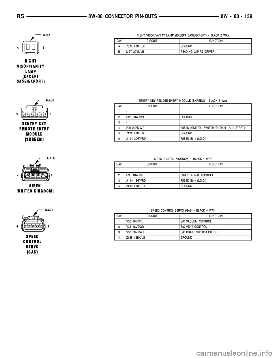
RIGHT VISOR/VANITY LAMP (EXCEPT BASE/EXPORT) - BLACK 2 WAY
CAV CIRCUIT FUNCTION
A Z327 20BK/OR GROUND
B M27 20YL/LB READING LAMPS DRIVER
SENTRY KEY REMOTE ENTRY MODULE (SKREEM) - BLACK 6 WAY
CAV CIRCUIT FUNCTION
1- -
2 D25 20WT/VT PCI BUS
3- -
4 F20 20PK/WT FUSED IGNITION SWITCH OUTPUT (RUN-START)
5 Z120 22BK/WT GROUND
6 A114 20GY/RD FUSED B(+) (I.O.D.)
SIREN (UNITED KINGDOM) - BLACK 4 WAY
CAV CIRCUIT FUNCTION
1- -
2 D96 18WT/LB SIREN SIGNAL CONTROL
3 A114 18GY/RD FUSED B(+) (I.O.D.)
4 Z109 18BK/GY GROUND
SPEED CONTROL SERVO (GAS) - BLACK 4 WAY
CAV CIRCUIT FUNCTION
1 V36 18VT/YL S/C VACUUM CONTROL
2 V35 18VT/OR S/C VENT CONTROL
3 V30 20VT/WT S/C BRAKE SWITCH OUTPUT
4 Z155 18BK/LG GROUND
RS8W-80 CONNECTOR PIN-OUTS8W - 80 - 139
Page 1125 of 2339

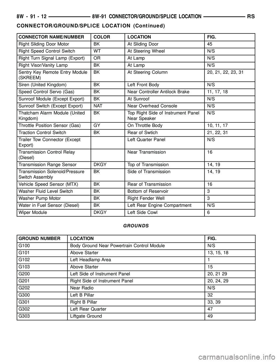
CONNECTOR NAME/NUMBER COLOR LOCATION FIG.
Right Sliding Door Motor BK At Sliding Door 45
Right Speed Control Switch WT At Steering Wheel N/S
Right Turn Signal Lamp (Export) OR At Lamp N/S
Right Visor/Vanity Lamp BK At Lamp N/S
Sentry Key Remote Entry Module
(SKREEM)BK At Steering Column 20, 21, 22, 23, 31
Siren (United Kingdom) BK Left Front Body N/S
Speed Control Servo (Gas) BK Near Controller Antilock Brake 11, 17, 18
Sunroof Module (Except Export) BK At Sunroof N/S
Sunroof Switch (Except Export) NAT Near Overhead Console N/S
Thatcham Alarm Module (United
Kingdom)BK Top Right Side of Instrument Panel
Near SpeakerN/S
Throttle Position Sensor (Gas) GY On Throttle Body 10, 11, 17
Traction Control Switch BK Rear of Swtich 21, 22, 31
Trailer Tow Connector (Except
Export)Left Quarter Panel N/S
Transmission Control Relay
(Diesel)Near Transmission 16
Transmission Range Sensor DKGY Top of Transmission 14, 19
Transmission Solenoid/Pressure
Switch AssemblyBK Side of Transmission 14, 19
Vehicle Speed Sensor (MTX) BK Rear of Transmission 16
Washer Fluid Level Switch BK Bottom of Reservoir 3
Washer Pump Motor BK Right Fender Well 3
Water in Fuel Sensor (Diesel) BK Left Rear Engine Compartment N/S
Wiper Module DKGY Left Side Cowl 6
GROUNDS
GROUND NUMBER LOCATION FIG.
G100 Body Ground Near Powertrain Control Module N/S
G101 Above Starter 13, 15, 18
G102 Left Headlamp Area 1
G103 Above Starter 15
G200 Left Side of Instrument Panel 20, 21 29
G201 Right Side of Instrument Panel 20, 24, 29
G202 Near Radio N/S
G300 Left B Pillar 32
G301 Right B Pillar 33, 39
G302 Left Rear Quarter 47
G303 Liftgate Ground 49
8W - 91 - 12 8W-91 CONNECTOR/GROUND/SPLICE LOCATIONRS
CONNECTOR/GROUND/SPLICE LOCATION (Continued)
Page 1176 of 2339

(5) Connect the negative and positive battery
cables.
(6) Using a scan tool, check for any stored diagnos-
tic trouble codes. Ensure that all vehicle options are
operational.
IOD FUSE
DESCRIPTION
All vehicles are equipped with an Ignition-Off
Draw (IOD) fuse that is removed from its normal
cavity in the Integrated Power Module (IPM) when
the vehicle is shipped from the factory. Dealer per-
sonnel are to remove the IOD fuse from the storage
location and install it into the IPM fuse cavity
marked IOD as part of the preparation procedures
performed just prior to new vehicle delivery.
The IOD fuse is a 20 ampere blade-type mini fuse
and, when removed, it is stored in a fuse cavity adja-
cent to the washer fuse within the IPM.
OPERATION
The term ignition-off draw (IOD) identifies a nor-
mal condition where power is being drained from the
battery with the ignition switch in the Off position.
The IOD fuse feeds the memory and sleep mode func-
tions for some of the electronic modules in the vehicle
as well as various other accessories that require bat-
tery current when the ignition switch is in the Off
position, including the clock. The only reason the
IOD fuse is removed is to reduce the normal IOD of
the vehicle electrical system during new vehicle
transportation and pre-delivery storage to reduce
battery depletion, while still allowing vehicle opera-
tion so that the vehicle can be loaded, unloaded and
moved as needed by both vehicle transportation com-
pany and dealer personnel.
The IOD fuse is removed from the Integrated
Power Module (IPM) fuse cavity when the vehicle is
shipped from the assembly plant. Dealer personnel
must install the IOD fuse when the vehicle is being
prepared for delivery in order to restore full electrical
system operation. Once the vehicle is prepared for
delivery, the IOD function of this fuse becomes trans-
parent and the fuse that has been assigned the IOD
designation becomes only another Fused B(+) circuit
fuse. The IOD fuse serves no useful purpose to the
dealer technician in the service or diagnosis of any
vehicle system or condition, other than the same pur-
pose as that of any other standard circuit protection
device.
The IOD fuse can be used by the vehicle owner as
a convenient means of reducing battery depletion
when a vehicle is to be stored for periods not to
exceed approximately thirty days. However, it mustbe remembered that removing the IOD fuse will not
eliminate IOD, but only reduce this normal condition.
If a vehicle will be stored for more than thirty days,
the battery negative cable should be disconnected to
eliminate normal IOD; and, the battery should be
tested and recharged at regular intervals during the
vehicle storage period to prevent the battery from
becoming discharged or damaged.
POWER OUTLET
DESCRIPTION
Two power outlets are installed in the instrument
panel center lower bezel. Two additional power out-
lets are incorporated into the left rear C-pillar and
the center console (if equipped). The power outlets
bases are secured by a snap fit. A hinged plug flips
closed to conceal and protect the power outlet base
when not in use.
OPERATION
The power outlet base or receptacle shell is con-
nected to ground, and an insulated contact in the
bottom of the shell is connected to battery current.
The power outlet on the instrument panel marked
with a battery receives battery voltage from a fuse in
the Integrated Power Module (IPM) at all times. The
other power outlet on the instrument panel marked
with a key receives battery voltage only when the
key is in the on position.
The power outlet located in the center console
receives battery voltage all the time when positioned
between thefront seatsand key-on voltage when
positioned between therear seats. The power outlet
located on the C-pillar receives battery voltage only
when the key is in the ON position.
DIAGNOSIS AND TESTING
DIAGNOSIS & TESTING - POWER OUTLET
WARNING: ON VEHICLES EQUIPPED WITH AIR-
BAGS, REFER TO RESTRAINTS BEFORE ATTEMPT-
ING ANY STEERING WHEEL, STEERING COLUMN,
SEAT OR INSTRUMENT PANEL COMPONENT DIAG-
NOSIS OR SERVICE. FAILURE TO TAKE THE
PROPER PRECAUTIONS COULD RESULT IN ACCI-
DENTAL AIRBAG DEPLOYMENT AND POSSIBLE
PERSONAL INJURY.
(1) Check the fused B(+) fuse in the Integrated
Power Module (IPM). If OK, go to Step 2. If not OK,
repair the shorted circuit or component as required
and replace the faulty fuse.
RS8W-97 POWER DISTRIBUTION SYSTEM8W-97-3
INTEGRATED POWER MODULE (Continued)
Page 1177 of 2339

(2) Check for battery voltage at the fused B(+) fuse
in the IPM. If OK, go to Step 3. If not OK, repair the
open fused B(+) circuit to the IPM fuse as required.
(3) Open the power outlet door. Check for continu-
ity between the inside circumference of the power
outlet receptacle and a good ground. There should be
continuity. If OK, go to Step 4. If not OK, go to Step
5.
(4) Check for battery voltage at the insulated con-
tact located at the back of the power outlet recepta-
cle. If not OK, go to Step 5.
(5) Disconnect and isolate the battery negative
cable. Remove the appropriate bezel. Check for conti-
nuity between the ground circuit cavity of the power
outlet wire harness connector and a good ground.
There should be continuity. If OK, go to Step 6. If not
OK, repair the open ground circuit to ground as
required.
(6) Connect the battery negative cable. Check for
battery voltage at the fused B(+) circuit cavity of the
power outlet wire harness connector. If OK, replace
the faulty power outlet receptacle. If not OK, repair
the open fused B(+) circuit to the IPM fuse as
required.
REMOVAL
(1) Disconnect and isolate the battery negative
cable.
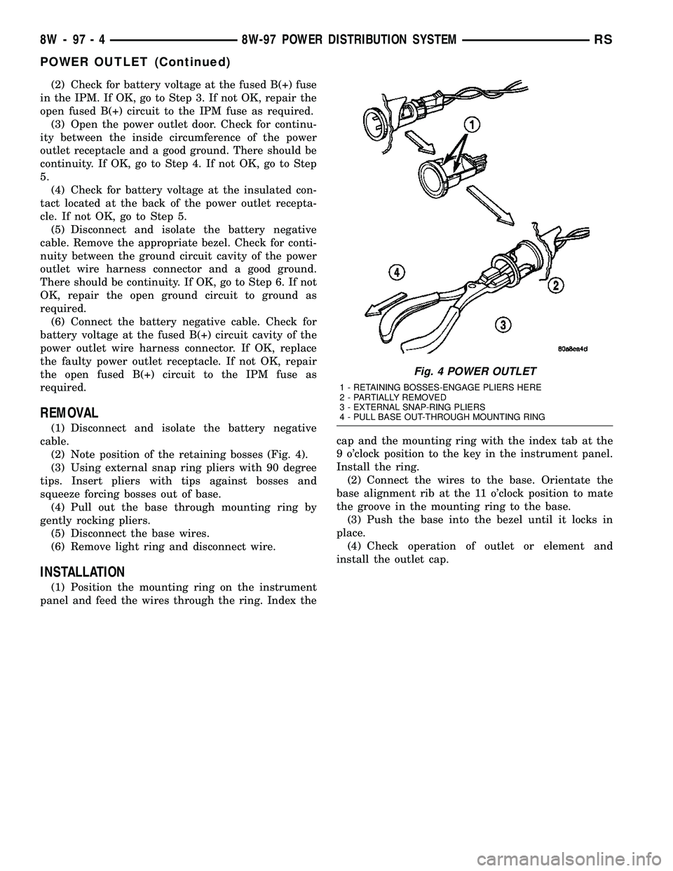
(2) Note position of the retaining bosses (Fig. 4).
(3) Using external snap ring pliers with 90 degree
tips. Insert pliers with tips against bosses and
squeeze forcing bosses out of base.
(4) Pull out the base through mounting ring by
gently rocking pliers.
(5) Disconnect the base wires.
(6) Remove light ring and disconnect wire.
INSTALLATION
(1) Position the mounting ring on the instrument
panel and feed the wires through the ring. Index thecap and the mounting ring with the index tab at the
9 o'clock position to the key in the instrument panel.
Install the ring.
(2) Connect the wires to the base. Orientate the
base alignment rib at the 11 o'clock position to mate
the groove in the mounting ring to the base.
(3) Push the base into the bezel until it locks in
place.
(4) Check operation of outlet or element and
install the outlet cap.
Fig. 4 POWER OUTLET
1 - RETAINING BOSSES-ENGAGE PLIERS HERE
2 - PARTIALLY REMOVED
3 - EXTERNAL SNAP-RING PLIERS
4 - PULL BASE OUT-THROUGH MOUNTING RING
8W - 97 - 4 8W-97 POWER DISTRIBUTION SYSTEMRS
POWER OUTLET (Continued)