2005 CHRYSLER CARAVAN wiring diagram
[x] Cancel search: wiring diagramPage 578 of 2339

Fig. 12 TERMINAL REMOVAL
1 - TYPICAL CONNECTOR
2 - PICK FROM SPECIAL TOOL KIT 6680
3 - APEX CONNECTOR
4 - PICK FROM SPECIAL TOOL KIT 6680
5 - AUGAT CONNECTOR
6 - SPECIAL TOOL 69327 - MOLEX CONNECTOR
8 - SPECIAL TOOL 6742
9 - THOMAS AND BETTS CONNECTOR
10 - SPECIAL TOOL 6934
11 - TYCO CONNECTOR
12 - SPECIAL TOOL 8638
RS8W-01 WIRING DIAGRAM INFORMATION8W-01-13
CONNECTOR (Continued)
Page 579 of 2339

DIODE
REMOVAL
(1) Disconnect the battery.
(2) Locate the diode in the harness, and remove
the protective covering.
(3) Remove the diode from the harness, pay atten-
tion to the current flow direction (Fig. 13).
INSTALLATION
(1) Remove the insulation from the wires in the
harness. Only remove enough insulation to solder in
the new diode.
(2) Install the new diode in the harness, making
sure current flow is correct. If necessary, refer to the
appropriate wiring diagram for current flow (Fig. 13).
(3) Solder the connection together using rosin core
type solder only.Do not use acid core solder.
(4) Tape the diode to the harness using electrical
tape. Make sure the diode is completely sealed from
the elements.
(5) Re-connect the battery and test affected sys-
tems.
TERMINAL
REMOVAL
(1) Follow steps for removing terminals described
in the connector removal section.
(2) Cut the wire 6 inches from the back of the con-
nector.
INSTALLATION
(1) Select a wire from the terminal repair kit that
best matches the color and gage of the wire being
repaired.
(2) Cut the repair wire to the proper length and
remove one±half (1/2) inch of insulation.
(3) Splice the repair wire to the wire harness (see
wire splicing procedure).
(4) Insert the repaired wire into the connector.
(5) Install the connector locking wedge, if required,
and reconnect the connector to its mating half/compo-
nent.
(6) Re-tape the wire harness starting at 1±1/2
inches behind the connector and 2 inches past the
repair.
(7) Connect battery and test all affected systems.
Fig. 13 DIODE IDENTIFICATION
1 - CURRENT FLOW
2 - BAND AROUND DIODE INDICATES CURRENT FLOW
3 - DIODE AS SHOWN IN THE DIAGRAMS
8W - 01 - 14 8W-01 WIRING DIAGRAM INFORMATIONRS
Page 580 of 2339

WIRE
STANDARD PROCEDURE - WIRE SPLICING
When splicing a wire, it is important that the cor-
rect gage be used as shown in the wiring diagrams.
(1) Remove one-half (1/2) inch of insulation from
each wire that needs to be spliced.
(2) Place a piece of adhesive lined heat shrink tub-
ing on one side of the wire. Make sure the tubing will
be long enough to cover and seal the entire repair
area.
(3) Place the strands of wire overlapping each
other inside of the splice clip (Fig. 14).
(4) Using crimping tool, Mopar p/n 05019912AA,
crimp the splice clip and wires together (Fig. 15).(5) Solder the connection together using rosin core
type solder only (Fig. 16).
CAUTION: DO NOT USE ACID CORE SOLDER.
(6) Center the heat shrink tubing over the joint
and heat using a heat gun. Heat the joint until the
tubing is tightly sealed and sealant comes out of both
ends of the tubing (Fig. 17).
Fig. 14 SPLICE BAND
1 - SPLICE BAND
Fig. 15 CRIMPING TOOL
1 - CRIMPING TOOL
Fig. 16 SOLDER SPLICE
1 - SOLDER
2 - SPLICE BAND
3 - SOLDERING IRON
Fig. 17 HEAT SHRINK TUBE
1 - SEALANT
2 - HEAT SHRINK TUBE
RS8W-01 WIRING DIAGRAM INFORMATION8W-01-15
Page 1114 of 2339

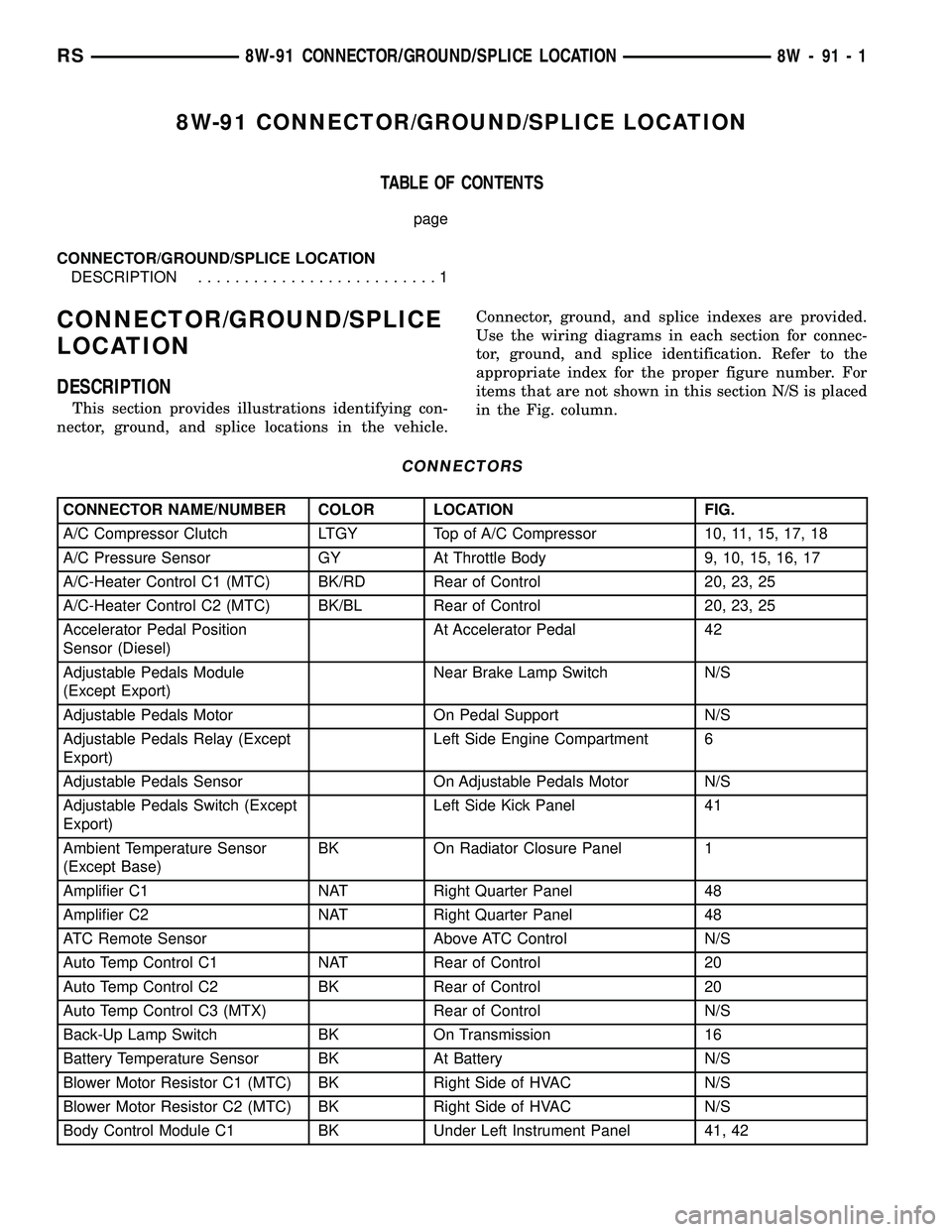
8W-91 CONNECTOR/GROUND/SPLICE LOCATION
TABLE OF CONTENTS
page
CONNECTOR/GROUND/SPLICE LOCATION
DESCRIPTION..........................1
CONNECTOR/GROUND/SPLICE
LOCATION
DESCRIPTION
This section provides illustrations identifying con-
nector, ground, and splice locations in the vehicle.Connector, ground, and splice indexes are provided.
Use the wiring diagrams in each section for connec-
tor, ground, and splice identification. Refer to the
appropriate index for the proper figure number. For
items that are not shown in this section N/S is placed
in the Fig. column.
CONNECTORS
CONNECTOR NAME/NUMBER COLOR LOCATION FIG.
A/C Compressor Clutch LTGY Top of A/C Compressor 10, 11, 15, 17, 18
A/C Pressure Sensor GY At Throttle Body 9, 10, 15, 16, 17
A/C-Heater Control C1 (MTC) BK/RD Rear of Control 20, 23, 25
A/C-Heater Control C2 (MTC) BK/BL Rear of Control 20, 23, 25
Accelerator Pedal Position
Sensor (Diesel)At Accelerator Pedal 42
Adjustable Pedals Module
(Except Export)Near Brake Lamp Switch N/S
Adjustable Pedals Motor On Pedal Support N/S
Adjustable Pedals Relay (Except
Export)Left Side Engine Compartment 6
Adjustable Pedals Sensor On Adjustable Pedals Motor N/S
Adjustable Pedals Switch (Except
Export)Left Side Kick Panel 41
Ambient Temperature Sensor
(Except Base)BK On Radiator Closure Panel 1
Amplifier C1 NAT Right Quarter Panel 48
Amplifier C2 NAT Right Quarter Panel 48
ATC Remote Sensor Above ATC Control N/S
Auto Temp Control C1 NAT Rear of Control 20
Auto Temp Control C2 BK Rear of Control 20
Auto Temp Control C3 (MTX) Rear of Control N/S
Back-Up Lamp Switch BK On Transmission 16
Battery Temperature Sensor BK At Battery N/S
Blower Motor Resistor C1 (MTC) BK Right Side of HVAC N/S
Blower Motor Resistor C2 (MTC) BK Right Side of HVAC N/S
Body Control Module C1 BK Under Left Instrument Panel 41, 42
RS8W-91 CONNECTOR/GROUND/SPLICE LOCATION8W-91-1
Page 1174 of 2339

8W-97 POWER DISTRIBUTION SYSTEM
TABLE OF CONTENTS
page page
POWER DISTRIBUTION SYSTEM
DESCRIPTION..........................1
OPERATION............................1
SPECIAL TOOLS
POWER DISTRIBUTION SYSTEMS.........1
INTEGRATED POWER MODULE
DESCRIPTION..........................1
OPERATION............................2
REMOVAL.............................2
INSTALLATION..........................2IOD FUSE
DESCRIPTION..........................3
OPERATION............................3
POWER OUTLET
DESCRIPTION..........................3
OPERATION............................3
DIAGNOSIS AND TESTING
DIAGNOSIS & TESTING - POWER OUTLET . . 3
REMOVAL.............................4
INSTALLATION..........................4
POWER DISTRIBUTION
SYSTEM
DESCRIPTION
The power distribution system for this vehicle con-
sists of the following components:
²Integrated Power Module (IPM)
²Front Control Module (FCM)
²Power Outlets
Refer to Wiring Diagrams for complete circuit sche-
matics.
The power distribution system also incorporates
various types of circuit control and protection fea-
tures, including:
²Automatic resetting circuit breakers
²Blade-type fuses
²Bus bars
²Cartridge fuses
²Circuit splice blocks
²Flashers
²Fusible links
²Relays
OPERATION
The power distribution system for this vehicle is
designed to provide safe, reliable, and centralized dis-
tribution points for the electrical current required to
operate all of the many standard and optional facto-
ry-installed electrical and electronic powertrain,
chassis, safety, security, comfort and convenience sys-
tems. At the same time, the power distribution sys-
tem was designed to provide ready access to these
electrical distribution points for the vehicle techni-
cian to use when conducting diagnosis and repair of
faulty circuits. The power distribution system can
also prove useful for the sourcing of additional elec-
trical circuits that may be required to provide theelectrical current needed to operate many accessories
that the vehicle owner may choose to have installed.
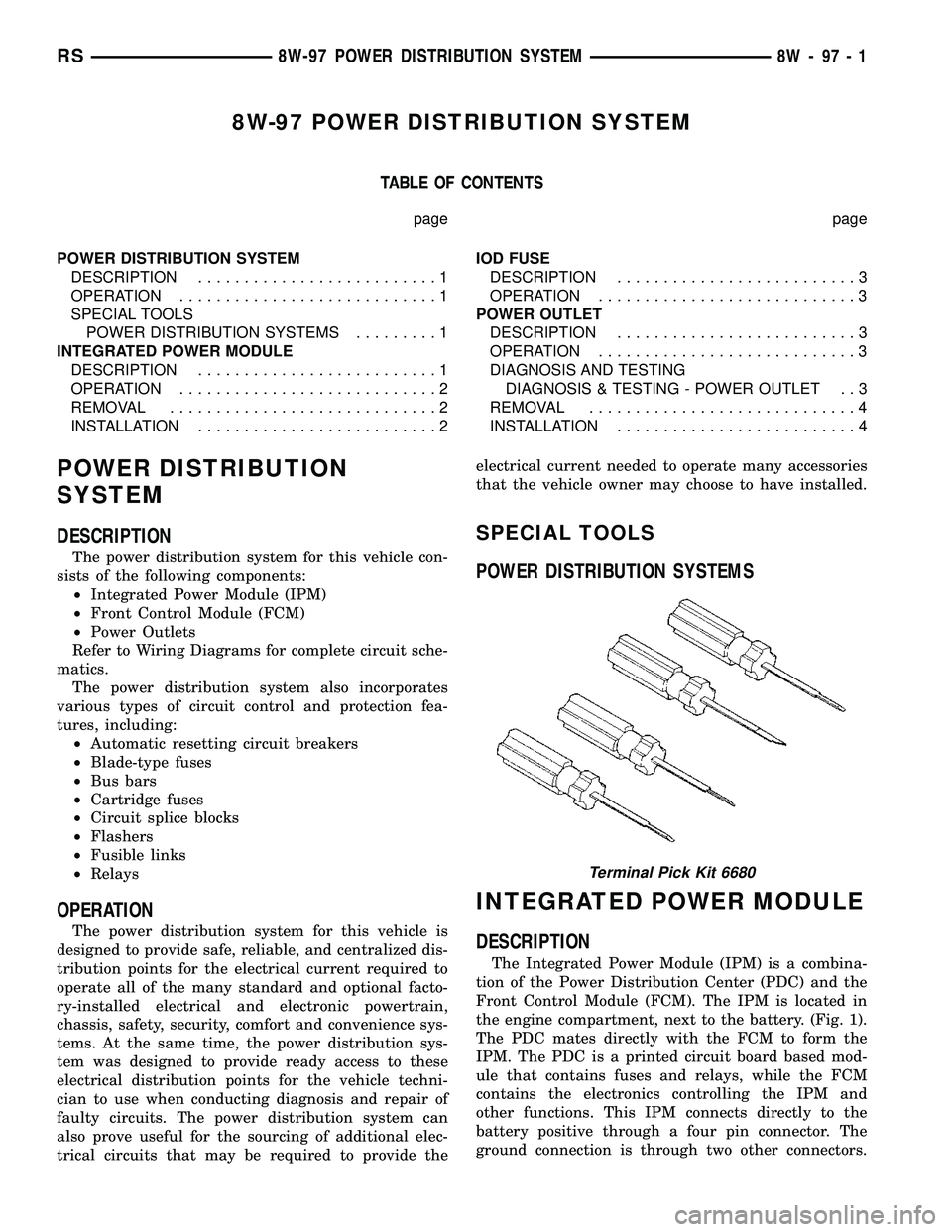
SPECIAL TOOLS
POWER DISTRIBUTION SYSTEMS
INTEGRATED POWER MODULE
DESCRIPTION
The Integrated Power Module (IPM) is a combina-
tion of the Power Distribution Center (PDC) and the
Front Control Module (FCM). The IPM is located in
the engine compartment, next to the battery. (Fig. 1).
The PDC mates directly with the FCM to form the
IPM. The PDC is a printed circuit board based mod-
ule that contains fuses and relays, while the FCM
contains the electronics controlling the IPM and
other functions. This IPM connects directly to the
battery positive through a four pin connector. The
ground connection is through two other connectors.
Terminal Pick Kit 6680
RS8W-97 POWER DISTRIBUTION SYSTEM8W-97-1
Page 1397 of 2339

(5) Rotate injector and pull injector out of fuel rail.
The clip will stay on the injector.
(6) Check injector O-ring for damage. If O-ring is
damaged, it must be replaced. If injector is reused, a
protective cap must be installed on the injector tip to
prevent damage. Replace the injector clip if it is dam-
aged.
(7) Repeat for remaining injectors.
INSTALLATION
INSTALLATION - 2.4L
The fuel rail must be removed first. Refer to Fuel
Injector Rail Removal in this section.
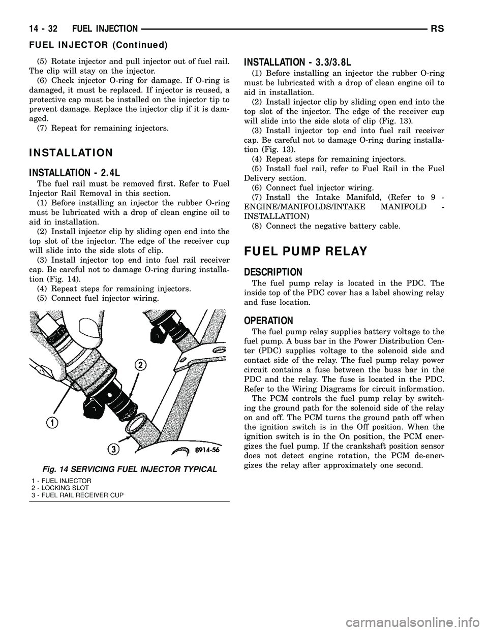
(1) Before installing an injector the rubber O-ring
must be lubricated with a drop of clean engine oil to
aid in installation.
(2) Install injector clip by sliding open end into the
top slot of the injector. The edge of the receiver cup
will slide into the side slots of clip.
(3) Install injector top end into fuel rail receiver
cap. Be careful not to damage O-ring during installa-
tion (Fig. 14).
(4) Repeat steps for remaining injectors.
(5) Connect fuel injector wiring.
INSTALLATION - 3.3/3.8L
(1) Before installing an injector the rubber O-ring
must be lubricated with a drop of clean engine oil to
aid in installation.
(2) Install injector clip by sliding open end into the
top slot of the injector. The edge of the receiver cup
will slide into the side slots of clip (Fig. 13).
(3) Install injector top end into fuel rail receiver
cap. Be careful not to damage O-ring during installa-
tion (Fig. 13).
(4) Repeat steps for remaining injectors.
(5) Install fuel rail, refer to Fuel Rail in the Fuel
Delivery section.
(6) Connect fuel injector wiring.
(7) Install the Intake Manifold, (Refer to 9 -
ENGINE/MANIFOLDS/INTAKE MANIFOLD -
INSTALLATION)
(8) Connect the negative battery cable.
FUEL PUMP RELAY
DESCRIPTION
The fuel pump relay is located in the PDC. The
inside top of the PDC cover has a label showing relay
and fuse location.
OPERATION
The fuel pump relay supplies battery voltage to the
fuel pump. A buss bar in the Power Distribution Cen-
ter (PDC) supplies voltage to the solenoid side and
contact side of the relay. The fuel pump relay power
circuit contains a fuse between the buss bar in the
PDC and the relay. The fuse is located in the PDC.
Refer to the Wiring Diagrams for circuit information.
The PCM controls the fuel pump relay by switch-
ing the ground path for the solenoid side of the relay
on and off. The PCM turns the ground path off when
the ignition switch is in the Off position. When the
ignition switch is in the On position, the PCM ener-
gizes the fuel pump. If the crankshaft position sensor
does not detect engine rotation, the PCM de-ener-
gizes the relay after approximately one second.
Fig. 14 SERVICING FUEL INJECTOR TYPICAL
1 - FUEL INJECTOR
2 - LOCKING SLOT
3 - FUEL RAIL RECEIVER CUP
14 - 32 FUEL INJECTIONRS
FUEL INJECTOR (Continued)
Page 1424 of 2339

(19) Position the lower shroud on the column (Fig.
8). Install the lower shroud mounting screw. Tighten
the screw to 2 N´m (17 in. lbs.) torque.
(20) If equipped with adjustable pedals, Connect
the wiring connector for the switch (Fig. 7) to the col-
umn wiring harness.
(21) Position the upper shroud on top of the lower
shroud and snap it into place. Install the upper
shroud mounting screws (Fig. 6). Tighten the screws
to 2 N´m (17 in. lbs.) torque.
(22) Inspect shroud mating surfaces for excessive
gaps and correct as necessary.
(23) Install the cluster trim bezel (Refer to 23 -
BODY/INSTRUMENT PANEL/CLUSTER BEZEL -
INSTALLATION).
(24) Install the knee blocker/steering column cover
plate. (Refer to 23 - BODY/INSTRUMENT PANEL/
KNEE BLOCKER - INSTALLATION)
(25) Install the parking brake handle link.
(26) Install the knee blocker/steering column open-
ing cover. (Refer to 23 - BODY/INSTRUMENT PAN-
EL/STEERING COLUMN OPENING COVER -
INSTALLATION)
(27) Align the splines and install the steering
wheel on the steering column shaft(Refer to 19 -
STEERING/COLUMN/STEERING WHEEL -
INSTALLATION).
(28) Install the damper over the steering column
shaft (Fig. 4).
(29) Install the steering wheel retaining bolt (Fig.
4). Tighten the bolt to 61 N´m (45 ft. lbs.) torque.
(30) If the steering wheel is equipped with remote
audio controls, connect the wiring connector to the
clockspring (Fig. 4).
(31) Connect the two squib connectors to the
driver airbag (Fig. 3). The connectors are color coded
to avoid connector mix-up.
(32) Connect the speed control and horn connector
to the clockspring (Fig. 3).
(33) Install the airbag to the steering wheel.
Install the driver airbag mounting screws (Fig. 2).
Tighten screws to 10 N´m (90 in. lbs.) torque.
(34) Connect the battery negative (ground) cable to
battery post following special Diagnosis And Testing
procedure. (Refer to 8 - ELECTRICAL/RESTRAINTS
- DIAGNOSIS AND TESTING)
(35) Check operation of all steering column
mounted components.
(36) Road test vehicle to ensure proper operation
of steering.SPECIFICATIONS
COLUMN FASTENER TORQUE
DESCRIPTION N´mFt.
Lbs.In.
Lbs.
Driver Airbag Mounting Screws 10 Ð 90
Multi-Function Switch Mounting
Housing Set-Screw14 Ð 124
Shroud Attaching Screws - Fixed 3 Ð 23
Shroud Attaching Screws -
Lower/Upper2Ð17
SKIM Attaching Screw 4 Ð 30
Steering Column Coupling Pinch
Bolt28 Ð 250
Steering Column Mounting Nuts 12 Ð 105
Steering Wheel Retaining Bolt 61 45 Ð
IGNITION SWITCH
REMOVAL
The ignition switch attaches to the lock cylinder
housing on the end opposite the lock cylinder (Fig.
20). For ignition switch terminal and circuit identifi-
cation, refer to the appropriate wiring information.
The wiring information includes wiring diagrams,
proper wire and connector repair procedures, further
details on wire harness routing and retention, as well
as pin-out and location views for the various wire
harness connectors, splices and grounds.
(1) Disconnect negative cable from battery.
Fig. 20 Ignition SwitchÐViewed From Below
Column
1 - IGNITION SWITCH
2 - LOCK CYLINDER HOUSING
3 - RETAINING TABS
RSCOLUMN19-17
COLUMN (Continued)
Page 1426 of 2339

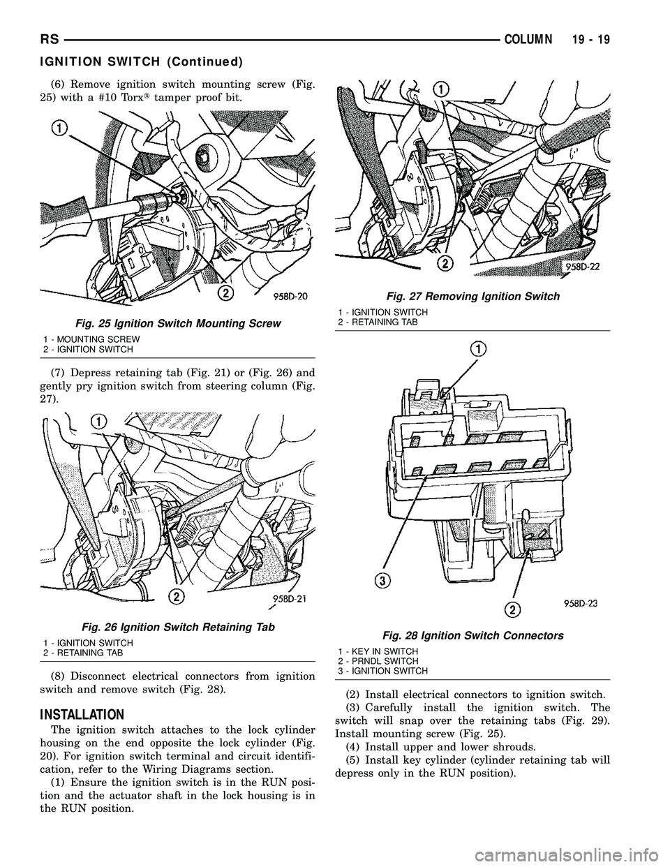
(6) Remove ignition switch mounting screw (Fig.
25) with a #10 Torxttamper proof bit.
(7) Depress retaining tab (Fig. 21) or (Fig. 26) and
gently pry ignition switch from steering column (Fig.
27).
(8) Disconnect electrical connectors from ignition
switch and remove switch (Fig. 28).
INSTALLATION
The ignition switch attaches to the lock cylinder
housing on the end opposite the lock cylinder (Fig.
20). For ignition switch terminal and circuit identifi-
cation, refer to the Wiring Diagrams section.
(1) Ensure the ignition switch is in the RUN posi-
tion and the actuator shaft in the lock housing is in
the RUN position.(2) Install electrical connectors to ignition switch.
(3) Carefully install the ignition switch. The
switch will snap over the retaining tabs (Fig. 29).
Install mounting screw (Fig. 25).
(4) Install upper and lower shrouds.
(5) Install key cylinder (cylinder retaining tab will
depress only in the RUN position).
Fig. 25 Ignition Switch Mounting Screw
1 - MOUNTING SCREW
2 - IGNITION SWITCH
Fig. 26 Ignition Switch Retaining Tab
1 - IGNITION SWITCH
2 - RETAINING TAB
Fig. 27 Removing Ignition Switch
1 - IGNITION SWITCH
2 - RETAINING TAB
Fig. 28 Ignition Switch Connectors
1 - KEY IN SWITCH
2 - PRNDL SWITCH
3 - IGNITION SWITCH
RSCOLUMN19-19
IGNITION SWITCH (Continued)