2005 CHRYSLER CARAVAN air filter
[x] Cancel search: air filterPage 2194 of 2339
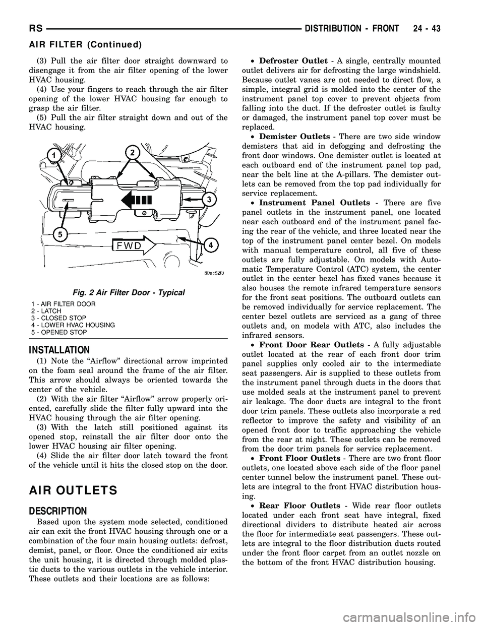
(3) Pull the air filter door straight downward to
disengage it from the air filter opening of the lower
HVAC housing.
(4) Use your fingers to reach through the air filter
opening of the lower HVAC housing far enough to
grasp the air filter.
(5) Pull the air filter straight down and out of the
HVAC housing.
INSTALLATION
(1) Note the ªAirflowº directional arrow imprinted
on the foam seal around the frame of the air filter.
This arrow should always be oriented towards the
center of the vehicle.
(2) With the air filter ªAirflowº arrow properly ori-
ented, carefully slide the filter fully upward into the
HVAC housing through the air filter opening.
(3) With the latch still positioned against its
opened stop, reinstall the air filter door onto the
lower HVAC housing air filter opening.
(4) Slide the air filter door latch toward the front
of the vehicle until it hits the closed stop on the door.
AIR OUTLETS
DESCRIPTION
Based upon the system mode selected, conditioned
air can exit the front HVAC housing through one or a
combination of the four main housing outlets: defrost,
demist, panel, or floor. Once the conditioned air exits
the unit housing, it is directed through molded plas-
tic ducts to the various outlets in the vehicle interior.
These outlets and their locations are as follows:²Defroster Outlet- A single, centrally mounted
outlet delivers air for defrosting the large windshield.
Because outlet vanes are not needed to direct flow, a
simple, integral grid is molded into the center of the
instrument panel top cover to prevent objects from
falling into the duct. If the defroster outlet is faulty
or damaged, the instrument panel top cover must be
replaced.
²Demister Outlets- There are two side window
demisters that aid in defogging and defrosting the
front door windows. One demister outlet is located at
each outboard end of the instrument panel top pad,
near the belt line at the A-pillars. The demister out-
lets can be removed from the top pad individually for
service replacement.
²Instrument Panel Outlets- There are five
panel outlets in the instrument panel, one located
near each outboard end of the instrument panel fac-
ing the rear of the vehicle, and three located near the
top of the instrument panel center bezel. On models
with manual temperature control, all five of these
outlets are fully adjustable. On models with Auto-
matic Temperature Control (ATC) system, the center
outlet in the center bezel has fixed vanes because it
also houses the remote infrared temperature sensors
for the front seat positions. The outboard outlets can
be removed individually for service replacement. The
center bezel outlets are serviced as a gang of three
outlets and, on models with ATC, also includes the
infrared sensors.
²Front Door Rear Outlets- A fully adjustable
outlet located at the rear of each front door trim
panel supplies only cooled air to the intermediate
seat passengers. Air is supplied to these outlets from
the instrument panel through ducts in the doors that
use molded seals at the instrument panel to prevent
air leakage. The door ducts are integral to the front
door trim panels. These outlets also incorporate a red
reflector to improve the safety and visibility of an
opened front door to traffic approaching the vehicle
from the rear at night. These outlets can be removed
from the door trim panels for service replacement.
²Front Floor Outlets- There are two front floor
outlets, one located above each side of the floor panel
center tunnel below the instrument panel. These out-
lets are integral to the front HVAC distribution hous-
ing.
²Rear Floor Outlets- Wide rear floor outlets
located under each front seat have integral, fixed
directional dividers to distribute heated air across
the floor for intermediate seat passengers. These out-
lets are integral to the floor distribution ducts routed
under the front floor carpet from an outlet nozzle on
the bottom of the front HVAC distribution housing.
Fig. 2 Air Filter Door - Typical
1 - AIR FILTER DOOR
2-LATCH
3 - CLOSED STOP
4 - LOWER HVAC HOUSING
5 - OPENED STOP
RSDISTRIBUTION - FRONT24-43
AIR FILTER (Continued)
Page 2224 of 2339
NOTE: Prior to a vehicle being removed from ser-
vice or stored for more than two weeks, the com-
pressor should be operated to ensure adequate
refrigerant oil distribution throughout the system
components. Turn on the air conditioner for a min-
imum of five minutes with outside air and the high-
est blower speed selected.
BELT NOISE
If the compressor drive belt slips at initial start-up,
it does not necessarily mean the compressor has
failed. The following procedure can be used to iden-
tify a compressor drive belt noise problem.
A. Start the vehicle and run at idle.
B. Turn the air conditioner On and listen for belt
squeal.
C. If belt squeal is heard, turn the air conditioner
Off immediately.
If the belt squeal stops when the air conditioner is
turned Off, perform the following repair procedures.
(1) Using an appropriate sized oil filter wrench or
a strap wrench, grasp the outer diameter of the com-
pressor clutch hub. While facing the compressor,
rotate the hub clockwise, then counterclockwise. If
the hub rotates, proceed to the next step. If the hub
will not rotate, the compressor is internally damaged,
and must be replaced.
(2) Turn the hub clockwise five complete revolu-
tions and remove the tool.
(3) Start the vehicle and run at idle.
(4) Turn the air conditioner On. Observe the com-
pressor and the system for normal operation, noting
cooling performance and noise levels. Operate for five
minutes before turning the air conditioner Off. If
acceptable cooling performance is observed during
compressor operation, the compressor does not need
to be replaced.
(5) Inspect the drive belt for wear, damage, and
proper tension. (Refer to 7 - COOLING/ACCESSORY
DRIVE/DRIVE BELTS - DIAGNOSIS AND TEST-
ING).
REMOVAL
A/C COMPRESSOR
WARNING: REFER TO THE APPLICABLE WARN-
INGS AND CAUTIONS FOR THIS SYSTEM BEFORE
PERFORMING THE FOLLOWING OPERATION (Refer
to 24 - HEATING & AIR CONDITIONING/PLUMBING -
FRONT - WARNING - A/C PLUMBING) and (Refer to
24 - HEATING & AIR CONDITIONING/PLUMBING -
FRONT - CAUTION - A/C PLUMBING).(1) Recover the refrigerant from the refrigerant
system (Refer to 24 - HEATING & AIR CONDITION-
ING/PLUMBING - FRONT/REFRIGERANT - STAN-
DARD PROCEDURE - REFRIGERANT SYSTEM
RECOVERY).
(2) Disconnect and isolate the negative battery
cable.
(3) Remove the nuts that secure the A/C suction
line and the A/C discharge line to the A/C compres-
sor.
(4) Disconnect the A/C suction line and the A/C
discharge line from the A/C compressor.
(5) Remove the O-ring seal and gasket from the
suction and discharge line fittings and discard.
(6) Install plugs in, or tape over the opened suc-
tion and discharge fittings and the compressor ports.
(7) Raise and support the vehicle.
(8) Remove the accessory drive belt (Refer to 7 -
COOLING/ACCESSORY DRIVE/DRIVE BELTS -
REMOVAL).
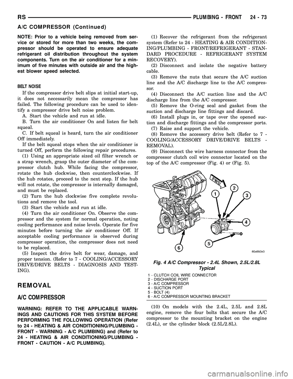
(9) Disconnect the wire harness connector from the
compressor clutch coil wire connector located on the
top of the A/C compressor (Fig. 4) or (Fig. 5).
(10) On models with the 2.4L, 2.5L and 2.8L
engine, remove the four bolts that secure the A/C
compressor to the mounting bracket on the engine
(2.4L), or the cylinder block (2.5L/2.8L).
Fig. 4 A/C Compressor - 2.4L Shown, 2.5L/2.8L
Typical
1 - CLUTCH COIL WIRE CONNECTOR
2 - DISCHARGE PORT
3 - A/C COMPRESSOR
4 - SUCTION PORT
5 - BOLT (4)
6 - A/C COMPRESSOR MOUNTING BRACKET
RSPLUMBING - FRONT24-73
A/C COMPRESSOR (Continued)
Page 2243 of 2339
(7) Lubricate a new rubber O-ring seal with clean
refrigerant oil and install it on the liquid line fitting.
(8) Reconnect the A/C liquid line to the receiver/
drier.
(9) Install the bolt that secures the A/C liquid line
to the receiver/drier. Tighten the bolt to 11 N´m (97
in. lbs.).
(10) If equipped, reinstall the A/C ground strap
eyelet terminal connector onto the weld stud on the
top of the right front strut tower (if equipped).
(11) If equipped, install the nut that secures the
A/C ground strap to the weld stud. Tighten the nut
to 12 N´m (106 in. lbs.)
(12) Install the A/C pressure transducer (Refer to
24 - HEATING & AIR CONDITIONING/CONTROLS
- FRONT/A/C PRESSURE TRANSDUCER - INSTAL-
LATION).
(13) Connect the drain tube to the wiper module
drain on the right side of the engine compartment.
(14) Install the air cleaner housing into the right
side of the engine compartment.
(15) On RHD models, install the liquid line into
the retaining bracket located at the top of the dash
panel.
(16) If the vehicle is equipped with the optional
rear heating-A/C system, go to Step 17. If the vehicle
does not have the optional rear heating-A/C system,
go to Step 23.
(17) Raise and support the vehicle.
(18) Remove the tape or plugs from the A/C liquid
line extension fitting and the underbody liquid line
fitting.
(19) Lubricate a new rubber O-ring seal with clean
refrigerant oil and install it on the underbody liquid
line fitting.
(20) Connect the A/C liquid line extension fitting
to the underbody liquid line fitting. Tighten the fit-
tings to 23 N´m (17 ft. lbs.).
(21) Install a new tie strap just forward of the con-
nections between the underbody plumbing and the
engine compartment plumbing for the rear heating-
A/C system.
(22) Lower the vehicle.
(23) Reconnect the negative battery cable.
(24) Evacuate the refrigerant system (Refer to 24 -
HEATING & AIR CONDITIONING/PLUMBING -
FRONT/REFRIGERANT - STANDARD PROCE-
DURE - REFRIGERANT SYSTEM EVACUATE).
(25) Charge the refrigerant system (Refer to 24 -
HEATING & AIR CONDITIONING/PLUMBING -
FRONT/REFRIGERANT - STANDARD PROCE-
DURE - REFRIGERANT SYSTEM CHARGE).RECEIVER / DRIER
DESCRIPTION
The receiver/drier is mounted in a bracket secured
to the right front strut tower in the engine compart-
ment. The receiver/drier is connected between the
front and rear sections of the liquid line between the
condenser outlet and the evaporator inlet. The receiv-
er/drier cannot be repaired. If the receiver/drier is
faulty or damaged, or if the refrigerant system has
been contaminated or left open to the atmosphere for
an indeterminable period or if the A/C compressor
has failed, it must be replaced.
OPERATION
The receiver/drier performs a filtering action to
prevent foreign material in the refrigerant from con-
taminating the expansion valve. Desiccant inside the
receiver/drier canister absorbs any moisture which
may have entered and become trapped within the
refrigerant system. In addition, during periods of
high demand air conditioner operation, the receiver/
drier acts as a reservoir to store surplus refrigerant.
Refrigerant enters the receiver/drier as a high-pres-
sure, low temperature liquid.
REMOVAL
WARNING: REFER TO THE APPLICABLE WARN-
INGS AND CAUTIONS FOR THIS SYSTEM BEFORE
PERFORMING THE FOLLOWING OPERATION (Refer
to 24 - HEATING & AIR CONDITIONING/PLUMBING -
FRONT - WARNING - A/C PLUMBING) and (Refer to
24 - HEATING & AIR CONDITIONING/PLUMBING -
FRONT - CAUTION - A/C PLUMBING).
(1) Recover the refrigerant from the refrigerant
system (Refer to 24 - HEATING & AIR CONDITION-
ING/PLUMBING - FRONT/REFRIGERANT - STAN-
DARD PROCEDURE - REFRIGERANT
RECOVERY).
(2) Remove the air cleaner housing from the right
side of the engine compartment.
(3) Remove the bolt that secures the liquid line
front section fitting to the top of the receiver/drier
(Fig. 30).
(4) Disconnect the liquid line fitting from the
receiver/drier inlet port.
(5) Remove the O-ring seal from the liquid line fit-
ting and discard.
(6) Install plugs in, or tape over the opened liquid
line fitting and the receiver/drier inlet port.
24 - 92 PLUMBING - FRONTRS
LIQUID LINE (Continued)
Page 2279 of 2339
The major non-monitored circuits are listed below
along with examples of failures modes that do not
directly cause the PCM to set a DTC, but for a sys-
tem that is monitored.
FUEL PRESSURE
The fuel pressure regulator controls fuel system
pressure. The PCM cannot detect a clogged fuel
pump inlet filter, clogged in-line fuel filter, or a
pinched fuel supply or return line. However, these
could result in a rich or lean condition causing the
PCM to store an oxygen sensor, fuel system, or mis-
fire diagnostic trouble code.
SECONDARY IGNITION CIRCUIT
The PCM cannot detect an inoperative ignition coil,
fouled or worn spark plugs, ignition cross firing, or
open spark plug cables. The misfire will however,
increase the oxygen content in the exhaust, deceiving
the PCM in to thinking the fuel system is too lean.
Also see misfire detection. There are DTC's that can
detect misfire and Ionization shorts in the secondary
ignition circuit, refer to the Powertrain Diagnostic
manual for more information
CYLINDER COMPRESSION
The PCM cannot detect uneven, low, or high engine
cylinder compression. Low compression lowers O2
content in the exhaust. Leading to fuel system, oxy-
gen sensor, or misfire detection fault.
EXHAUST SYSTEM
The PCM cannot detect a plugged, restricted or
leaking exhaust system. It may set a EGR (if
equipped) or Fuel system or O2S fault.
FUEL INJECTOR MECHANICAL MALFUNCTIONS
The PCM cannot determine if a fuel injector is
clogged, the needle is sticking or if the wrong injector
is installed. However, these could result in a rich or
lean condition causing the PCM to store a diagnostic
trouble code for either misfire, an oxygen sensor, or
the fuel system.
EXCESSIVE OIL CONSUMPTION
Although the PCM monitors engine exhaust oxygen
content when the system is in closed loop, it cannot
determine excessive oil consumption.
THROTTLE BODY AIR FLOW
The PCM cannot detect a clogged or restricted air
cleaner inlet or filter element.
VACUUM ASSIST
The PCM cannot detect leaks or restrictions in the
vacuum circuits of vacuum assisted engine control
system devices. However, these could cause the PCMto store a MAP sensor diagnostic trouble code and
cause a high idle condition.
PCM SYSTEM GROUND
The PCM cannot determine a poor system ground.
However, one or more diagnostic trouble codes may
be generated as a result of this condition. The mod-
ule should be mounted to the body at all times,
including when diagnostics are performed.
PCM CONNECTOR ENGAGEMENT
The PCM may not be able to determine spread or
damaged connector pins. However, it might store
diagnostic trouble codes as a result of spread connec-
tor pins.
DESCRIPTION - MONITORED SYSTEMS
There are new electronic circuit monitors that
check fuel, emission, engine and ignition perfor-
mance. These monitors use information from various
sensor circuits to indicate the overall operation of the
fuel, engine, ignition and emission systems and thus
the emissions performance of the vehicle.
The fuel, engine, ignition and emission systems
monitors do not indicate a specific component prob-
lem. They do indicate that there is an implied prob-
lem within one of the systems and that a specific
problem must be diagnosed.
If any of these monitors detect a problem affecting
vehicle emissions, the Malfunction Indicator (Check
Engine) Lamp will be illuminated. These monitors
generate Diagnostic Trouble Codes that can be dis-
played with the a scan tool.
The following is a list of the system monitors:
²EGR Monitor (if equipped)
²Misfire Monitor
²Fuel System Monitor
²Oxygen Sensor Monitor
²Oxygen Sensor Heater Monitor
²Catalyst Monitor
²Evaporative System Leak Detection Monitor (if
equipped)
Following is a description of each system monitor,
and its DTC.
Refer to the appropriate Powertrain Diagnos-
tics Procedures manual for diagnostic proce-
dures.
OXYGEN SENSOR (O2S) MONITOR
Effective control of exhaust emissions is achieved
by an oxygen feedback system. The most important
element of the feedback system is the O2S. The O2S
is located in the exhaust path. Once it reaches oper-
ating temperatures of 300É to 350ÉC (572É to 662ÉF),
the sensor generates a voltage that is inversely pro-
portional to the amount of oxygen in the exhaust.
25 - 6 EMISSIONS CONTROLRS
EMISSIONS CONTROL (Continued)
Page 2281 of 2339
tion occurs such that the PCM cannot maintain the
optimum A/F ratio, then the MIL will be illuminated.
CATALYST MONITOR
To comply with clean air regulations, vehicles are
equipped with catalytic converters. These converters
reduce the emission of hydrocarbons, oxides of nitro-
gen and carbon monoxide.
Normal vehicle miles or engine misfire can cause a
catalyst to decay. A meltdown of the ceramic core can
cause a reduction of the exhaust passage. This can
increase vehicle emissions and deteriorate engine
performance, driveability and fuel economy.
The catalyst monitor uses dual oxygen sensors
(O2S's) to monitor the efficiency of the converter. The
dual O2S's strategy is based on the fact that as a cat-
alyst deteriorates, its oxygen storage capacity and its
efficiency are both reduced. By monitoring the oxy-
gen storage capacity of a catalyst, its efficiency can
be indirectly calculated. The upstream O2S is used to
detect the amount of oxygen in the exhaust gas
before the gas enters the catalytic converter. The
PCM calculates the A/F mixture from the output of
the O2S. A low voltage indicates high oxygen content
(lean mixture). A high voltage indicates a low content
of oxygen (rich mixture).
When the upstream O2S detects a lean condition,
there is an abundance of oxygen in the exhaust gas.
A functioning converter would store this oxygen so it
can use it for the oxidation of HC and CO. As the
converter absorbs the oxygen, there will be a lack of
oxygen downstream of the converter. The output of
the downstream O2S will indicate limited activity in
this condition.
As the converter loses the ability to store oxygen,
the condition can be detected from the behavior of
the downstream O2S. When the efficiency drops, no
chemical reaction takes place. This means the con-
centration of oxygen will be the same downstream as
upstream. The output voltage of the downstream
O2S copies the voltage of the upstream sensor. The
only difference is a time lag (seen by the PCM)
between the switching of the O2S's.
To monitor the system, the number of lean-to-rich
switches of upstream and downstream O2S's is
counted. The ratio of downstream switches to
upstream switches is used to determine whether the
catalyst is operating properly. An effective catalyst
will have fewer downstream switches than it has
upstream switches i.e., a ratio closer to zero. For a
totally ineffective catalyst, this ratio will be one-to-
one, indicating that no oxidation occurs in the device.
The system must be monitored so that when cata-
lyst efficiency deteriorates and exhaust emissions
increase to over the legal limit, the MIL (Check
Engine lamp) will be illuminated.NATURAL VACUUM LEAK DETECTION (NVLD) (if equipped)
The Natural Vacuum Leak Detection (NVLD) sys-
tem is the next generation evaporative leak detection
system that will first be used on vehicles equipped
with the Next Generation Controller (NGC). This
new system replaces the leak detection pump as the
method of evaporative system leak detection. This is
to detect a leak equivalent to a 0.0209(0.5 mm) hole.
This system has the capability to detect holes of this
size very dependably.
The basic leak detection theory employed with
NVLD is the9Gas Law9. This is to say that the pres-
sure in a sealed vessel will change if the temperature
of the gas in the vessel changes. The vessel will only
see this effect if it is indeed sealed. Even small leaks
will allow the pressure in the vessel to come to equi-
librium with the ambient pressure. In addition to the
detection of very small leaks, this system has the
capability of detecting medium as well as large evap-
orative system leaks.
The NVLD seals the canister vent during engine
off conditions. If the EVAP system has a leak of less
than the failure threshold, the evaporative system
will be pulled into a vacuum, either due to the cool
down from operating temperature or diurnal ambient
temperature cycling. The diurnal effect is considered
one of the primary contributors to the leak determi-
nation by this diagnostic. When the vacuum in the
system exceeds about 19H2O (0.25 KPA), a vacuum
switch closes. The switch closure sends a signal to
the NGC. The NGC, via appropriate logic strategies
(described below), utilizes the switch signal, or lack
thereof, to make a determination of whether a leak is
present.
The NVLD device is designed with a normally open
vacuum switch, a normally closed solenoid, and a
seal, which is actuated by both the solenoid and a
diaphragm. The NVLD is located on the atmospheric
vent side of the canister. The NVLD assembly may
be mounted on top of the canister outlet, or in-line
between the canister and atmospheric vent filter. The
normally open vacuum switch will close with about 19
H2O (0.25 KPA) vacuum in the evaporative system.
The diaphragm actuates the switch. This is above the
opening point of the fuel inlet check valve in the fill
tube so cap off leaks can be detected. Submerged fill
systems must have recirculation lines that do not
have the in-line normally closed check valve that pro-
tects the system from failed nozzle liquid ingestion,
in order to detect cap off conditions.
The normally closed valve in the NVLD is intended
to maintain the seal on the evaporative system dur-
ing the engine off condition. If vacuum in the evapo-
rative system exceeds 39to 69H2O (0.75 to 1.5 KPA),
the valve will be pulled off the seat, opening the seal.
This will protect the system from excessive vacuum
25 - 8 EMISSIONS CONTROLRS
EMISSIONS CONTROL (Continued)
Page 2302 of 2339
INDEX
ABS FASTENER TORQUE,SPECIFICATIONS ...................... 5-91
ABSORBER - DESCRIPTION, SHOCK .......2-36
ABSORBER - INSTALLATION, SHOCK ......2-38
ABSORBER - OPERATION, SHOCK ........2-36
ABSORBER - REMOVAL, SHOCK ..........2-36
ABSORBER (UPPER BUSHING) - ASSEMBLY, SHOCK .................... 2-37
ABSORBER (UPPER BUSHING) - DISASSEMBLY, SHOCK .................2-37
A/C CLUTCH BREAK-IN, STANDARD PROCEDURE ........................ 24-15
A/C COMPRESSOR CLUTCH COIL, DIAGNOSIS AND TESTING .............24-14
A/C COMPRESSOR CLUTCH RELAY - DESCRIPTION ....................... 24-18
A/C COMPRESSOR CLUTCH RELAY - INSTALLATION ....................... 24-19
A/C COMPRESSOR CLUTCH RELAY - OPERATION ......................... 24-18
A/C COMPRESSOR CLUTCH RELAY - REMOVAL .......................... 24-19
A/C COMPRESSOR CLUTCH/COIL - DESCRIPTION ....................... 24-13
A/C COMPRESSOR CLUTCH/COIL - OPERATION ......................... 24-13
A/C COMPRESSOR, DESCRIPTION .......24-72
A/C COMPRESSOR, INSTALLATION .......24-74
A/C COMPRESSOR MOUNTING BRACKET, 2.4L ENGINE ...........24-74,24-75
A/C COMPRESSOR NOISE DIAGNOSIS, DIAGNOSIS AND TESTING .............24-72
A/C COMPRESSOR, OPERATION .........24-72
A/C COMPRESSOR, REMOVAL ..........24-73
A/C CONDENSER - DESCRIPTION ........24-75
A/C CONDENSER - OPERATION ..........24-75
A/C COOL DOWN TEST, DIAGNOSIS AND TESTING ............................ 24-6
A/C DISCHARGE LINE - INSTALLATION . . . 24-80
A/C DISCHARGE LINE - REMOVAL .......24-79
A/C EVAPORATOR - DESCRIPTION . . 24-80,24-98
A/C EVAPORATOR - INSTALLATION ......24-81
A/C EVAPORATOR - OPERATION ....24-80,24-98
A/C EVAPORATOR - REMOVAL ..........24-81
A/C EVAPORATOR, INSTALLATION - REAR ............................. 24-100
A/C EVAPORATOR LINE EXTENSION, INSTALLATION - REAR ...............24-100
A/C EVAPORATOR LINE EXTENSION, REMOVAL - REAR .................... 24-99
A/C EVAPORATOR, REMOVAL - REAR .....24-98
A/C EXPANSION VALVE - DESCRIPTION . . 24-100
A/C EXPANSION VALVE - OPERATION ....24-100
A/C EXPANSION VALVE, DIAGNOSIS AND TESTING - FRONT .................... 24-82
A/C EXPANSION VALVE, DIAGNOSIS AND TESTING - REAR .................... 24-101
A/C HEATER CONTROL - DESCRIPTION . . . 24-19
A/C PERFORMANCE TEST, DIAGNOSIS AND TESTING ........................ 24-7
A/C PRESSURE TRANSDUCER - DESCRIPTION ....................... 24-20
A/C PRESSURE TRANSDUCER - OPERATION ......................... 24-20
A/C PRESSURE TRANSDUCER, DIAGNOSIS AND TESTING .............24-21
A/C SYSTEM - CAUTION ...............24-66
A/C SYSTEM, SPECIFICATIONS ..........24-11
A/C SYSTEM, WARNING ...............24-66
ACCELERATOR PEDAL - INSTALLATION . . . 14-28
ACCELERATOR PEDAL - REMOVAL .......14-28
ACCESSORY DRIVE BELT - DIAGNOSIS AND TESTING .........................7-7
ACCESSORY DRIVE BELT TENSION, SPECIFICATIONS .......................7-5
ACCUMULATOR - DESCRIPTION . . . 21-218,21-73
ACCUMULATOR - OPERATION ....21-218,21-73
A/C-HEATER CONTROL - DESCRIPTION . . . 24-33
A/C-HEATER CONTROL - INSTALLATION . . . 24-34
A/C-HEATER CONTROL - OPERATION .....24-33
A/C-HEATER CONTROL - REMOVAL ......24-33
A/C-HEATER CONTROL CALIBRATION, STANDARD PROCEDURE ...............24-19
ACTUATOR - DESCRIPTION, BLEND DOOR ........................ 24-22,24-34
ACTUATOR - DESCRIPTION, ENGAGE ......8N-9
ACTUATOR - DESCRIPTION, LATCH ......8N-13 ACTUATOR - DESCRIPTION, MODE
DOOR ............................. 24-29
ACTUATOR - DESCRIPTION, RECIRCULATION DOOR ................24-31
ACTUATOR - INSTALLATION, BLEND DOOR ........................ 24-22,24-35
ACTUATOR - INSTALLATION, ENGAGE ....8N-10
ACTUATOR - INSTALLATION, INSIDE HANDLE ............................ 23-27
ACTUATOR - INSTALLATION, LATCH .....8N-14
ACTUATOR - INSTALLATION, MODE DOOR ............................. 24-30
ACTUATOR - INSTALLATION, RECIRCULATION DOOR ................24-32
ACTUATOR - OPERATION, BLEND DOOR . . 24-22, 24-35
ACTUATOR - OPERATION, ENGAGE .......8N-9
ACTUATOR - OPERATION, LATCH ........8N-13
ACTUATOR - OPERATION, MODE DOOR . . . 24-29
ACTUATOR - OPERATION, RECIRCULATION DOOR ................24-31
ACTUATOR - REAR - DESCRIPTION, MODE DOOR ........................ 24-39
ACTUATOR - REAR - INSTALLATION, MODE DOOR ........................ 24-40
ACTUATOR - REAR - OPERATION, MODE DOOR ............................. 24-39
ACTUATOR - REAR - REMOVAL, MODE DOOR ............................. 24-39
ACTUATOR - REMOVAL, BLEND DOOR . . . 24-22, 24-35
ACTUATOR - REMOVAL, ENGAGE ..........8N-9
ACTUATOR - REMOVAL, INSIDE HANDLE . . 23-27
ACTUATOR - REMOVAL, LATCH .........8N-13
ACTUATOR - REMOVAL, MODE DOOR ....24-29
ACTUATOR - REMOVAL, RECIRCULATION DOOR ............................. 24-32
ADAPTER - INSTALLATION, FRONT DISC BRAKE CALIPER ...................... 5-31
ADAPTER - INSTALLATION, OIL FILTER . . . 9-142
ADAPTER - REMOVAL, FRONT DISC BRAKE CALIPER ...................... 5-31
ADAPTER - REMOVAL, OIL FILTER .......9-142
ADAPTIVE MEMORIES, OPERATION - FUEL CORRECTION OR ................14-24
ADDING ADDITIONAL COOLANT - STANDARD PROCEDURE .................7-4
ADDITIONAL COOLANT - STANDARD PROCEDURE, ADDING ...................7-4
ADHESIVE ATTACHED - INSTALLATION, EXTERIOR NAME PLATES ..............23-51
ADHESIVE ATTACHED - REMOVAL, EXTERIOR NAME PLATES ..............23-51
ADHESIVE LOCATIONS - FOLD-IN-FLOOR ONLY - SPECIFICATIONS,
STRUCTURAL ...................... 23-228
ADHESIVE LOCATIONS - SPECIFICATIONS, STRUCTURAL ........23-218
ADJUSTABLE - INSTALLATION, PEDALS ....5-43
ADJUSTABLE - REMOVAL, PEDALS .......5-40
ADJUSTABLE PEDALS SWITCH - INSTALLATION ........................ 5-11
ADJUSTABLE PEDALS SWITCH - REMOVAL ........................... 5-11
ADJUSTE R-BOR C-PILLAR -
INSTALLATION, SEAT BELT HEIGHT ......8O-38
ADJUSTE R-BOR C-PILLAR -
REMOVAL, SEAT BELT HEIGHT ..........8O-38
ADJUSTER - DIAGNOSIS AND TESTING, DRUM BRAKE AUTOMATIC ..............5-14
ADJUSTER - INSTALLATION, FRONT SEAT TRACK MANUAL ...............23-126
ADJUSTER - INSTALLATION, FRONT SEAT TRACK POWER ................23-124
ADJUSTER - REMOVAL, FRONT SEAT TRACK MANUAL .................... 23-125
ADJUSTER - REMOVAL, FRONT SEAT TRACK POWER ..................... 23-124
ADJUSTER KNOB - INSTALLATION, SEAT BELT HEIGHT ....................... 8O-38
ADJUSTER KNOB - REMOVAL, SEAT BELT HEIGHT ....................... 8O-38
ADJUSTER NOISE DIAGNOSIS - DIAGNOSIS AND TESTING, HYDRAULIC
LASH ............................... 9-34
ADJUSTER TENSION RELEASE - STANDARD PROCEDURE, PARKING
BRAKE AUTOMATIC .................... 5-63ADJUSTER TENSION RESET -
STANDARD PROCEDURE, PARKING
BRAKE AUTOMATIC .................... 5-64
ADJUSTER/MANUAL - OCS - INSTALLATION, FRONT SEAT TRACK ....23-128
ADJUSTER/MANUAL - OCS - REMOVAL, FRONT SEAT TRACK .................23-126
ADJUSTER/POWER - OCS - INSTALLATION, FRONT SEAT TRACK ....23-125
ADJUSTER/POWER - OCS - REMOVAL, FRONT SEAT TRACK .................23-124
ADJUSTERS - INSTALLATION, HYDRAULIC LASH ..................... 9-35
ADJUSTERS - REMOVAL, HYDRAULIC LASH ............................... 9-35
AERATION - DIAGNOSIS AND TESTING, COOLING SYSTEM .....................7-4
AFTER AN AIRBAG DEPLOYMENT - STANDARD PROCEDURE, SERVICE .......8O-7
AIR CLEANER ELEMENT - INSTALLATION . 9-101, 9-24
AIR CLEANER ELEMENT - REMOVAL . 9-101,9-24
AIR CLEANER HOUSING - INSTALLATION . 9-102, 9-25
AIR CLEANER HOUSING - REMOVAL . 9-101,9-25
AIR CONDITIONER, DESCRIPTION - HEATER ............................. 24-1
AIR CONDITIONER, OPERATION - HEATER ............................. 24-4
AIR CONTROL MOTOR - DESCRIPTION, IDLE ............................... 14-33
AIR CONTROL MOTOR - INSTALLATION, IDLE ............................... 14-33
AIR CONTROL MOTOR - OPERATION, IDLE ............................... 14-33
AIR CONTROL MOTOR - REMOVAL, IDLE . . 14-33
AIR EXHAUSTER - DESCRIPTION, REAR QUARTER PANEL/FENDER ..............23-59
AIR EXHAUSTER - INSTALLATION, REAR QUARTER PANEL/FENDER ..............23-60
AIR EXHAUSTER - REMOVAL, REAR QUARTER PANEL/FENDER ..............23-59
AIR FILTER - DESCRIPTION ............24-42
AIR FILTER - INSTALLATION ............24-43
AIR FILTER - REMOVAL ...............24-42
AIR GAP, SPECIFICATIONS - WHEEL SPEED SENSOR ....................... 5-91
AIR INTAKE PIPE - INSTALLATION ......24-115
AIR INTAKE PIPE - REMOVAL ..........24-115
AIR OUTLETS - DESCRIPTION .....24-43,24-56
AIR OUTLETS - INSTALLATION ..........24-56
AIR OUTLETS - REMOVAL .............24-56
AIR PRESSURE TESTS - DIAGNOSIS AND TESTING, CLUTCH ...........21-153,21-8
AIR TEMPERATURE SENSOR - DESCRIPTION, INLET .................14-34
AIRBAG - DESCRIPTION, CURTAIN .......8O-12
AIRBAG - DESCRIPTION, DRIVER ........8O-16
AIRBAG - DESCRIPTION, KNEE BLOCKER . 8O-22
AIRBAG - DESCRIPTION, PASSENGER ....8O-30
AIRBAG - INSTALLATION, CURTAIN ......8O-16
AIRBAG - INSTALLATION, DRIVER .......8O-18
AIRBAG - INSTALLATION, KNEE BLOCKER .......................... 8O-23
AIRBAG - INSTALLATION, PASSENGER . . . 8O-32
AIRBAG - OPERATION, CURTAIN ........8O-13
AIRBAG - OPERATION, DRIVER .........8O-16
AIRBAG - OPERATION, KNEE BLOCKER . . . 8O-22
AIRBAG - OPERATION, PASSENGER ......8O-30
AIRBAG - REMOVAL, CURTAIN ..........8O-14
AIRBAG - REMOVAL, DRIVER ...........8O-17
AIRBAG - REMOVAL, KNEE BLOCKER ....8O-23
AIRBAG - REMOVAL, PASSENGER .......8O-30
AIRBAG DEPLOYMENT - STANDARD PROCEDURE, SERVICE AFTER AN ........8O-7
AIRBAG DISABLED INDICATOR - DESCRIPTION, PASSENGER ............8O-33
AIRBAG DISABLED INDICATOR - INSTALLATION, PASSENGER ...........8O-34
AIRBAG DISABLED INDICATOR - OPERATION, PASSENGER ..............8O-33
AIRBAG DISABLED INDICATOR - REMOVAL, PASSENGER ...............8O-34
AIRBAG SYSTEM - DIAGNOSIS AND TESTING ............................ 8O-6
AIRBAGS - STANDARD PROCEDURE, HANDLING .......................... 8O-6
RS INDEX1
Description Group-Page Description Group-Page Description Group-Page
Page 2312 of 2339
DOOR WEATHERSTRIP - INSTALLATION,SLIDING ........................... 23-168
DOOR WEATHERSTRIP - REMOVAL, FRONT ............................ 23-168
DOOR WEATHERSTRIP - REMOVAL, SLIDING ........................... 23-168
DOSING PUMP - DESCRIPTION, FUEL . . . 24-117
DOSING PUMP - INSTALLATION, FUEL . . . 24-117
DOSING PUMP - OPERATION, FUEL .....24-117
DOSING PUMP - REMOVAL, FUEL ......24-117
DOWNSTREAM 1/2 - 2.4/3.3/3.8L - REMOVAL .......................... 14-38
DOWNSTREAM 2/1, 2.4/3.3/3.8L - INSTALLATION ....................... 14-39
D-PILLAR TRIM PANEL - INSTALLATION, LEFT .............................. 23-94
D-PILLAR TRIM PANEL - INSTALLATION, RIGHT ............................. 23-98
D-PILLAR TRIM PANEL - REMOVAL, LEFT .............................. 23-94
D-PILLAR TRIM PANEL - REMOVAL, RIGHT ............................. 23-97
DRAIN TUBE - INSTALLATION ..........23-172
DRAIN TUBE - REMOVAL .............23-172
DRAINCOCK - INSTALLATION, RADIATOR . . . 7-27
DRAINCOCK - REMOVAL, RADIATOR ......7-27
DRAINING - STANDARD PROCEDURE, COOLING SYSTEM .....................7-4
DRAINING FUEL TANK - STANDARD PROCEDURE ......................... 14-2
DRAW TEST, STANDARD PROCEDURE - IGNITION-OFF ....................... 8F-13
DRB III TSTATE DISPLAY TEST MODE,
OPERATION ......................... 25-10
DRIER - DESCRIPTION, RECEIVER .......24-92
DRIER - INSTALLATION, RECEIVER ......24-93
DRIER - OPERATION, RECEIVER .........24-92
DRIER - REMOVAL, RECEIVER ..........24-92
DRIVE - ASSEMBLY, FINAL .......21-224,21-78
DRIVE - DESCRIPTION, FINAL ....21-219,21-74
DRIVE - DESCRIPTION, FLEX ...........8N-55
DRIVE - DISASSEMBLY, FINAL ....21-220,21-75
DRIVE - INSTALLATION, FLEX ..........8N-56
DRIVE - OPERATION, FINAL ......21-220,21-75
DRIVE - OPERATION, FLEX .............8N-55
DRIVE - REMOVAL, FLEX ..............8N-55
DRIVE BELT - DIAGNOSIS AND TESTING, ACCESSORY ..........................7-7
DRIVE BELT TENSION, SPECIFICATIONS - ACCESSORY ..........................7-5
DRIVE BELTS - 2.4L - ADJUSTMENTS .....7-10
DRIVE BELTS - 2.4L - INSTALLATION .......7-9
DRIVE BELTS - 2.4L - REMOVAL ..........7-9
DRIVE BELTS - 3.3/3.8L - INSTALLATION . . . 7-12
DRIVE BELTS - 3.3/3.8L - REMOVAL ......7-11
DRIVE BELTS - CLEANING ...............7-8
DRIVE BELTS - INSPECTION ..............7-8
DRIVE UNIT - DESCRIPTION, LOWER ....8N-53
DRIVE UNIT - INSTALLATION, LOWER ....8N-54
DRIVE UNIT - OPERATION, LOWER ......8N-53
DRIVE UNIT - REMOVAL, LOWER .......8N-53
DRIVE UNIT TRACK & RACK - DESCRIPTION, LOWER ................8N-57
DRIVE UNIT TRACK & RACK - INSTALLATION, LOWER ...............8N-58
DRIVE UNIT TRACK & RACK - OPERATION, LOWER .................. 8N-57
DRIVE UNIT TRACK & RACK - REMOVAL, LOWER ................... 8N-57
DRIVELINE MODULE FLUIDS - DESCRIPTION, AWD REAR ...............0-6
DRIVER AIRBAG - DESCRIPTION ........8O-16
DRIVER AIRBAG - INSTALLATION .......8O-18
DRIVER AIRBAG - OPERATION ..........8O-16
DRIVER AIRBAG - REMOVAL ...........8O-17
DRIVER HEATED SEAT SWITCH, DIAGNOSIS AND TESTING ..............8G-9
DRIVER SEAT SWITCH, DIAGNOSIS AND TESTING ........................... 8N-34
DRIVING CLUTCHES - DESCRIPTION ....21-219,
21-74
DRIVING CLUTCHES - OPERATION . 21-219,21-74
DROP - STANDARD PROCEDURE, TESTING FOR A VOLTAGE ...........8W-01-10
DRUM - INSTALLATION .................5-32
DRUM - REMOVAL .................... 5-32
DRUM BRAKE - INSTALLATION, SUPPORT PLATE ...................... 5-61DRUM BRAKE - REMOVAL, SUPPORT
PLATE .............................. 5-61
DRUM BRAKE AUTOMATIC ADJUSTER - DIAGNOSIS AND TESTING ..............5-14
DRUM BRAKE SHOE LINING - INSPECTION, REAR .................... 5-22
DRUM BRAKE SHOES - ADJUSTMENT, REAR ............................... 5-23
DRUM BRAKE SHOES - INSTALLATION, REAR ............................... 5-22
DRUM BRAKE SHOES - REMOVAL, REAR . . 5-19
DRUM BRAKES (REAR) - DESCRIPTION ....5-13
DUAL ZONE, DESCRIPTION - MANUAL .....24-2
DUAL ZONE, OPERATION - MANUAL ......24-5
DUCT - INSTALLATION, DEFROSTER .....24-50
DUCT - INSTALLATION, DISTRIBUTION . . . 24-57
DUCT - INSTALLATION, REAR FLOOR HEAT .............................. 24-63
DUCT - REMOVAL, DEFROSTER .........24-49
DUCT - REMOVAL, DISTRIBUTION .......24-57
DUCT - REMOVAL, REAR FLOOR HEAT . . . 24-63
DUCTS - INSTALLATION, FLOOR DISTRIBUTION ....................... 24-50
DUCTS - INSTALLATION, INSTRUMENT PANEL ............................. 24-55
DUCTS - INSTALLATION, INSTRUMENT PANEL DEMISTER .................... 24-54
DUCTS - REMOVAL, FLOOR DISTRIBUTION ....................... 24-50
DUCTS - REMOVAL, INSTRUMENT PANEL .............................. 24-55
DUCTS - REMOVAL, INSTRUMENT PANEL DEMISTER .................... 24-54
DUTY, CARGO - INSTALLATION, AWD, HEAVY.............................. 2-36
DUTY, CARGO - REMOVAL, AWD, HEAVY . . . 2-36
DVD PLAYER - DESCRIPTION ...........8A-12
DVD PLAYER - INSTALLATION ..........8A-12
DVD PLAYER - REMOVAL ..............8A-12
ELECTRIC BACKLIGHT (EBL) SYSTEM, DIAGNOSIS AND TESTING ..............8G-2
ELECTROLYTE LEVEL, STANDARD PROCEDURE - CHECKING BATTERY ......8F-14
ELECTRONIC VARIABLE BRAKE PROPORTIONING - DESCRIPTION ........5-88
ELECTRONIC VARIABLE BRAKE PROPORTIONING - OPERATION ..........5-89
ELECTRONIC VEHICLE INFO CENTER - DESCRIPTION ........................ 8M-7
ELECTRONIC VEHICLE INFO CENTER - OPERATION ......................... 8M-7
ELECTRONIC VEHICLE INFORMATION CENTER, DIAGNOSIS AND TESTING ......8M-8
ELECTRONIC VEHICLE INFORMATION CENTER PROGRAMMING, STANDARD
PROCEDURE ......................... 8M-8
ELECTROSTATIC DISCHARGE (ESD) SENSITIVE DEVICES - STANDARD
PROCEDURE ......................8W -01-8
ELEMENT - INSTALLATION, AIR CLEANER ....................... 9-101,9-24
ELEMENT - REMOVAL, AIR CLEANER . 9-101,9-24
ELEMENTS - DESCRIPTION, HEATED SEAT .............................. 8G-11
ELEMENTS - OPERATION, HEATED SEAT . . 8G-11
ELEMENTS, DIAGNOSIS AND TESTING - HEATED SEAT ....................... 8G-11
EMISSION CONTROL INFORMATION LABEL, DESCRIPTION - VEHICLE .........25-1
END CAP - INSTALLATION, INSTRUMENT PANEL RIGHT ....................... 23-72
END CAP - REMOVAL, INSTRUMENT PANEL RIGHT ....................... 23-72
END CLEANING AND LUBRICATION - STANDARD PROCEDURE, CABLE .........5-65
END PLAY - STANDARD PROCEDURE, CRANKSHAFT ........................ 9-37
END PLAY - STANDARD PROCEDURE, MEASURING CAMSHAFT ................9-29
END PLAY - STANDARD PROCEDURE, MEASURING CRANKSHAFT .............9-128
ENGAGE ACTUATOR - DESCRIPTION ......8N-9
ENGAGE ACTUATOR - INSTALLATION .....8N-10
ENGAGE ACTUATOR - OPERATION ........8N-9
ENGAGE ACTUATOR - REMOVAL .........8N-9
ENGINE - A/C COMPRESSOR MOUNTING BRACKET, 2.4L ................. 24-74,24-75
ENGINE - CLEANING ................... 7-18ENGINE - DESCRIPTION, 2.4L/3.3L/3.8L . . . 19-52
ENGINE - DESCRIPTION, FUEL
REQUIREMENTS - DIESEL ...............0-6
ENGINE - INSPECTION .................7-18
ENGINE - INSTALLATION, 2.4L .....19-47,19-50,
19-51,19-53
ENGINE - INSTALLATION, 3.3L/3.8L . 19-48,19-50, 19-52,19-53
ENGINE - REMOVAL, 2.4L . . . 19-46,19-49,19-51, 19-52
ENGINE - REMOVAL, 3.3L/3.8L ....19-46,19-49,
19-51,19-52
ENGINE - SPECIFICATIONS, 2.4L .........9-16
ENGINE 2.4L - DESCRIPTION .............9-3
ENGINE 3.3/3.8L - DESCRIPTION .........9-78
ENGINE ASSEMBLY - INSTALLATION . . 9-14,9-91
ENGINE ASSEMBLY - REMOVAL ......9-12,9-88
ENGINE BLOCK - CLEANING ........9-115,9-37
ENGINE BLOCK - DESCRIPTION .....9-115,9-36
ENGINE BLOCK - INSPECTION ......9-115,9-37
ENGINE BLOCK HEATER - DESCRIPTION . . . 7-20
ENGINE BLOCK HEATER - INSTALLATION . . . 7-21
ENGINE BLOCK HEATER - OPERATION .....7-20
ENGINE BLOCK HEATER - REMOVAL ......7-21
ENGINE BLOCK HEATER TESTING - DIAGNOSIS AND TESTING ..............7-21
ENGINE COOLANT - DESCRIPTION ........7-19
ENGINE COOLANT - DESCRIPTION .........0-3
ENGINE COOLANT TEMPERATURE SENSOR - 2.4L - DESCRIPTION ..........7-21
ENGINE COOLANT TEMPERATURE SENSOR - 2.4L - INSTALLATION ..........7-21
ENGINE COOLANT TEMPERATURE SENSOR - 2.4L - REMOVAL .............7-21
ENGINE COOLANT TEMPERATURE SENSOR - 3.3/3.8L - DESCRIPTION .......7-21
ENGINE COOLANT TEMPERATURE SENSOR - 3.3/3.8L - INSTALLATION .......7-23
ENGINE COOLANT TEMPERATURE SENSOR - 3.3/3.8L - REMOVAL ..........7-21
ENGINE COOLANT THERMOSTAT - 2.4L - INSTALLATION ........................ 7-24
ENGINE COOLANT THERMOSTAT - 2.4L - REMOVAL ........................... 7-24
ENGINE COOLANT THERMOSTAT - 3.3/3.8L - INSTALLATION ...............7-25
ENGINE COOLANT THERMOSTAT - 3.3/3.8L - REMOVAL ................... 7-24
ENGINE COOLANT THERMOSTAT - DESCRIPTION ........................ 7-23
ENGINE COOLANT THERMOSTAT - DIAGNOSIS AND TESTING ..............7-23
ENGINE COOLANT THERMOSTAT - OPERATION .......................... 7-23
ENGINE COOLING SYSTEM - DIAGNOSIS AND TESTING ........................ 7-14
ENGINE COOLING SYSTEM REQUIREMENTS, DESCRIPTION ..........24-1
ENGINE COOLING SYSTEM, WARNING ....24-65
ENGINE CORE AND OIL GALLERY PLUGS - STANDARD PROCEDURE ..........9-10,9-88
ENGINE DIAGNOSIS - INTRODUCTION - DIAGNOSIS AND TESTING ...........9-3,9-78
ENGINE DIAGNOSIS - MECHANICAL - DIAGNOSIS AND TESTING ...........9-6,9-82
ENGINE DIAGNOSIS - PERFORMANCE - DIAGNOSIS AND TESTING ...........9-4,9-80
ENGINE GASKET SURFACE PREPARATION - STANDARD
PROCEDURE ..................... 9-11,9-87
ENGINE MOUNTING - DESCRIPTION . 9-134,9-50
ENGINE OIL - DESCRIPTION, FLEXIBLE FUEL ................................0-3
ENGINE OIL - DIESEL ENGINES - DESCRIPTION .........................0-6
ENGINE OIL AND FILTER CHANGE - STANDARD PROCEDURE ...........9-139,9-54
ENGINE OIL AND LUBRICANTS - DESCRIPTION .........................0-1
ENGINE OIL LEAK INSPECTION - DIAGNOSIS AND TESTING ...........9-8,9-84
ENGINE OIL LEVEL CHECK - STANDARD PROCEDURE ........................ 9-140
ENGINE OIL LEVEL CHECK, STANDARD PROCEDURE ......................... 9-54
ENGINE OIL PRESSURE - DIAGNOSIS AND TESTING ....................... 9-138
RS INDEX11
Description Group-Page Description Group-Page Description Group-Page
Page 2313 of 2339
ENGINE OIL PRESSURE - DIAGNOSISAND TESTING, CHECKING ...............9-53
ENGINE, SPECIAL TOOLS - 2.4L ..........9-21
ENGINE, SPECIAL TOOLS - 3.3/3.8L .......9-98
ENGINE, SPECIFICATIONS - 3.3/3.8L ......9-93
ENGINE SPEED SENSOR - DESCRIPTION . . 14-30
ENGINE SPEED SENSOR - OPERATION ....14-30
ENGINE, STANDARD PROCEDURE - HYDROSTATIC LOCKED .............9-10,9-87
ENGINES - DESCRIPTION, ENGINE OIL - DIESEL ..............................0-6
ENGINES - EXPORT - DESCRIPTION, DIESEL ............................. 0-21
ENGINES, INSTALLATION - 2.4L/3.3L/ 3.8L ............................... 24-77
ENGINES, INSTALLATION - 2.5L/2.8L DIESEL ............................ 24-78
ENGINES, REMOVAL - 2.4L/3.3L/3.8L .....24-76
ENGINES, REMOVAL - 2.5L/2.8L DIESEL . . 24-77
ENTRY MODULE - DESCRIPTION, SENTRY KEY REMOTE .................8Q-3
ENTRY MODULE - DIAGNOSIS AND TESTING, SENTRY KEY REMOTE .........8Q-5
ENTRY MODULE - INSTALLATION, SENTRY KEY REMOTE .................8Q-6
ENTRY MODULE - OPERATION, SENTRY KEY REMOTE ........................ 8Q-4
ENTRY MODULE - REMOVAL, SENTRY KEY REMOTE ........................ 8Q-6
ENTRY SYSTEM - DIAGNOSIS AND TESTING, SENTRY KEY REMOTE .........8Q-3
ENTRY TRANSMITTER, DIAGNOSIS AND TESTING - KEYLESS .................. 8N-24
ENTRY TRANSMITTER PROGRAMMING - STANDARD PROCEDURE, REMOTE
KEYLESS ........................... 8N-24
EQUIPMENT, STANDARD PROCEDURE - REFRIGERANT SYSTEM SERVICE ........24-69
ERASING TRANSMITTER CODES, STANDARD PROCEDURE ..............8M-12
EVACUATE, STANDARD PROCEDURE - REFRIGERANT SYSTEM ...............24-70
EVAP CANISTER - INSTALLATION, REAR . . 25-21
EVAP CANISTER - REMOVAL, REAR ......25-20
EVAPORATION CONTROL SYSTEM - OPERATION ......................... 25-11
EVAPORATOR - DESCRIPTION, A/C . 24-80,24-98
EVAPORATOR - INSTALLATION, A/C ......24-81
EVAPORATOR - OPERATION, A/C . . . 24-80,24-98
EVAPORATOR - REMOVAL, A/C ..........24-81
EVAPORATOR, INSTALLATION - REAR A/C............................... 24-100
EVAPORATOR LINE EXTENSION, INSTALLATION - REAR A/C ............24-100
EVAPORATOR LINE EXTENSION, REMOVAL - REAR A/C .................24-99
EVAPORATOR, REMOVAL - REAR A/C .....24-98
EVAPORATOR TEMPERATURE SENSOR - DESCRIPTION ....................... 24-26
EVAPORATOR TEMPERATURE SENSOR - OPERATION ......................... 24-27
EVAP/PURGE SOLENOID - DESCRIPTION . . 25-13
EVAP/PURGE SOLENOID - INSTALLATION . 25-13
EVAP/PURGE SOLENOID - OPERATION ....25-13
EVAP/PURGE SOLENOID - REMOVAL .....25-13
EXCESSIVE EXHAUST SYSTEM NOISE - DIAGNOSIS AND TESTING ..............11-2
EXHAUST MANIFOLD - CLEANING ........9-63
EXHAUST MANIFOLD - INSPECTION .......9-63
EXHAUST MANIFOLD - INSTALLATION .....9-63
EXHAUST MANIFOLD - LEFT - CLEANING . . 9-154
EXHAUST MANIFOLD - LEFT - INSPECTION ........................ 9-155
EXHAUST MANIFOLD - LEFT - INSTALLATION ....................... 9-155
EXHAUST MANIFOLD - LEFT - REMOVAL . . 9-154
EXHAUST MANIFOLD - REMOVAL .........9-63
EXHAUST MANIFOLD - RIGHT - CLEANING .......................... 9-153
EXHAUST MANIFOLD - RIGHT - INSPECTION ........................ 9-153
EXHAUST MANIFOLD - RIGHT - INSTALLATION ....................... 9-153
EXHAUST MANIFOLD - RIGHT - REMOVAL .......................... 9-152
EXHAUST SYSTEM - DESCRIPTION .......11-1
EXHAUST SYSTEM NOISE - DIAGNOSIS AND TESTING, EXCESSIVE ..............11-2EXHAUST SYSTEM RESTRICTION CHECK
- DIAGNOSIS AND TESTING .............11-2
EXHAUST SYSTEM, SPECIAL TOOLS ......11-4
EXHAUST TUBE - INSTALLATION .......24-116
EXHAUST TUBE - REMOVAL ...........24-116
EXHAUSTER - DESCRIPTION, REAR QUARTER PANEL/FENDER AIR ..........23-59
EXHAUSTER - INSTALLATION, REAR QUARTER PANEL/FENDER AIR ..........23-60
EXHAUSTER - REMOVAL, REAR QUARTER PANEL/FENDER AIR ..........23-59
EXPANSION VALVE - DESCRIPTION ......24-81
EXPANSION VALVE - DESCRIPTION, A/C . 24-100
EXPANSION VALVE - OPERATION ........24-81
EXPANSION VALVE - OPERATION, A/C . . . 24-100
EXPANSION VALVE, DIAGNOSIS AND TESTING - FRONT A/C .................24-82
EXPANSION VALVE, DIAGNOSIS AND TESTING - REAR A/C .................24-101
EXPORT - ANTENNA MODULE ..........8A-10
EXPORT - BRAKE ROTOR ...............5-60
EXPORT - DESCRIPTION ................5-63
EXPORT - DESCRIPTION ................0-13
EXPORT - DESCRIPTION ................2-10
EXPORT - DESCRIPTION, ANTENNA MODULE ........................... 8A-10
EXPORT - DESCRIPTION, DIESEL ENGINES ............................ 0-21
EXPORT - DESCRIPTION, DOOR CYLINDER LOCK SWITCH ...............8N-22
EXPORT - DESCRIPTION, POWER FOLDAWAY MIRROR SWITCH ..........8N-29
EXPORT - DESCRIPTION, QUARTER GLASS INTEGRAL ANTENNA ............8A-13
EXPORT - DOOR CYLINDER LOCK SWITCH ............................ 8N-22
EXPORT - INSTALLATION ...............5-68
EXPORT - INSTALLATION ...............2-11
EXPORT - INSTALLATION, HEADLAMP UNIT .............................. 8L-17
EXPORT - INSTALLATION, HOOD AJAR SWITCH ............................ 8Q-3
EXPORT - INSTALLATION, POWER FOLDAWAY MIRROR SWITCH ..........8N-30
EXPORT - OPERATION, ANTENNA MODULE ........................... 8A-10
EXPORT - OPERATION, DOOR CYLINDER LOCK SWITCH ....................... 8N-22
EXPORT - OPERATION, POWER FOLDAWAY MIRROR SWITCH ..........8N-29
EXPORT - OPERATION, QUARTER GLASS INTEGRAL ANTENNA .................. 8A-13
EXPORT - QUARTER GLASS INTEGRAL ANTENNA .......................... 8A-13
EXPORT - REMOVAL ................... 5-67
EXPORT - REMOVAL ................... 2-11
EXPORT - REMOVAL, HEADLAMP UNIT . . . 8L-17
EXPORT - REMOVAL, HOOD AJAR SWITCH ............................ 8Q-3
EXPORT - REMOVAL, POWER FOLDAWAY MIRROR SWITCH ..........8N-29
EXPORT - STANDARD PROCEDURE, FRONT FOG LAMP UNIT ALIGNMENT ......8L-9
EXPORT - STANDARD PROCEDURE, HEADLAMP UNIT ALIGNMENT ..........8L-15
EXTENSION, INSTALLATION - REAR A/C EVAPORATOR LINE .................. 24-100
EXTENSION, REMOVAL - REAR A/C EVAPORATOR LINE ................... 24-99
EXTENSION TRIM - INSTALLATION, A-PILLAR LOWER .................... 23-79
EXTENSION TRIM - REMOVAL, A-PILLAR LOWER ............................ 23-79
EXTERIOR - DESCRIPTION, LAMPS/ LIGHTING ........................... 8L-2
EXTERIOR - OPERATION, LAMPS/ LIGHTING ........................... 8L-2
EXTERIOR - WARNING, LAMPS/ LIGHTING ........................... 8L-3
EXTERIOR HANDLE - INSTALLATION .....23-22,
23-40
EXTERIOR HANDLE - REMOVAL ....23-21,23-40
EXTERIOR HANDLE SWITCH - DESCRIPTION ....................... 8N-10
EXTERIOR HANDLE SWITCH - INSTALLATION ...................... 8N-10
EXTERIOR HANDLE SWITCH - OPERATION ......................... 8N-10EXTERIOR HANDLE SWITCH - REMOVAL . . 8N-10
EXTERIOR LAMPS, SPECIFICATIONS
......8L-3
EXTERIOR NAME PLATES - ADHESIVE ATTACHED - INSTALLATION ............23-51
EXTERIOR NAME PLATES - ADHESIVE ATTACHED - REMOVAL ................23-51
EXTERIOR NAME PLATES - TAPE ATTACHED - INSTALLATION ............23-51
EXTERIOR NAME PLATES - TAPE ATTACHED - REMOVAL ................23-51
FACTOR SETTING - STANDARD PROCEDURE, PINION .................8E-15
FAILED PARK SWITCH - DIAGNOSIS AND TESTING ............................ 8R-2
FAN - DESCRIPTION, RADIATOR ..........7-29
FAN - INSTALLATION, RADIATOR .........7-30
FAN - OPERATION, RADIATOR ...........7-29
FAN - REMOVAL, RADIATOR .............7-30
FAN MOTOR - DIAGNOSIS AND TESTING, RADIATOR ................... 7-30
FAN RELAY - DESCRIPTION, RADIATOR ....7-31
FAN RELAY - INSTALLATION, RADIATOR . . . 7-31
FAN RELAY - OPERATION, RADIATOR ......7-31
FAN RELAY - REMOVAL, RADIATOR .......7-31
FASCIA - INSTALLATION, FRONT .........13-1
FASCIA - INSTALLATION, REAR ..........13-4
FASCIA - REMOVAL, FRONT .............13-1
FASCIA - REMOVAL, REAR ..............13-4
FASCIA - SCUFF PAD - INSTALLATION, REAR ............................... 13-5
FASCIA - SCUFF PAD - REMOVAL, REAR . . . 13-5
FASTENER TORQUE, SPECIFICATIONS - ABS ................................ 5-91
FASTENER TORQUE, SPECIFICATIONS - BRAKE ...............................5-9
FASTENER TORQUE, SPECIFICATIONS - COLUMN ........................... 19-17
FASTENER TORQUE, SPECIFICATIONS - FRONT SUSPENSION ...................2-3
FASTENER TORQUE, SPECIFICATIONS - POWER STEERING .................... 19-9
FASTENER TORQUE, SPECIFICATIONS - REAR SUSPENSION ................... 2-28
FEED CIRCUIT RESISTANCE TEST - DIAGNOSIS AND TESTING ..............8F-35
FEED CIRCUIT TEST - DIAGNOSIS AND TESTING ........................... 8F-36
FENDER - INSTALLATION, FRONT ........23-52
FENDER - REMOVAL, FRONT ...........23-51
FFV REPLACEMENT PARTS - DESCRIPTION ........................ 14-2
FILL - DIAGNOSIS AND TESTING, VEHICLE DOES NOT .................. 25-17
FILL DOOR - INSTALLATION, FUEL .......23-52
FILL DOOR - REMOVAL, FUEL ..........23-52
FILL DOOR BLOCKER LATCH - INSTALLATION, FUEL .................23-53
FILL DOOR BLOCKER LATCH - REMOVAL, FUEL ..................... 23-53
FILL DOOR BLOCKER LATCH STRIKER - INSTALLATION, FUEL .................23-53
FILL DOOR BLOCKER LATCH STRIKER - REMOVAL, FUEL ..................... 23-53
FILL DOOR BLOCKER LOCKOUT LINK - INSTALLATION, FUEL .................23-54
FILL DOOR BLOCKER LOCKOUT LINK - REMOVAL, FUEL ..................... 23-54
FILL/CHECK LOCATIONS - DESCRIPTION, FLUID ...............................0-7
FILLER CAP - DESCRIPTION, FUEL .......25-13
FILLER CAP - OPERATION, FUEL ........25-13
FILLER NECK SEAL - DIAGNOSIS AND TESTING, RADIATOR CAP TO ............7-28
FILLER TUBE - INSTALLATION, FUEL TANK .............................. 14-17
FILLER TUBE - REMOVAL, FUEL TANK ....14-16
FILLING - STANDARD PROCEDURE, COOLING SYSTEM .....................7-4
FILLING, STANDARD PROCEDURE - REAR HEATER CORE .................24-102
FILTER - DESCRIPTION, AIR ............24-42
FILTER - DESCRIPTION, OIL .............9-54
FILTER - INSTALLATION, AIR ...........24-43
FILTER - INSTALLATION, INLET ..........14-17
FILTER - INSTALLATION, OIL .......9-141,9-54
FILTER - REMOVAL, AIR ...............24-42
FILTER - REMOVAL, INLET .............14-17
FILTER - REMOVAL, OIL ...........9-141,9-54
12 INDEXRS
Description Group-Page Description Group-Page Description Group-Page