2005 CHRYSLER CARAVAN water pump
[x] Cancel search: water pumpPage 1324 of 2339

(2) Install timing chain cover (Refer to 9 -
ENGINE/VALVE TIMING/TIMING BELT / CHAIN
COVER(S) - INSTALLATION) and oil pan (Refer to 9
- ENGINE/VALVE TIMING/TIMING BELT / CHAIN
COVER(S) - INSTALLATION).
INTAKE MANIFOLD
DESCRIPTION
The intake system is made up of an upper and
lower intake manifold. The upper intake manifold is
made of a composite for both the 3.3L engine and for
the 3.8L engine (Fig. 118). The lower intake manifold
is common between the two engines (Fig. 122). It also
provides coolant crossover between cylinder heads
and houses the coolant thermostat (Fig. 122).
The intake manifold utilizes a compact design with
very low restriction and outstanding flow balance.
This design allows the engine to perform with a wide
torque curve while increasing higher rpm horse-
power.
If, for some reason, the molded-in vacuum ports
break, the composite manifold can be salvaged. The
vacuum ports are designed to break at the shoulder,
if overloaded. Additional material in the shoulder
area provides sufficient stock to repair. For more
information and procedure, (Refer to 9 - ENGINE/
MANIFOLDS/INTAKE MANIFOLD - STANDARD
PROCEDURE). Also, if the special screws that attach
the MAP sensor, power steering reservoir, throttle
cable bracket, and the EGR tube become stripped, an
oversized screw is available to repair the stripped-out
condition. For more information and procedure,
(Refer to 9 - ENGINE/MANIFOLDS/INTAKE MANI-
FOLD - STANDARD PROCEDURE)
DIAGNOSIS AND TESTING - INTAKE
MANIFOLD LEAKS
An intake manifold air leak is characterized by
lower than normal manifold vacuum. Also, one or
more cylinders may not be functioning.
WARNING: USE EXTREME CAUTION WHEN THE
ENGINE IS OPERATING. DO NOT STAND IN A
DIRECT LINE WITH THE FAN. DO NOT PUT YOUR
HANDS NEAR THE PULLEYS, BELTS OR THE FAN.
DO NOT WEAR LOOSE CLOTHING.
(1) Start the engine.
(2) Spray a small stream of water (Spray Bottle) at
the suspected leak area.
(3) If engine RPM'S change, the area of the sus-
pected leak has been found.
(4) Repair as required.
INTAKE MANIFOLD - UPPER
STANDARD PROCEDURE
STANDARD PROCEDURE - MANIFOLD
STRIPPED THREAD REPAIR
The composite upper intake manifold thread
bosses, if stripped out, can be repaired by utilizing a
repair screw available through Mopartparts. Repair
screws are available for the following manifold
attached components:
²MAP sensor
²Power steering reservoir
²EGR tube
²Throttle cable bracket
The repair screws require a unique tightening
torque specification from the original screw. Refer to
the following chart for specification.
DESCRIPTION TORQUE*
STRIP-OUT REPAIR SCREWS ONLY
MAP Sensor Repair
Screw4 N´m (35 in. lbs.)
Power Steering Reservoir
Repair Screw9 N´m (80 in. lbs.)
EGR Tube Attaching
Repair Screw9 N´m (80 in. lbs.)
Throttle Cable Bracket
Repair Screw9 N´m (80 in. lbs.)
*Install Slowly Using Hand Tools Only
Fig. 113 Oil Pressure Relief Valve
1 - RELIEF VALVE
2 - SPRING
3 - RETAINER CAP
RSENGINE 3.3/3.8L9 - 147
OIL PUMP (Continued)
Page 1333 of 2339
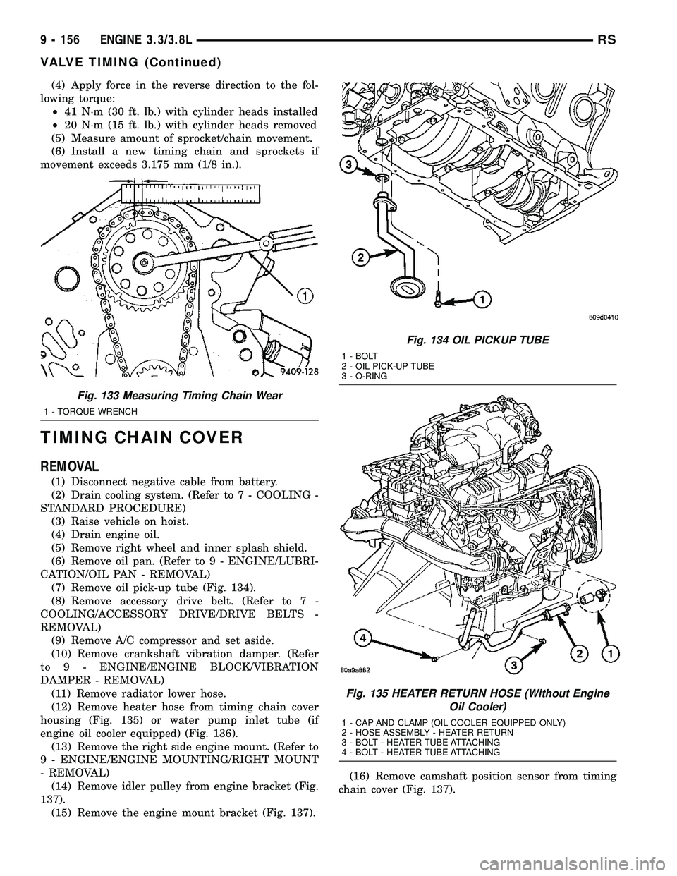
(4) Apply force in the reverse direction to the fol-
lowing torque:
²41 N´m (30 ft. lb.) with cylinder heads installed
²20 N´m (15 ft. lb.) with cylinder heads removed
(5) Measure amount of sprocket/chain movement.
(6) Install a new timing chain and sprockets if
movement exceeds 3.175 mm (1/8 in.).
TIMING CHAIN COVER
REMOVAL
(1) Disconnect negative cable from battery.
(2) Drain cooling system. (Refer to 7 - COOLING -
STANDARD PROCEDURE)
(3) Raise vehicle on hoist.
(4) Drain engine oil.
(5) Remove right wheel and inner splash shield.
(6) Remove oil pan. (Refer to 9 - ENGINE/LUBRI-
CATION/OIL PAN - REMOVAL)
(7) Remove oil pick-up tube (Fig. 134).
(8) Remove accessory drive belt. (Refer to 7 -
COOLING/ACCESSORY DRIVE/DRIVE BELTS -
REMOVAL)
(9) Remove A/C compressor and set aside.
(10) Remove crankshaft vibration damper. (Refer
to 9 - ENGINE/ENGINE BLOCK/VIBRATION
DAMPER - REMOVAL)
(11) Remove radiator lower hose.
(12) Remove heater hose from timing chain cover
housing (Fig. 135) or water pump inlet tube (if
engine oil cooler equipped) (Fig. 136).
(13) Remove the right side engine mount. (Refer to
9 - ENGINE/ENGINE MOUNTING/RIGHT MOUNT
- REMOVAL)
(14) Remove idler pulley from engine bracket (Fig.
137).
(15) Remove the engine mount bracket (Fig. 137).(16) Remove camshaft position sensor from timing
chain cover (Fig. 137).
Fig. 133 Measuring Timing Chain Wear
1 - TORQUE WRENCH
Fig. 134 OIL PICKUP TUBE
1 - BOLT
2 - OIL PICK-UP TUBE
3 - O-RING
Fig. 135 HEATER RETURN HOSE (Without Engine
Oil Cooler)
1 - CAP AND CLAMP (OIL COOLER EQUIPPED ONLY)
2 - HOSE ASSEMBLY - HEATER RETURN
3 - BOLT - HEATER TUBE ATTACHING
4 - BOLT - HEATER TUBE ATTACHING
9 - 156 ENGINE 3.3/3.8LRS
VALVE TIMING (Continued)
Page 1334 of 2339
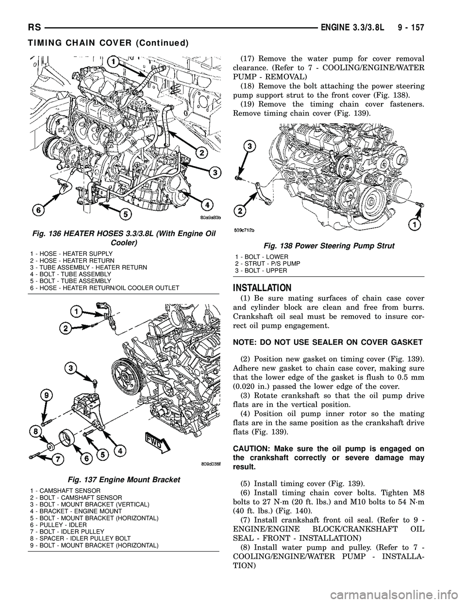
(17) Remove the water pump for cover removal
clearance. (Refer to 7 - COOLING/ENGINE/WATER
PUMP - REMOVAL)
(18) Remove the bolt attaching the power steering
pump support strut to the front cover (Fig. 138).
(19) Remove the timing chain cover fasteners.
Remove timing chain cover (Fig. 139).
INSTALLATION
(1) Be sure mating surfaces of chain case cover
and cylinder block are clean and free from burrs.
Crankshaft oil seal must be removed to insure cor-
rect oil pump engagement.
NOTE: DO NOT USE SEALER ON COVER GASKET
(2) Position new gasket on timing cover (Fig. 139).
Adhere new gasket to chain case cover, making sure
that the lower edge of the gasket is flush to 0.5 mm
(0.020 in.) passed the lower edge of the cover.
(3) Rotate crankshaft so that the oil pump drive
flats are in the vertical position.
(4) Position oil pump inner rotor so the mating
flats are in the same position as the crankshaft drive
flats (Fig. 139).
CAUTION: Make sure the oil pump is engaged on
the crankshaft correctly or severe damage may
result.
(5) Install timing cover (Fig. 139).
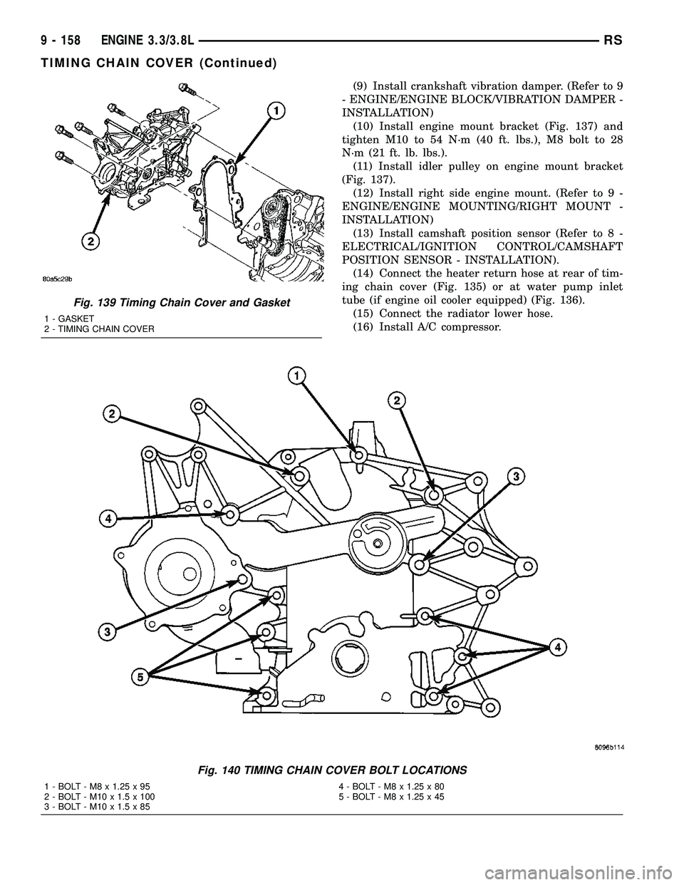
(6) Install timing chain cover bolts. Tighten M8
bolts to 27 N´m (20 ft. lbs.) and M10 bolts to 54 N´m
(40 ft. lbs.) (Fig. 140).
(7) Install crankshaft front oil seal. (Refer to 9 -
ENGINE/ENGINE BLOCK/CRANKSHAFT OIL
SEAL - FRONT - INSTALLATION)
(8) Install water pump and pulley. (Refer to 7 -
COOLING/ENGINE/WATER PUMP - INSTALLA-
TION)
Fig. 136 HEATER HOSES 3.3/3.8L (With Engine Oil
Cooler)
1 - HOSE - HEATER SUPPLY
2 - HOSE - HEATER RETURN
3 - TUBE ASSEMBLY - HEATER RETURN
4 - BOLT - TUBE ASSEMBLY
5 - BOLT - TUBE ASSEMBLY
6 - HOSE - HEATER RETURN/OIL COOLER OUTLET
Fig. 137 Engine Mount Bracket
1 - CAMSHAFT SENSOR
2 - BOLT - CAMSHAFT SENSOR
3 - BOLT - MOUNT BRACKET (VERTICAL)
4 - BRACKET - ENGINE MOUNT
5 - BOLT - MOUNT BRACKET (HORIZONTAL)
6 - PULLEY - IDLER
7 - BOLT - IDLER PULLEY
8 - SPACER - IDLER PULLEY BOLT
9 - BOLT - MOUNT BRACKET (HORIZONTAL)
Fig. 138 Power Steering Pump Strut
1 - BOLT - LOWER
2 - STRUT - P/S PUMP
3 - BOLT - UPPER
RSENGINE 3.3/3.8L9 - 157
TIMING CHAIN COVER (Continued)
Page 1335 of 2339
(9) Install crankshaft vibration damper. (Refer to 9
- ENGINE/ENGINE BLOCK/VIBRATION DAMPER -
INSTALLATION)
(10) Install engine mount bracket (Fig. 137) and
tighten M10 to 54 N´m (40 ft. lbs.), M8 bolt to 28
N´m (21 ft. lb. lbs.).
(11) Install idler pulley on engine mount bracket
(Fig. 137).
(12) Install right side engine mount. (Refer to 9 -
ENGINE/ENGINE MOUNTING/RIGHT MOUNT -
INSTALLATION)
(13) Install camshaft position sensor (Refer to 8 -
ELECTRICAL/IGNITION CONTROL/CAMSHAFT
POSITION SENSOR - INSTALLATION).
(14) Connect the heater return hose at rear of tim-
ing chain cover (Fig. 135) or at water pump inlet
tube (if engine oil cooler equipped) (Fig. 136).
(15) Connect the radiator lower hose.
(16) Install A/C compressor.
Fig. 139 Timing Chain Cover and Gasket
1 - GASKET
2 - TIMING CHAIN COVER
Fig. 140 TIMING CHAIN COVER BOLT LOCATIONS
1 - BOLT - M8 x 1.25 x 95 4 - BOLT - M8 x 1.25 x 80
2 - BOLT - M10 x 1.5 x 100 5 - BOLT - M8 x 1.25 x 45
3 - BOLT - M10 x 1.5 x 85
9 - 158 ENGINE 3.3/3.8LRS
TIMING CHAIN COVER (Continued)
Page 1412 of 2339
CONDITION POSSIBLE CAUSES CORRECTION
SUCKING AIR SOUND 1. Loose clamp on power steering
fluid return hose.1. Tighten or replace hose clamp.
2. Missing O-Ring on power steering
hose connection.2. Inspect connection and replace
O-Ring as required.
3. Low power steering fluid level. 3. Fill power steering fluid reservoir to
proper level and check for leaks.
4. Loose clamp on fluid supply hose. 4. Tighten or replace hose clamp.
SQUEAK OR RUBBING
SOUND1. Steering column shroud rubbing. 1. Realign shrouds as necessary.
2. Steering column shaft rubbing. 2. Move or realign item rubbing shaft.
3. Clockspring noisy. 3. Remove clockspring. Reinstall wheel.
If noise is gone, replace clockspring.
4. Seal lubrication inadequate. 4. Lube seal (if external).
5. Steering gear internally noisy. 5. Replace steering gear (if no other
cause can be found).
SCRUBBING OR
KNOCKING NOISE.1. Incorrect tire or wheel size. 1. Replace incorrect size tire or wheel
with size used as original equipment.
2. Interference between steering
gear and other vehicle components.2. Check for bent or misaligned
components and correct as necessary.
3. Steering gear internal stops worn
excessively allowing tires to be
steered excessively far.3. Replace steering gear.
* NOTE: There is some noise in all power steering
systems. One of the most common is a hissing
sound evident when turning the steering wheel
when at a standstill or when parking and the steer-
ing wheel is at the end of its travel. Hiss is a very
high frequency noise similar to that experienced
while slowly closing a water tap. The noise is
present in every valve and results when high veloc-
ity fluid passes valve orifice edges. There is no
relationship between this noise and the perfor-
mance of the steering system.** NOTE: A light clunk may be felt or heard during
steering wheel reversal while vehicle is stationary.
This results from internal steering gear rack move-
ment at the bushings and in no way affects the per-
formance of the steering system. This movement
may be felt in the steering components during
steering wheel reversal.
*** NOTE: Power steering pump growl/moan/groan
results from the development of high pressure fluid
flow. Normally this noise level should not be high
enough to be objectionable.
RSSTEERING19-5
STEERING (Continued)
Page 1416 of 2339
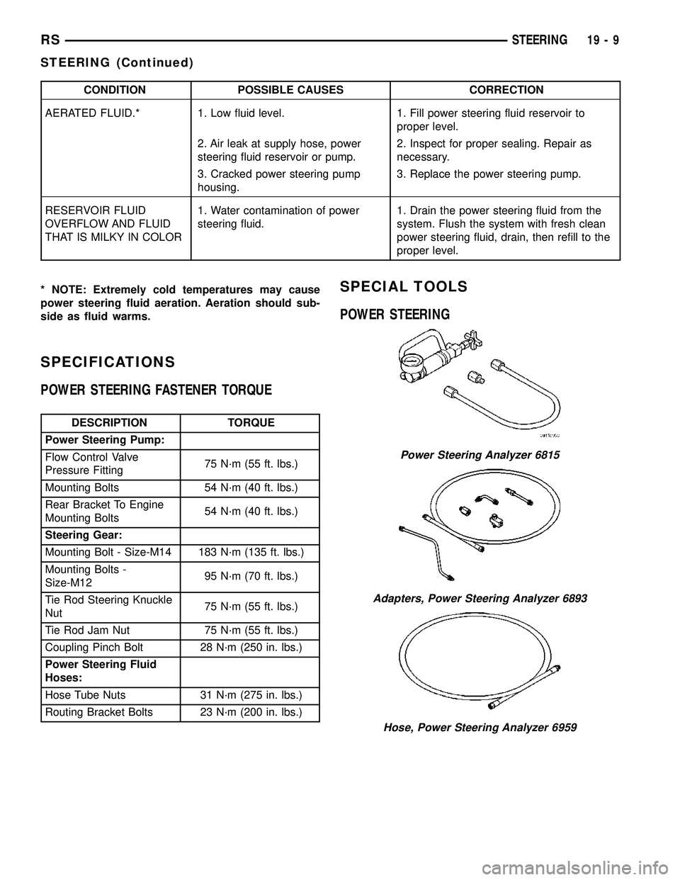
CONDITION POSSIBLE CAUSES CORRECTION
AERATED FLUID.* 1. Low fluid level. 1. Fill power steering fluid reservoir to
proper level.
2. Air leak at supply hose, power
steering fluid reservoir or pump.2. Inspect for proper sealing. Repair as
necessary.
3. Cracked power steering pump
housing.3. Replace the power steering pump.
RESERVOIR FLUID
OVERFLOW AND FLUID
THAT IS MILKY IN COLOR1. Water contamination of power
steering fluid.1. Drain the power steering fluid from the
system. Flush the system with fresh clean
power steering fluid, drain, then refill to the
proper level.
* NOTE: Extremely cold temperatures may cause
power steering fluid aeration. Aeration should sub-
side as fluid warms.
SPECIFICATIONS
POWER STEERING FASTENER TORQUE
DESCRIPTION TORQUE
Power Steering Pump:
Flow Control Valve
Pressure Fitting75 N´m (55 ft. lbs.)
Mounting Bolts 54 N´m (40 ft. lbs.)
Rear Bracket To Engine
Mounting Bolts54 N´m (40 ft. lbs.)
Steering Gear:
Mounting Bolt - Size-M14 183 N´m (135 ft. lbs.)
Mounting Bolts -
Size-M1295 N´m (70 ft. lbs.)
Tie Rod Steering Knuckle
Nut75 N´m (55 ft. lbs.)
Tie Rod Jam Nut 75 N´m (55 ft. lbs.)
Coupling Pinch Bolt 28 N´m (250 in. lbs.)
Power Steering Fluid
Hoses:
Hose Tube Nuts 31 N´m (275 in. lbs.)
Routing Bracket Bolts 23 N´m (200 in. lbs.)
SPECIAL TOOLS
POWER STEERING
Power Steering Analyzer 6815
Adapters, Power Steering Analyzer 6893
Hose, Power Steering Analyzer 6959
RSSTEERING19-9
STEERING (Continued)
Page 1543 of 2339
FLUID
STANDARD PROCEDURE
FLUID LEVEL AND CONDITION CHECK
NOTE: Only transmission fluid of the type labeled
Mopar ATF+4 (Automatic Transmission Fluid)
should be used in this transaxle.
FLUID LEVEL CHECK
The transmission sump has a fluid level indicator
(dipstick) to check oil similar to most automatic
transmissions. It is located on the left side of the
engine. Be sure to wipe all dirt from dipstick handle
before removing.
The torque converter fills in both the P Park and N
Neutral positions. Place the selector lever in P Park
to be sure that the fluid level check is accurate.The
engine should be running at idle speed for at
least one minute, with the vehicle on level
ground.At normal operating temperature 82É C
(180É F), the fluid level is correct if it is in the HOT
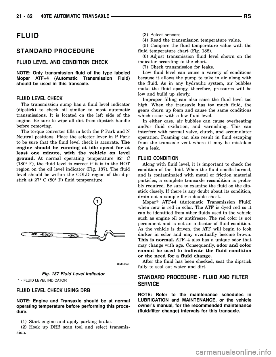
region on the oil level indicator (Fig. 187). The fluid
level should be within the COLD region of the dip-
stick at 27É C (80É F) fluid temperature.
FLUID LEVEL CHECK USING DRB
NOTE: Engine and Transaxle should be at normal
operating temperature before performing this proce-
dure.
(1) Start engine and apply parking brake.
(2) Hook up DRB scan tool and select transmis-
sion.(3) Select sensors.
(4) Read the transmission temperature value.
(5) Compare the fluid temperature value with the
fluid temperature chart (Fig. 188).
(6) Adjust transmission fluid level shown on the
indicator according to the chart.
(7) Check transmission for leaks.
Low fluid level can cause a variety of conditions
because it allows the pump to take in air along with
the fluid. As in any hydraulic system, air bubbles
make the fluid spongy, therefore, pressures will be
low and build up slowly.
Improper filling can also raise the fluid level too
high. When the transaxle has too much fluid, the
gears churn up foam and cause the same conditions
which occur with a low fluid level.
In either case, air bubbles can cause overheating
and/or fluid oxidation, and varnishing. This can
interfere with normal valve, clutch, and accumulator
operation. Foaming can also result in fluid escaping
from the transaxle vent where it may be mistaken
for a leak.
FLUID CONDITION
Along with fluid level, it is important to check the
condition of the fluid. When the fluid smells burned,
and is contaminated with metal or friction material
particles, a complete transaxle recondition is proba-
bly required. Be sure to examine the fluid on the dip-
stick closely. If there is any doubt about its condition,
drain out a sample for a double check.
MopartATF+4 (Automatic Transmission Fluid)
when new is red in color. The ATF is dyed red so it
can be identified from other fluids used in the vehicle
such as engine oil or antifreeze. The red color is not
permanent and is not an indicator of fluid condition.
As the vehicle is driven, the ATF will begin to look
darker in color and may eventually become brown.
This is normal.ATF+4 also has a unique odor that
may change with age. Consequently,odor and color
cannot be used to indicate the fluid condition
or the need for a fluid change.
After the fluid has been checked, seat the dipstick
fully to seal out water and dirt.
STANDARD PROCEDURE - FLUID AND FILTER
SERVICE
NOTE: Refer to the maintenance schedules in
LUBRICATION and MAINTENANCE, or the vehicle
owner's manual, for the recommended maintenance
(fluid/filter change) intervals for this transaxle.
Fig. 187 Fluid Level Indicator
1 - FLUID LEVEL INDICATOR
21 - 82 40TE AUTOMATIC TRANSAXLERS
Page 2318 of 2339
HYDRAULIC CIRCUITS AND VALVES -OPERATION .......................... 5-95
HYDRAULIC LASH ADJUSTER NOISE DIAGNOSIS - DIAGNOSIS AND
TESTING ............................ 9-34
HYDRAULIC LASH ADJUSTERS - INSTALLATION ........................ 9-35
HYDRAULIC LASH ADJUSTERS - REMOVAL ........................... 9-35
HYDRAULIC LIFTERS - DIAGNOSIS AND TESTING ........................... 9-116
HYDRAULIC LIFTERS (CAM IN BLOCK) - DESCRIPTION ....................... 9-116
HYDRAULIC LIFTERS (CAM IN BLOCK) - INSTALLATION ....................... 9-117
HYDRAULIC LIFTERS (CAM IN BLOCK) - REMOVAL .......................... 9-117
HYDRAULIC PRESSURE TESTS - DIAGNOSIS AND TESTING ........21-150,21-6
HYDRAULIC SCHEMATICS, SCHEMATICS AND DIAGRAMS - 4XTE TRANSAXLE ....21-199,
21-54
HYDROSTATIC LOCKED ENGINE, STANDARD PROCEDURE ............9-10,9-87
ICU - ASSEMBLY ..................... 5-106
ICU - DISASSEMBLY ..................5-105
ICU (INTEGRATED CONTROL UNIT) - DESCRIPTION ....................... 5-102
ICU (INTEGRATED CONTROL UNIT) - OPERATION ......................... 5-102
IDENTIFICATION - DESCRIPTION, VEHICLE ............................ 23-1
IDENTIFICATION AND INFORMATION - DESCRIPTION, SECTION ..............8W-01-6
IDLE AIR CONTROL MOTOR - DESCRIPTION ....................... 14-33
IDLE AIR CONTROL MOTOR - INSTALLATION ....................... 14-33
IDLE AIR CONTROL MOTOR - OPERATION ......................... 14-33
IDLE AIR CONTROL MOTOR - REMOVAL . . 14-33
IGNITION COIL - DESCRIPTION ...........8I-6
IGNITION COIL - OPERATION .............8I-6
IGNITION SENSE - PCM INPUT - OPERATION ......................... 8E-14
IGNITION SWITCH - INSTALLATION ......19-19
IGNITION SWITCH - REMOVAL ..........19-17
IGNITION SYSTEM - DESCRIPTION ........8I-1
IGNITION SYSTEM - OPERATION ..........8I-1
IGNITION-OFF DRAW TEST, STANDARD PROCEDURE ........................ 8F-13
ILLUMINATION LAMPS - INSTALLATION, CLUSTER ........................... 8L-21
ILLUMINATION LAMPS - REMOVAL, CLUSTER ........................... 8L-21
IMPACT SENSOR - DESCRIPTION .......8O-18
IMPACT SENSOR - INSTALLATION .......8O-21
IMPACT SENSOR - REMOVAL ...........8O-19
INBOARD - 50/50 BENCH - INSTALLATION, SEAT BELT BUCKLE -
SECOND ROW ....................... 8O-38
INBOARD - 50/50 BENCH - REMOVAL, SEAT BELT BUCKLE - SECOND ROW .....8O-37
INBOARD - INSTALLATION, SEAT BELT BUCKLE - FRONT .................... 8O-35
INBOARD - QUAD BUCKET - INSTALLATION, SEAT BELT BUCKLE -
FIRST ROW ......................... 8O-36
INBOARD - QUAD BUCKET - REMOVAL, SEAT BELT BUCKLE - FIRST ROW .......8O-35
INBOARD - REMOVAL, SEAT BELT BUCKLE - FRONT .................... 8O-35
INDICATOR - DESCRIPTION, PASSENGER AIRBAG DISABLED ................... 8O-33
INDICATOR - INSTALLATION, PASSENGER AIRBAG DISABLED .........8O-34
INDICATOR - OPERATION, PASSENGER AIRBAG DISABLED ................... 8O-33
INDICATOR - REMOVAL, PASSENGER AIRBAG DISABLED ................... 8O-34
INDICATOR LAMP - DESCRIPTION, VTSS/SKIS .......................... 8Q-8
INDICATOR LAMP - OPERATION, VTSS/SKIS .......................... 8Q-8
INDICATORS - DIAGNOSIS AND TESTING, TREAD WEAR ...............22-16
INFLATABLE KNEE - INSTALLATION, BLOCKER ........................... 23-75INFLATABLE KNEE - REMOVAL,
BLOCKER ........................... 23-75
INFLATION PRESSURES - STANDARD PROCEDURE, TIRE ................... 22-16
INFO CENTER - DESCRIPTION, ELECTRONIC VEHICLE .................8M-7
INFO CENTER - OPERATION, ELECTRONIC VEHICLE .................8M-7
INFRARED TEMPERATURE SENSOR - DESCRIPTION ....................... 24-28
INFRARED TEMPERATURE SENSOR - OPERATION ......................... 24-28
INITIAL OPERATION - STANDARD PROCEDURE, POWER STEERING
PUMP ............................. 19-37
INJECTION SYSTEM - OPERATION .......14-22
INJECTOR - DESCRIPTION, FUEL ........14-30
INJECTOR - OPERATION, FUEL ..........14-31
INLET AIR TEMPERATURE SENSOR - DESCRIPTION ....................... 14-34
INLET FILTER - INSTALLATION ..........14-17
INLET FILTER - REMOVAL ..............14-17
INLET HOSE - INSTALLATION, HEATER ....24-87
INLET HOSE - REMOVAL, HEATER .......24-86
INLET TUBE - 2.4L - DESCRIPTION, WATER PUMP ........................ 7-36
INLET TUBE - 2.4L - INSTALLATION, WATER PUMP ........................ 7-36
INLET TUBE - 2.4L - REMOVAL, WATER PUMP .............................. 7-36
INLET TUBE - 3.3/3.8L - INSTALLATION, WATER PUMP ......................... 7-37
INLET TUBE - 3.3/3.8L - REMOVAL, WATER PUMP ........................ 7-37
INNER - INSTALLATION, CV BOOT .........3-7
INNER - REMOVAL, CV BOOT .............3-6
INNER BELT MOLDING - INSTALLATION, FRONT DOOR ...................... 23-168
INNER BELT MOLDING - REMOVAL, FRONT DOOR ...................... 23-168
INPUT - DESCRIPTION, SPEED SENSOR . 21-120, 21-271
INPUT - INSTALLATION, SPEED SENSOR ..................... 21-121,21-272
INPUT - OPERATION, DATA BUS COMMUNICATION RECEIVE - PCM .......8E-14
INPUT - OPERATION, IGNITION SENSE - PCM............................... 8E-14
INPUT - OPERATION, SENSOR RETURN - PCM............................... 8E-14
INPUT - OPERATION, SPEED SENSOR . . . 21-120, 21-271
INPUT - REMOVAL, SPEED SENSOR ....21-121,
21-272
INPUT CLUTCH ASSEMBLY - ASSEMBLY . 21-246, 21-95
INPUT CLUTCH ASSEMBLY - DISASSEMBLY ................. 21-237,21-86
INSERT - FOLD-IN-FLOOR - INSTALLATION, REAR FLOOR TUB
CARPETS ........................... 23-96
INSERT - FOLD-IN-FLOOR - INSTALLATION, SECOND ROW FLOOR
TUB CARPET ........................ 23-98
INSERT - FOLD-IN-FLOOR - REMOVAL, REAR FLOOR TUB CARPETS ............23-95
INSERT - FOLD-IN-FLOOR - REMOVAL, SECOND ROW FLOOR TUB CARPET ......23-98
INSTRUMENT CLUSTER - DESCRIPTION . . . 8J-1
INSTRUMENT CLUSTER - OPERATION .....8J-1
INSTRUMENT PANEL - INSTALLATION, LOWER ............................ 23-73
INSTRUMENT PANEL - REMOVAL, LOWER ............................ 23-73
INSTRUMENT PANEL ANTENNA CABLE - INSTALLATION ....................... 8A-12
INSTRUMENT PANEL ANTENNA CABLE - REMOVAL .......................... 8A-12
INSTRUMENT PANEL ASSEMBLY - INSTALLATION ....................... 23-70
INSTRUMENT PANEL ASSEMBLY - REMOVAL .......................... 23-67
INSTRUMENT PANEL CENTER BEZEL - INSTALLATION ....................... 23-72
INSTRUMENT PANEL CENTER BEZEL - REMOVAL .......................... 23-71
INSTRUMENT PANEL DEMISTER DUCTS - INSTALLATION ..................... 24-54INSTRUMENT PANEL DEMISTER DUCTS
- REMOVAL ......................... 24-54
INSTRUMENT PANEL DUCTS - INSTALLATION ....................... 24-55
INSTRUMENT PANEL DUCTS - REMOVAL . 24-55
INSTRUMENT PANEL OUTLETS, INSTALLATION ....................... 24-45
INSTRUMENT PANEL OUTLETS, REMOVAL .......................... 24-45
INSTRUMENT PANEL RIGHT END CAP - INSTALLATION ....................... 23-72
INSTRUMENT PANEL RIGHT END CAP - REMOVAL .......................... 23-72
INSTRUMENT PANEL TOP COVER - INSTALLATION ....................... 23-72
INSTRUMENT PANEL TOP COVER - REMOVAL .......................... 23-72
INSTRUMENT PANEL TOP PAD ASSEMBLY - INSTALLATION ............23-77
INSTRUMENT PANEL TOP PAD ASSEMBLY - REMOVAL ................23-77
INTAKE MANIFOLD - DESCRIPTION . . 9-147,9-60
INTAKE MANIFOLD - INSTALLATION, LOWER ............................ 9-151
INTAKE MANIFOLD - INSTALLATION, UPPER ............................. 9-149
INTAKE MANIFOLD - LOWER - CLEANING .......................... 9-151
INTAKE MANIFOLD - LOWER - INSPECTION .................... 9-151,9-62
INTAKE MANIFOLD - LOWER - INSTALLATION ........................ 9-62
INTAKE MANIFOLD - LOWER - REMOVAL ....9-62
INTAKE MANIFOLD - REMOVAL, LOWER . . 9-150
INTAKE MANIFOLD - REMOVAL, UPPER . . . 9-148
INTAKE MANIFOLD - UPPER - INSPECTION ......................... 9-61
INTAKE MANIFOLD - UPPER - INSTALLATION ........................ 9-61
INTAKE MANIFOLD - UPPER - REMOVAL . . . 9-60
INTAKE MANIFOLD LEAKS - DIAGNOSIS AND TESTING ................... 9-147,9-60
INTAKE MANIFOLD VACUUM PORT REPAIR - STANDARD PROCEDURE .......9-148
INTAKE PIPE - INSTALLATION, AIR ......24-115
INTAKE PIPE - REMOVAL, AIR .........24-115
INTAKE/EXHAUST VALVES & SEATS - CLEANING ...................... 9-108,9-33
INTAKE/EXHAUST VALVES & SEATS - DESCRIPTION ................... 9-107,9-33
INTAKE/EXHAUST VALVES & SEATS - INSPECTION ........................ 9-108
INTAKE/EXHAUST VALVES & SEATS - INSTALLATION ....................... 9-109
INTAKE/EXHAUST VALVES & SEATS - OPERATION ......................... 9-107
INTAKE/EXHAUST VALVES & SEATS - REMOVAL .......................... 9-108
INTEGRAL ANTENNA - EXPORT - DESCRIPTION, QUARTER GLASS ........8A-13
INTEGRAL ANTENNA - EXPORT - OPERATION, QUARTER GLASS ..........8A-13
INTEGRAL ANTENNA, EXPORT - QUARTER GLASS .................... 8A-13
INTEGRATED POWER MODULE - DESCRIPTION .....................8W -97-1
INTEGRATED POWER MODULE - INSTALLATION ....................8W -97-2
INTEGRATED POWER MODULE - OPERATION .......................8W -97-2
INTEGRATED POWER MODULE - REMOVAL ........................8W -97-2
INTERACTIVE SPEED CONTROL (4 SPEED EATX ONLY) - OPERATION ........8P-2
INTERFACE (PCI) BUS, OPERATION - PROGRAMMABLE COMMUNICATIONS ....14-25
INTERIOR LAMPS, SPECIFICATIONS ......8L-20
INTERLOCK SOLENOID - DESCRIPTION, SHIFT ....................... 21-113,21-264
INTERLOCK SOLENOID - DIAGNOSIS AND TESTING, BRAKE/TRANSMISSION
SHIFT ....................... 21-115,21-266
INTERLOCK SOLENOID - INSTALLATION, SHIFT ....................... 21-116,21-267
INTERLOCK SOLENOID - OPERATION, SHIFT ....................... 21-114,21-265
INTERLOCK SOLENOID - REMOVAL, SHIFT ....................... 21-115,21-266
RS INDEX17
Description Group-Page Description Group-Page Description Group-Page