2005 CHRYSLER CARAVAN remove seats
[x] Cancel search: remove seatsPage 1348 of 2339
FRAME & BUMPERS
TABLE OF CONTENTS
page page
BUMPERS
SPECIFICATIONS - TORQUE...............1
FRONT FASCIA
REMOVAL.............................1
INSTALLATION..........................1
FRONT BUMPER REINFORCEMENT
REMOVAL.............................3
INSTALLATION..........................3
REAR FASCIA
REMOVAL.............................4
INSTALLATION..........................4
REAR BUMPER REINFORCEMENT
REMOVAL.............................5
INSTALLATION..........................5
REAR FASCIA - SCUFF PAD
REMOVAL.............................5
INSTALLATION..........................5FRAME
SPECIFICATIONS
SPECIFICATIONS - FRAME DIMENSIONS . . . 6
SPECIFICATIONS - FRAME DIMENSIONS -
FOLD-IN-FLOOR SEATS ONLY...........11
SPECIFICATIONS - TORQUE............14
FRONT CRADLE CROSSMEMBER
DESCRIPTION
DESCRIPTION - FRONT CRADLE
CROSSMEMBER......................14
DESCRIPTION - FRONT CRADLE
CROSSMEMBER THREAD REPAIR........14
REMOVAL.............................15
INSTALLATION.........................16
FRONT CROSSMEMBER MOUNT BUSHINGS
REMOVAL.............................17
INSTALLATION.........................17
BUMPERS
SPECIFICATIONS - TORQUE
DESCRIPTION N´m Ft. Lbs. In. Lbs.
Front bumper reinforcement attaching nut 54 40 Ð
Rear bumper reinforcement attaching nut 27 20 Ð
FRONT FASCIA
REMOVAL
(1) Release hood latch and open hood.
(2) Remove the headlamp assemblies (Refer to 8 -
ELECTRICAL/LAMPS/LIGHTING - EXTERIOR/
HEADLAMP - REMOVAL).
(3) Hoist vehicle and support with safety stands.
(4) Remove the five push pin fasteners attaching
bottom of fascia/air dam to radiator closure panel.
(5) Remove front wheels.
(6) Remove front wheelhouse splash shields fasten-
ers as necessary to gain access to bolts attaching
front fascia to fender. (Refer to 23 - BODY/EXTERI-
OR/ WHEELHOUSE SPLASH SHIELD -
REMOVAL).(7) Remove the two bolts and two nuts attaching
fascia to the front fenders (Fig. 1) and (Fig. 2).
(8) Disconnect fog lamp wire connectors, if neces-
sary.
(9) Lower vehicle.
(10) Remove two bolts attaching the upper grille
support to the headlamp mounting panel at each side
of the grille.
(11) Remove bumper fascia from vehicle.
INSTALLATION
(1) Position front bumper fascia on vehicle (Fig. 1)
and (Fig. 2).
(2) Install the two bolts attaching fascia to head-
lamp mounting panel at each side of grille.
(3) Hoist vehicle and support with safety stands.
RSFRAME & BUMPERS13-1
Page 1780 of 2339
BODY
TABLE OF CONTENTS
page page
BODY
DESCRIPTION - VEHICLE IDENTIFICATION....1
WARNING
SAFETY PRECAUTIONS AND WARNINGS . . . 1
DIAGNOSIS AND TESTING
WATER LEAKS........................1
WIND NOISE..........................2
STANDARD PROCEDURE
STANDARD PROCEDURE - PLASTIC BODY
PANEL REPAIR........................3
STANDARD PROCEDURE - HEAT STAKING . . 9
SPECIFICATIONS
TORQUE............................10
BODY LUBRICATION...................12
SPECIAL TOOLS
BODY..............................13DOOR - FRONT.........................14
DOORS - SLIDING.......................24
DECKLID/HATCH/LIFTGATE/TAILGATE.......40
EXTERIOR.............................45
HOOD.................................62
INSTRUMENT PANEL.....................65
INTERIOR..............................78
PAINT................................100
SEATS...............................102
STATIONARY GLASS....................161
WEATHERSTRIP/SEALS..................166
SUNROOF.............................169
BODY STRUCTURE.....................177
BODY
DESCRIPTION - VEHICLE IDENTIFICATION
Throughout this group, references to the
DaimlerChrysler Corporation vehicle family identifi-
cation code are used when describing a procedure
that is unique to that vehicle. Refer to Introduction
Group of this manual for detailed information on
vehicle identification. If a procedure is common to all
vehicles covered in this manual, no reference will be
made to a vehicle family code.
WARNING
SAFETY PRECAUTIONS AND WARNINGS
WARNING: USE A OSHA APPROVED BREATHING
FILTER WHEN SPRAYING PAINT OR SOLVENTS IN
A CONFINED AREA. PERSONAL INJURY CAN
RESULT.
AVOID PROLONGED SKIN CONTACT WITH PETRO-
LEUM OR ALCOHOL ± BASED CLEANING SOL-
VENTS. PERSONAL INJURY CAN RESULT.
DO NOT STAND UNDER A HOISTED VEHICLE THAT
IS NOT PROPERLY SUPPORTED ON SAFETY
STANDS. PERSONAL INJURY CAN RESULT.
CAUTION: When holes must be drilled or punched
in an inner body panel, verify depth of space to the
outer body panel, electrical wiring, or other compo-nents. Damage to vehicle can result.
Do not weld exterior panels unless combustible
material on the interior of vehicle is removed from
the repair area. Fire or hazardous conditions, can
result.
Always have a fire extinguisher ready for use when
welding.
Disconnect the negative (-) cable clamp from the
battery when servicing electrical components that
are live when the ignition is OFF. Damage to electri-
cal system can result.
Do not use abrasive chemicals or compounds on
painted surfaces. Damage to finish can result.
Do not use harsh alkaline based cleaning solvents
on painted or upholstered surfaces. Damage to fin-
ish or color can result.
Do not hammer or pound on plastic trim panel
when servicing interior trim. Plastic panels can
break.
DIAGNOSIS AND TESTING
WATER LEAKS
Water leaks can be caused by poor sealing,
improper body component alignment, body seam
porosity, missing plugs, or blocked drain holes. Cen-
trifugal and gravitational force can cause water to
drip from a location away from the actual leak point,
making leak detection difficult. All body sealing
points should be water tight in normal wet-driving
conditions. Water flowing downward from the front of
RSBODY23-1
Page 1860 of 2339
CARPETS AND FLOOR MATS
REMOVAL
(1) Remove front seats. (Refer to 23 - BODY/
SEATS/SEAT - REMOVAL)
(2) Remove front center console.
(3) Remove heel blocker (plastic block below accel-
erator pedal).
(4) Remove the remaining seats. Refer to the Own-
er's Manual for the proper procedures.
(5) Remove front cowl panels and sill plates.
(6) Remove sliding door sill plates. (Refer to 23 -
BODY/INTERIOR/SLIDING DOOR SILL PLATE -
REMOVAL)
(7) Remove the cargo organizer, if equipped.
(8) Remove liftgate scuff plate. (Refer to 23 -
BODY/INTERIOR/LIFTGATE SCUFF PLATE -
REMOVAL)
(9) Remove lower B-pillar trim covers.
(10) Remove D-pillar trim covers.
(11) Remove Quarter trim panels.
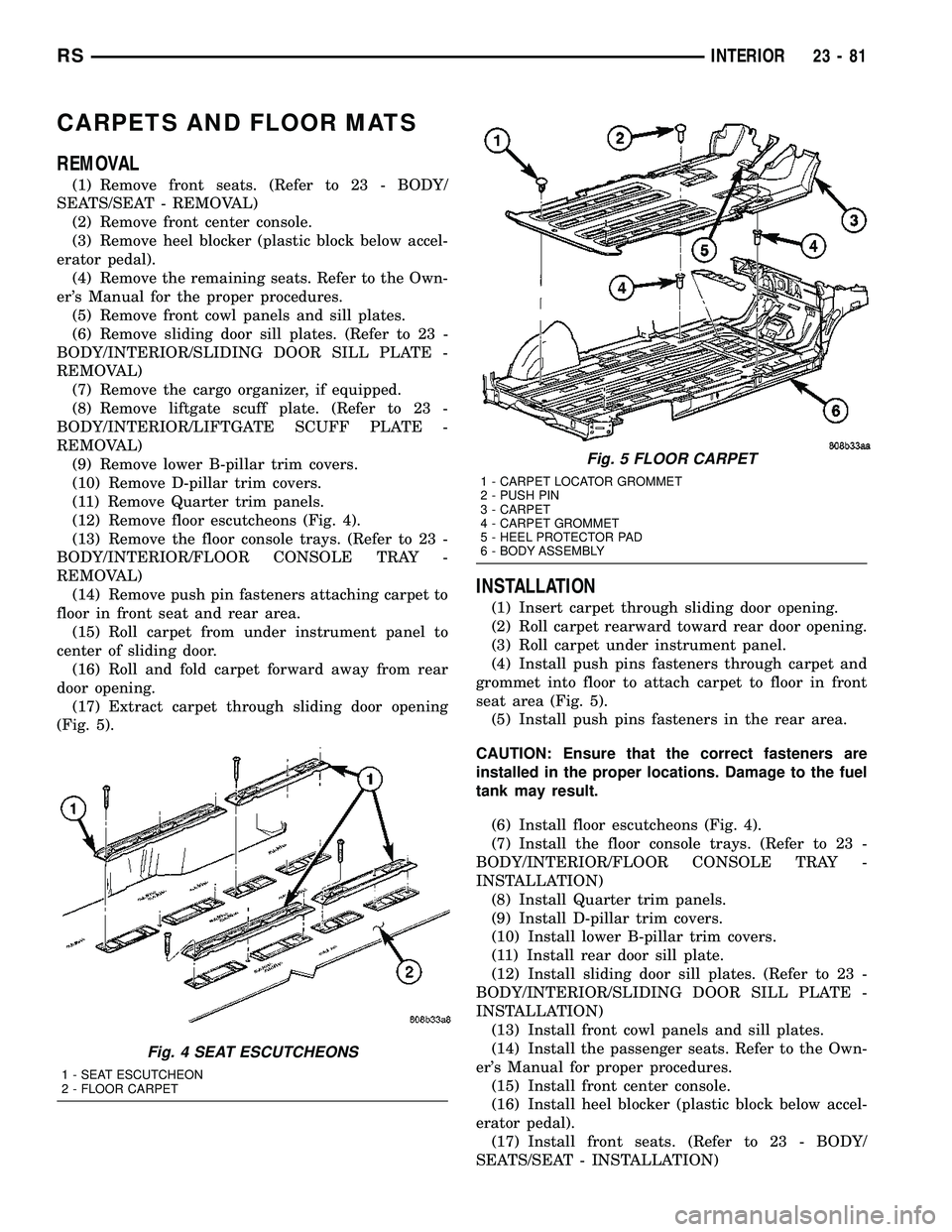
(12) Remove floor escutcheons (Fig. 4).
(13) Remove the floor console trays. (Refer to 23 -
BODY/INTERIOR/FLOOR CONSOLE TRAY -
REMOVAL)
(14) Remove push pin fasteners attaching carpet to
floor in front seat and rear area.
(15) Roll carpet from under instrument panel to
center of sliding door.
(16) Roll and fold carpet forward away from rear
door opening.
(17) Extract carpet through sliding door opening
(Fig. 5).
INSTALLATION
(1) Insert carpet through sliding door opening.
(2) Roll carpet rearward toward rear door opening.
(3) Roll carpet under instrument panel.
(4) Install push pins fasteners through carpet and
grommet into floor to attach carpet to floor in front
seat area (Fig. 5).
(5) Install push pins fasteners in the rear area.
CAUTION: Ensure that the correct fasteners are
installed in the proper locations. Damage to the fuel
tank may result.
(6) Install floor escutcheons (Fig. 4).
(7) Install the floor console trays. (Refer to 23 -
BODY/INTERIOR/FLOOR CONSOLE TRAY -
INSTALLATION)
(8) Install Quarter trim panels.
(9) Install D-pillar trim covers.
(10) Install lower B-pillar trim covers.
(11) Install rear door sill plate.
(12) Install sliding door sill plates. (Refer to 23 -
BODY/INTERIOR/SLIDING DOOR SILL PLATE -
INSTALLATION)
(13) Install front cowl panels and sill plates.
(14) Install the passenger seats. Refer to the Own-
er's Manual for proper procedures.
(15) Install front center console.
(16) Install heel blocker (plastic block below accel-
erator pedal).
(17) Install front seats. (Refer to 23 - BODY/
SEATS/SEAT - INSTALLATION)
Fig. 4 SEAT ESCUTCHEONS
1 - SEAT ESCUTCHEON
2 - FLOOR CARPET
Fig. 5 FLOOR CARPET
1 - CARPET LOCATOR GROMMET
2 - PUSH PIN
3 - CARPET
4 - CARPET GROMMET
5 - HEEL PROTECTOR PAD
6 - BODY ASSEMBLY
RSINTERIOR23-81
Page 1861 of 2339
CARPETS - FOLD-IN-FLOOR
REMOVAL
(1) Remove floor mats.
(2) Remove front seats. (Refer to 23 - BODY/
SEATS/SEAT - REMOVAL)
(3) Remove instrument panel lower console. (Refer
to 23 - BODY/INSTRUMENT PANEL/STORAGE
BIN - REMOVAL).
(4) Remove the floor console base tray and discon-
nect wire connector from the base tray.(Refer to 23 -
BODY/INTERIOR/FLOOR CONSOLE BASE TRAY -
REMOVAL)
(5) Remove heel blocker (plastic block below accel-
erator pedal).
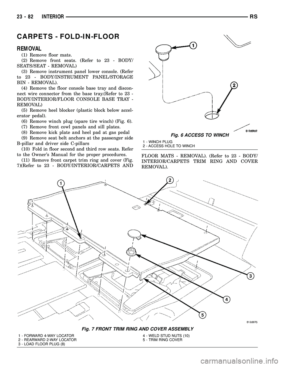
(6) Remove winch plug (spare tire winch) (Fig. 6).
(7) Remove front cowl panels and sill plates.
(8) Remove kick plate and heel pad at gas pedal
(9) Remove seat belt anchors at the passenger side
B-pillar and driver side C-pillars
(10) Fold in floor second and third row seats. Refer
to the Owner's Manual for the proper procedures.
(11) Remove front carpet trim ring and cover (Fig.
7)(Refer to 23 - BODY/INTERIOR/CARPETS ANDFLOOR MATS - REMOVAL). (Refer to 23 - BODY/
INTERIOR/CARPETS TRIM RING AND COVER
REMOVAL).
Fig. 6 ACCESS TO WINCH
1 - WINCH PLUG
2 - ACCESS HOLE TO WINCH
Fig. 7 FRONT TRIM RING AND COVER ASSEMBLY
1 - FORWARD 4-WAY LOCATOR
2 - REARWARD 2-WAY LOCATOR
3 - LOAD FLOOR PLUG (8)4 - WELD STUD NUTS (10)
5 - TRIM RING COVER
23 - 82 INTERIORRS
Page 1863 of 2339
(3) Roll carpet forward under instrument panel
(Fig. 8).
(4) Install push pins fasteners through carpet and
grommet into floor to attach carpet to floor in front
seat area.
(5) Pull wire harnesses through the carpet as
needed.
(6) Smooth out the carpet and allowing weld studs
to go all the way through the carpet.
(7) Install rear push pins fasteners attaching rear
of carpet.
(8) Place third row carpet cover into position and
press clips into position (Fig. 9).
(9) Slide the carpet under the quarter trim panel
into position.
(10) Install lower B-pillar trim covers.
(11) Install sliding door sill plates. (Refer to 23 -
BODY/INTERIOR/SLIDING DOOR SILL PLATE -
INSTALLATION).
(12) Install front carpet trim ring and cover (Fig.
7). (Refer to 23 - BODY/INTERIOR/CARPETS TRIM
RING AND COVER - INSTALLATION)
(13) Install seat belt anchors at the passenger side
B-pillar and driver side C-pillars
(14) Install kick plate and heel pad at the gas
pedal
(15) Install winch plug (spare tire winch) (Fig. 6).
(16) Install front cowl panels and sill plates.
(17) Install heel blocker (plastic block below accel-
erator pedal).
(18) Install the floor console base tray and discon-
nect wire connector from the base tray. (Refer to 23 -
BODY/INTERIOR/FLOOR CONSOLE BASE TRAY -
INSTALLATION).
(19) Install instrument panel lower console. (Refer
to 23 - BODY/INSTRUMENT PANEL/STORAGE
BIN - INSTALLATION).
(20) Install front seats. (Refer to 23 - BODY/
SEATS/SEAT - REMOVAL).
(21) Install floor mats.CARPET TRIM RING AND
COVER - FOLD-IN-FLOOR
REMOVAL
(1) Move front seats to the full forward position.
(2) Fold the second row seats into the floor.
(3) Remove the load floor plugs (Fig. 10).
(4) Remove the ten weld nuts.
(5) Open door covers (Fig. 11).
(6) Remove the four inter weld nuts (Fig. 12).
(7) Raise the front trim ring and cover up off of
the weld studs and remove from vehicle.
INSTALLATION
(1) Place front trim ring and cover assembly into
position.
(2) Open door covers (Fig. 11).
(3) Install the four inter weld nuts (Fig. 12).
(4) Close door covers.
(5) Install the ten weld nuts (Fig. 10).
(6) Install the eight load floor plugs.
(7) Open the second row seats into position.
(8) Move front seats to the position.
23 - 84 INTERIORRS
CARPETS - FOLD-IN-FLOOR (Continued)
Page 1874 of 2339
INSTALLATION
(1) Place sill plate in position on vehicle.
(2) Align engage hook tabs at end of liftgate sill
plate to D-pillar trim.
(3) Engage hidden clips to hold sill plate to liftgate
door opening sill.
QUARTER TRIM BOLSTER
REMOVAL
The speaker grille in the quarter trim panel is not
removable. The trim panel must be removed to ser-
vice the speaker.
(1) Disengage hidden clips attaching trim bolster
to quarter trim panel.
(2) Remove quarter trim panel from vehicle.
INSTALLATION
The speaker grille in the quarter trim bolster is
not removable. The trim bolster must removed to ser-
vice the speaker.
(1) Place quarter trim bolster in position on vehi-
cle.
(2) Engage hook retainer attaching front of trim
bolster to quarter trim panel, if applicable.
(3) Engage hidden clips attaching trim bolster to
quarter trim panel.
REAR FLOOR TUB CARPETS
INSERT - FOLD-IN-FLOOR
REMOVAL
(1) Open liftgate.
(2) Remove liftgate sill plate. (Refer to 23 - BODY/
INTERIOR/LIFTGATE SILL PLATE - REMOVAL).
(3) Fold third row seats in to floor well.
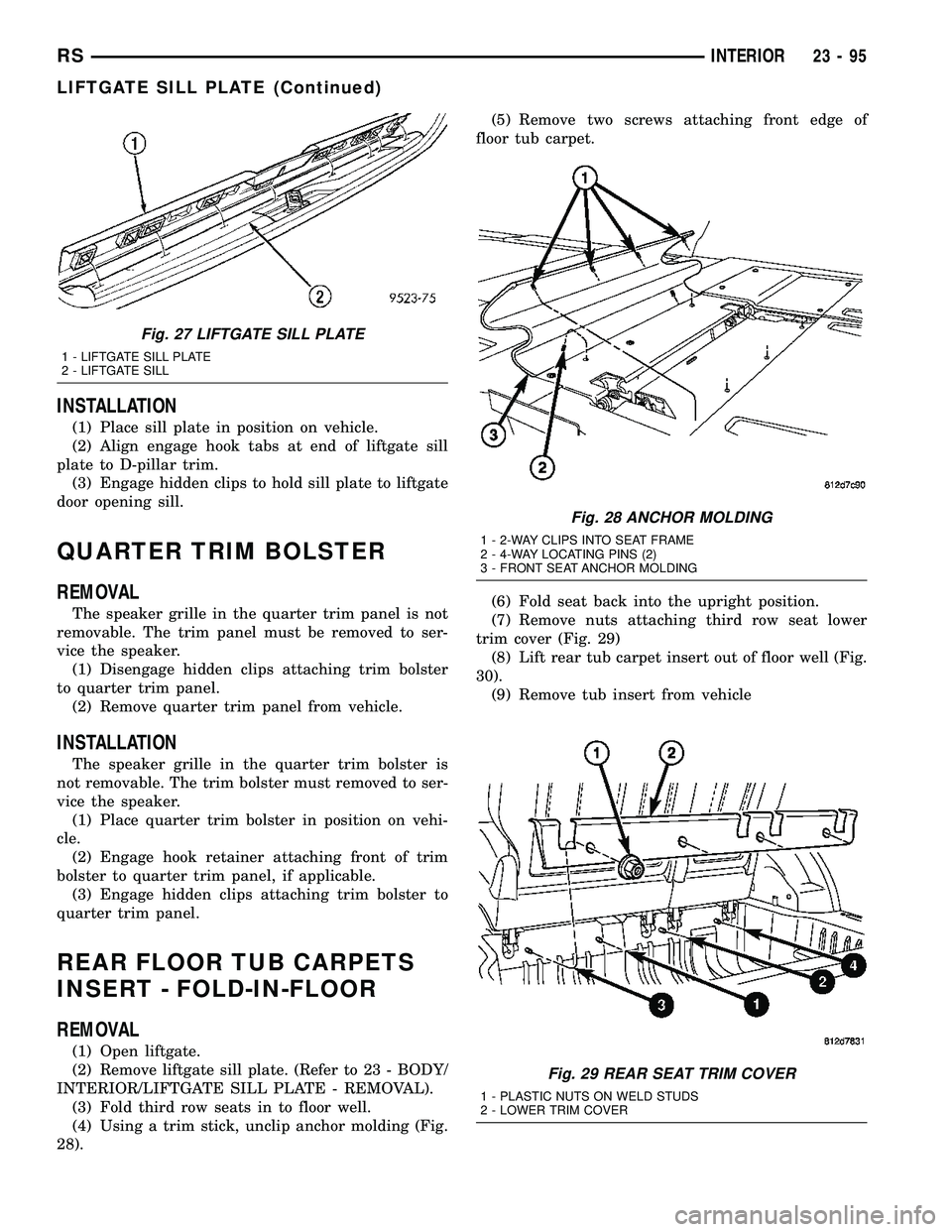
(4) Using a trim stick, unclip anchor molding (Fig.
28).(5) Remove two screws attaching front edge of
floor tub carpet.
(6) Fold seat back into the upright position.
(7) Remove nuts attaching third row seat lower
trim cover (Fig. 29)
(8) Lift rear tub carpet insert out of floor well (Fig.
30).
(9) Remove tub insert from vehicle
Fig. 27 LIFTGATE SILL PLATE
1 - LIFTGATE SILL PLATE
2 - LIFTGATE SILL
Fig. 28 ANCHOR MOLDING
1 - 2-WAY CLIPS INTO SEAT FRAME
2 - 4-WAY LOCATING PINS (2)
3 - FRONT SEAT ANCHOR MOLDING
Fig. 29 REAR SEAT TRIM COVER
1 - PLASTIC NUTS ON WELD STUDS
2 - LOWER TRIM COVER
RSINTERIOR23-95
LIFTGATE SILL PLATE (Continued)
Page 1875 of 2339

INSTALLATION
(1) Place rear tub carpet insert into position on
weld studs (Fig. 30).
(2) Slip carpet edges under quarter trim panel.
(3) Install nuts attaching third row seat lower trim
cover (Fig. 29). Follow the tightening sequence.
(4) Fold third row seats in to floor well.
(5) Install two screws attaching front edge of floor
tub carpet.
(6) Place anchor molding into position push on
clips to lock (Fig. 28).
(7) Remove liftgate sill plate. (Refer to 23 - BODY/
INTERIOR/LIFTGATE SILL PLATE - INSTALLA-
TION).
(8) Close liftgate.
REAR HEADER TRIM
REMOVAL
(1) Disengage hidden clips holding trim to rear
header (Fig. 31).
(2) Separate rear header trim from vehicle.
INSTALLATION
(1) Place rear header trim in position on vehicle.
(2) Align guide pins on trim to holes in header.
(3) Engage hidden clips to hold trim to rear
header.
(4) Engage interlock tabs at D-pillar trim.
REAR HVAC LOUVER
REMOVAL
(1) Using a trim stick (C-4755), pry edge of louver
from bezel.
(2) Remove HVAC louver from bezel.
(3) Using a trim stick, pry lower edge of HVAC
bezel away from headlining (Fig. 32).
(4) Remove louver from vehicle.
Fig. 30 REAR FLOOR TUB CARPET INSERT
1 - REAR TUB
2- TAB ON SIDE OF CARPET IN WHEELHOUSE AREA
3 - REAR TUB CARPET
4 - LOAD THROUGH LIFTGATE OPENING
Fig. 31 REAR HEADER TRIM
1 - REAR HEADER
2 - GUIDE PINS
3 - CLIPS
Fig. 32 REAR HVAC LOUVER
1 - HEVAC DUCT
2 - REAR HEVAC LOUVER
3 - HEADLINING
4 - CLIP
23 - 96 INTERIORRS
REAR FLOOR TUB CARPETS INSERT - FOLD-IN-FLOOR (Continued)
Page 1877 of 2339
(4) Remove bolt attaching second row seat belt,
anchor to quarter on short wheel base vehicle.
(5)
Disengage hidden clips attaching trim to D-pillar.
(6) Remove D-pillar trim panel from D-pillar.
(7) Disconnect speaker wire connector, if equipped.
(8) Pass second row seat belt, if equipped, through
slot in trim panel on short wheel base vehicle.
(9) Remove D-pillar trim from vehicle.
INSTALLATION
(1) Position D-pillar trim on vehicle.
(2) Pass second row seat belt, if equipped, through
slot in trim panel on short wheel base vehicle.
(3) Connect speaker wire connector to speaker, if
equipped.
(4) Align locating pins on backside of trim panel to
mating holes in D-pillar.
(5) Engage hidden clips attaching trim to D-pillar.
(6) Install screws attaching trim panel to attach-
ing bracket on short wheel base vehicle.
(7) Install quarter trim bolster on short wheel base
vehicle.
(8) Install bolt to attach second row seat belt, if
equipped, anchor to quarter on short wheel base
vehicle. Tighten all seat belt bolts to 39 N´m (29 ft.
lbs.) torque.
(9) Install second row seat belt turning loop on
long wheel base vehicle.
(10) Install liftgate sill plate.
(11) Install rear header trim cover.
SECOND ROW FLOOR TUB
CARPET INSERT - FOLD-IN-
FLOOR
REMOVAL
(1) Move both front seats to the full forward posi-
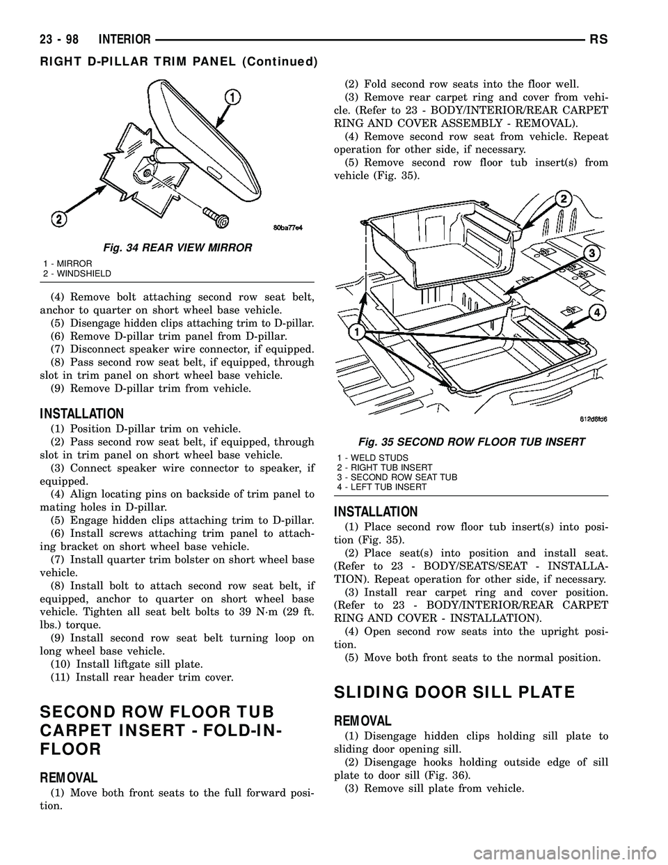
tion.(2) Fold second row seats into the floor well.
(3) Remove rear carpet ring and cover from vehi-
cle. (Refer to 23 - BODY/INTERIOR/REAR CARPET
RING AND COVER ASSEMBLY - REMOVAL).
(4) Remove second row seat from vehicle. Repeat
operation for other side, if necessary.
(5) Remove second row floor tub insert(s) from
vehicle (Fig. 35).
INSTALLATION
(1) Place second row floor tub insert(s) into posi-
tion (Fig. 35).
(2) Place seat(s) into position and install seat.
(Refer to 23 - BODY/SEATS/SEAT - INSTALLA-
TION). Repeat operation for other side, if necessary.
(3) Install rear carpet ring and cover position.
(Refer to 23 - BODY/INTERIOR/REAR CARPET
RING AND COVER - INSTALLATION).
(4) Open second row seats into the upright posi-
tion.
(5) Move both front seats to the normal position.
SLIDING DOOR SILL PLATE
REMOVAL
(1) Disengage hidden clips holding sill plate to
sliding door opening sill.
(2) Disengage hooks holding outside edge of sill
plate to door sill (Fig. 36).
(3) Remove sill plate from vehicle.
Fig. 34 REAR VIEW MIRROR
1 - MIRROR
2 - WINDSHIELD
Fig. 35 SECOND ROW FLOOR TUB INSERT
1 - WELD STUDS
2 - RIGHT TUB INSERT
3 - SECOND ROW SEAT TUB
4 - LEFT TUB INSERT
23 - 98 INTERIORRS
RIGHT D-PILLAR TRIM PANEL (Continued)