2005 CHRYSLER CARAVAN torque
[x] Cancel search: torquePage 1843 of 2339
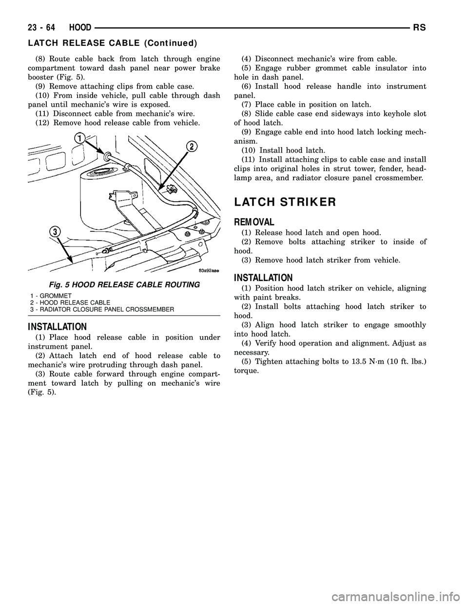
(8) Route cable back from latch through engine
compartment toward dash panel near power brake
booster (Fig. 5).
(9) Remove attaching clips from cable case.
(10) From inside vehicle, pull cable through dash
panel until mechanic's wire is exposed.
(11) Disconnect cable from mechanic's wire.
(12) Remove hood release cable from vehicle.
INSTALLATION
(1) Place hood release cable in position under
instrument panel.
(2) Attach latch end of hood release cable to
mechanic's wire protruding through dash panel.
(3) Route cable forward through engine compart-
ment toward latch by pulling on mechanic's wire
(Fig. 5).(4) Disconnect mechanic's wire from cable.
(5) Engage rubber grommet cable insulator into
hole in dash panel.
(6) Install hood release handle into instrument
panel.
(7) Place cable in position on latch.
(8) Slide cable case end sideways into keyhole slot
of hood latch.
(9) Engage cable end into hood latch locking mech-
anism.
(10) Install hood latch.
(11) Install attaching clips to cable case and install
clips into original holes in strut tower, fender, head-
lamp area, and radiator closure panel crossmember.
LATCH STRIKER
REMOVAL
(1) Release hood latch and open hood.
(2) Remove bolts attaching striker to inside of
hood.
(3) Remove hood latch striker from vehicle.
INSTALLATION
(1) Position hood latch striker on vehicle, aligning
with paint breaks.
(2) Install bolts attaching hood latch striker to
hood.
(3) Align hood latch striker to engage smoothly
into hood latch.
(4) Verify hood operation and alignment. Adjust as
necessary.
(5) Tighten attaching bolts to 13.5 N´m (10 ft. lbs.)
torque.Fig. 5 HOOD RELEASE CABLE ROUTING
1 - GROMMET
2 - HOOD RELEASE CABLE
3 - RADIATOR CLOSURE PANEL CROSSMEMBER
23 - 64 HOODRS
LATCH RELEASE CABLE (Continued)
Page 1859 of 2339
(1) Slide lower seat belt cover rearward to expose
anchor fastener.
(2) Remove bolt/nut attaching lower seat belt
anchor to floor.
(3) Remove upper B-pillar trim cover.
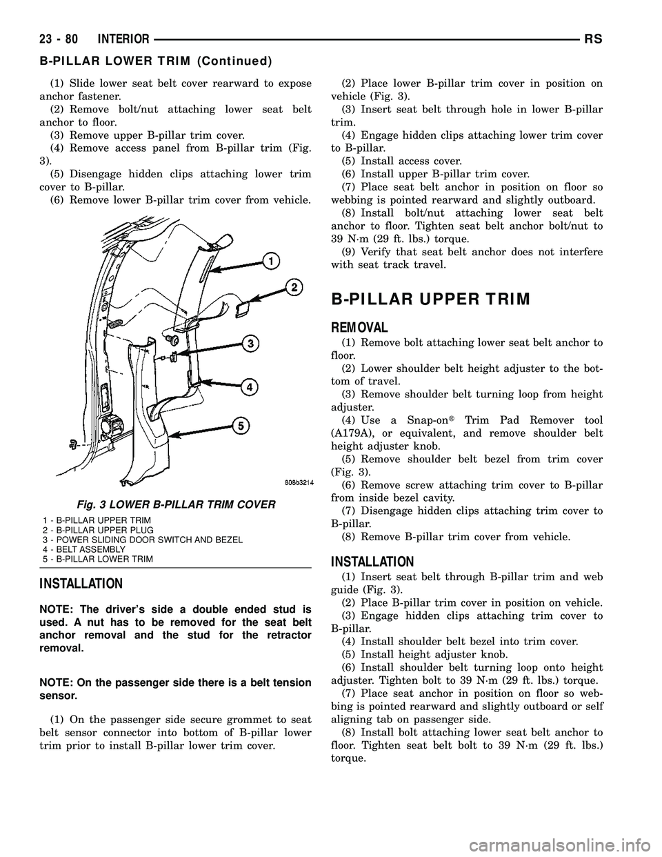
(4) Remove access panel from B-pillar trim (Fig.
3).
(5) Disengage hidden clips attaching lower trim
cover to B-pillar.
(6) Remove lower B-pillar trim cover from vehicle.
INSTALLATION
NOTE: The driver's side a double ended stud is
used. A nut has to be removed for the seat belt
anchor removal and the stud for the retractor
removal.
NOTE: On the passenger side there is a belt tension
sensor.
(1) On the passenger side secure grommet to seat
belt sensor connector into bottom of B-pillar lower
trim prior to install B-pillar lower trim cover.(2) Place lower B-pillar trim cover in position on
vehicle (Fig. 3).
(3) Insert seat belt through hole in lower B-pillar
trim.
(4) Engage hidden clips attaching lower trim cover
to B-pillar.
(5) Install access cover.
(6) Install upper B-pillar trim cover.
(7) Place seat belt anchor in position on floor so
webbing is pointed rearward and slightly outboard.
(8) Install bolt/nut attaching lower seat belt
anchor to floor. Tighten seat belt anchor bolt/nut to
39 N´m (29 ft. lbs.) torque.
(9) Verify that seat belt anchor does not interfere
with seat track travel.
B-PILLAR UPPER TRIM
REMOVAL
(1) Remove bolt attaching lower seat belt anchor to
floor.
(2) Lower shoulder belt height adjuster to the bot-
tom of travel.
(3) Remove shoulder belt turning loop from height
adjuster.
(4) Use a Snap-ontTrim Pad Remover tool
(A179A), or equivalent, and remove shoulder belt
height adjuster knob.
(5) Remove shoulder belt bezel from trim cover
(Fig. 3).
(6) Remove screw attaching trim cover to B-pillar
from inside bezel cavity.
(7) Disengage hidden clips attaching trim cover to
B-pillar.
(8) Remove B-pillar trim cover from vehicle.
INSTALLATION
(1) Insert seat belt through B-pillar trim and web
guide (Fig. 3).
(2) Place B-pillar trim cover in position on vehicle.
(3) Engage hidden clips attaching trim cover to
B-pillar.
(4) Install shoulder belt bezel into trim cover.
(5) Install height adjuster knob.
(6) Install shoulder belt turning loop onto height
adjuster. Tighten bolt to 39 N´m (29 ft. lbs.) torque.
(7) Place seat anchor in position on floor so web-
bing is pointed rearward and slightly outboard or self
aligning tab on passenger side.
(8) Install bolt attaching lower seat belt anchor to
floor. Tighten seat belt bolt to 39 N´m (29 ft. lbs.)
torque.
Fig. 3 LOWER B-PILLAR TRIM COVER
1 - B-PILLAR UPPER TRIM
2 - B-PILLAR UPPER PLUG
3 - POWER SLIDING DOOR SWITCH AND BEZEL
4 - BELT ASSEMBLY
5 - B-PILLAR LOWER TRIM
23 - 80 INTERIORRS
B-PILLAR LOWER TRIM (Continued)
Page 1867 of 2339
COWL TRIM
REMOVAL
(1) Remove door sill plate.
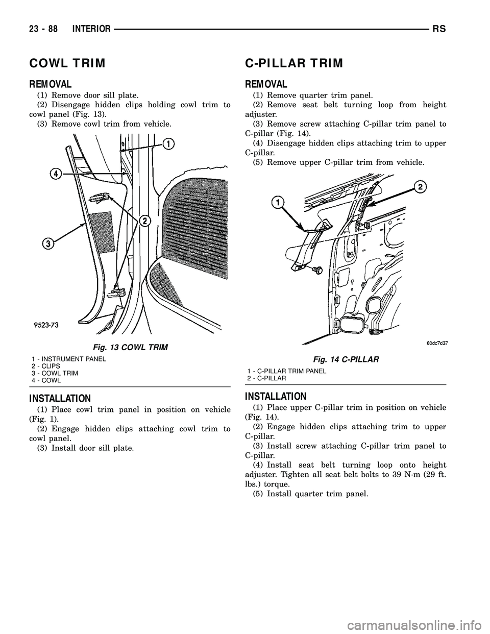
(2) Disengage hidden clips holding cowl trim to
cowl panel (Fig. 13).
(3) Remove cowl trim from vehicle.
INSTALLATION
(1) Place cowl trim panel in position on vehicle
(Fig. 1).
(2) Engage hidden clips attaching cowl trim to
cowl panel.
(3) Install door sill plate.
C-PILLAR TRIM
REMOVAL
(1) Remove quarter trim panel.
(2) Remove seat belt turning loop from height
adjuster.
(3) Remove screw attaching C-pillar trim panel to
C-pillar (Fig. 14).
(4) Disengage hidden clips attaching trim to upper
C-pillar.
(5) Remove upper C-pillar trim from vehicle.
INSTALLATION
(1) Place upper C-pillar trim in position on vehicle
(Fig. 14).
(2) Engage hidden clips attaching trim to upper
C-pillar.
(3) Install screw attaching C-pillar trim panel to
C-pillar.
(4) Install seat belt turning loop onto height
adjuster. Tighten all seat belt bolts to 39 N´m (29 ft.
lbs.) torque.
(5) Install quarter trim panel.
Fig. 13 COWL TRIM
1 - INSTRUMENT PANEL
2 - CLIPS
3 - COWL TRIM
4 - COWLFig. 14 C-PILLAR
1 - C-PILLAR TRIM PANEL
2 - C-PILLAR
23 - 88 INTERIORRS
Page 1873 of 2339
LEFT D-PILLAR TRIM PANEL
REMOVAL
(1) Remove rear header trim cover.
(2) Remove liftgate sill plate.
(3) Remove second row seat belt turning loop on
long wheel base vehicle.
(4) Remove bolt attaching second row seat belt
lower anchor to quarter on short wheel base vehicle.
(5) Disengage hidden clips attaching trim to D-pil-
lar.
(6) Disconnect speaker wire connector, if equipped.
(7) Pass seat belt through slot in D-pillar trim
panel on short wheel base vehicle.
(8) Remove D-pillar trim from vehicle.
INSTALLATION
(1) Pass seat belt through slot in D-pillar trim
panel on short wheel base vehicle.
(2) Position D-pillar trim panel on vehicle.
(3) Connect speaker wire connector to speaker, if
equipped.
(4) Align locating pins on backside of trim panel to
mating holes in inner quarter panel.
(5) Engage hidden clips attaching trim to D-pillar.
(6) Install bolt attaching second row seat belt
lower anchor to quarter on short wheel base vehicle.
Tighten all seat belt bolts to 39 N´m (29 ft. lbs.).
(7) Install second row seat belt turning loop on
long wheel base vehicle.
(8) Install liftgate sill plate.
(9) Install rear header trim cover.
LEFT QUARTER TRIM PANEL
REMOVAL
CAUTION: Disconnect the negative cable clamp
from battery post. Damage to accessory feed circuit
can result.
(1) Remove first row seat.
(2) Remove second row seat, if equipped.
(3) Remove front door sill plate on three door vehi-
cle.
(4) Remove sliding door sill plate on four door
vehicle.
(5) Remove left quarter trim bolster.
(6) Remove C-pillar trim panel.
(7) Remove left D-pillar trim panel.
(8) Remove first row seat belt anchor.
(9) Remove second row seat belt anchor on long
wheel base vehicle.
(10) Remove screws attaching quarter trim to
quarter panel from bolster area.(11) Remove screws attaching rear edge of quarter
trim to attaching bracket or inner quarter trim
panel.
(12) Disconnect wire connector from accessory
power outlet, if equipped.
(13) Remove quarter trim from quarter panel.
(14) Pass front seat belt and turning loop through
slot in quarter trim panel on three door vehicle.
(15) Pass first row seat belt through slot in quar-
ter trim panel.
(16) Pass second row seat belt, if equipped,
through slot in quarter trim panel on long wheel
base vehicle.
(17) Remove quarter trim panel from vehicle.
INSTALLATION
(1) Position quarter trim panel on vehicle.
(2) Pass second row seat belt, if equipped, through
slot in quarter trim panel on long wheel base vehicle.
(3) Pass first row seat belt through slot in quarter
trim panel.
(4) Connect wire connector into accessory power
outlet, if equipped.
(5) Align locating pins on backside of trim panel to
mating holes in inner panels.
(6) Position quarter trim panel on inner quarter
panel.
(7) Install screws attaching rear edge of quarter
trim to attaching bracket or inner quarter panel.
(8) Install screws attaching quarter trim to inner
quarter panel in bolster area.
(9) Install second row seat belts anchor on long
wheel base vehicle. Tighten all seat belt bolts to 39
N´m (29 in. lbs.) torque.
(10) Install first row seat belt anchor.
(11) Install left D-pillar trim panel.
(12) Install C-pillar trim panel.
(13) Install upper left B-pillar trim on three door
vehicle.
(14) Install left quarter trim bolster.
(15) Install front door sill plate on three door vehi-
cle.
(16) Install sliding door sill plate on four door
vehicle.
(17) Install second row seat, if equipped.
(18) Install first row seat.
(19) Connect the battery negative cable.
LIFTGATE SILL PLATE
REMOVAL
(1) Disengage hidden clips holding sill plate to lift-
gate door opening sill (Fig. 27).
(2) Remove sill plate from vehicle.
23 - 94 INTERIORRS
Page 1876 of 2339
INSTALLATION
(1) Place bezel in position in HVAC duct opening.
(2) Push inward on bezel until clips snap in place.
Verify that all four clips have been engaged to the
bezel and that the bezel is flush to the headlining
(3) Position HVAC louver to bezel.
(4) Snap both ends of the louver into HVAC bezel.
RIGHT QUARTER TRIM PANEL
REMOVAL
CAUTION: Disconnect the battery negative cable.
Damage to accessory feed circuit can result.
(1) Remove first row seat.
(2) Remove second row seat.
(3) Remove sliding door sill trim panel.
(4) Remove quarter trim bolster.
(5) Remove D-pillar trim panel.
(6) Remove first row seat belt anchor.
(7) Remove second row seat belt anchor.
(8) Remove screws attaching quarter trim to quar-
ter panel from bolster area.
(9) Remove screws attaching rear edge of quarter
trim to attaching bracket.
(10) Disengage hidden clips attaching front of
quarter trim to quarter panel rearward of sliding
door opening and at locators.
(11) Remove quarter trim from quarter panel.
(12) Disconnect speaker wire connector on LWB
quarter trim panel with rear air conditioning.
(13) Pass second row seat belt through slot in trim
panel on long wheel base vehicle.
(14) Pass first row seat belt through slot in trim
panel.
(15) Remove quarter trim panel from vehicle.
INSTALLATION
(1) Position quarter trim panel on vehicle.
(2) Pass first row seat belt through slot in trim
panel.
(3) Pass second row seat belt through access hole
in trim panel on long wheel base vehicle.
(4) Connect wire connector into speaker on LWB
with rear air conditioning.
(5) Align locating pins on backside of trim panel to
mating holes in inner quarter panel.
(6) Engage hidden clips attaching front of quarter
trim to quarter panel rearward of sliding door open-
ing and at locators.
(7) Install screws attaching rear edge of quarter
trim to attaching bracket.
(8) Install screws attaching quarter trim to inner
quarter panel in bolster area.(9) Install second row seat belt anchor on long
wheel base vehicle. Tighten all seat belt bolts to 39
N´m (29 ft. lbs.) torque.
(10) Install first row seat belt anchor.
(11) Install D-pillar trim panel.
(12) Install C-pillar trim panel.
(13) Install quarter trim bolster.
(14) Install sliding door sill trim panel.
(15) Install second row seat, if equipped.
(16) Install first row seat.
(17) Connect the battery negative cable.
REAR VIEW MIRROR
REMOVAL
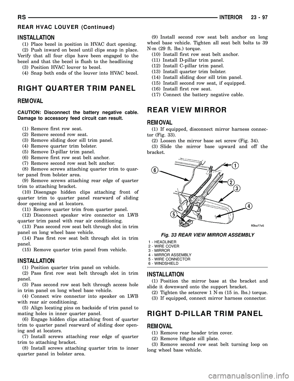
(1) If equipped, disconnect mirror harness connec-
tor (Fig. 33).
(2) Loosen the mirror base set screw (Fig. 34).
(3) Slide the mirror base upward and off the
bracket.
INSTALLATION
(1) Position the mirror base at the bracket and
slide it downward onto the support bracket.
(2) Tighten the setscrew 1 N´m (15 in. lbs.) torque.
(3) If equipped, connect mirror harness connector.
RIGHT D-PILLAR TRIM PANEL
REMOVAL
(1) Remove rear header trim cover.
(2) Remove liftgate sill plate.
(3) Remove second row seat belt turning loop on
long wheel base vehicle.
Fig. 33 REAR VIEW MIRROR ASSEMBLY
1 - HEADLINER
2 - WIRE COVER
3 - MIRROR
4 - MIRROR ASSEMBLY
5 - WIRE CONNECTOR
6 - WINDSHIELD
RSINTERIOR23-97
REAR HVAC LOUVER (Continued)
Page 1877 of 2339
(4) Remove bolt attaching second row seat belt,
anchor to quarter on short wheel base vehicle.
(5)
Disengage hidden clips attaching trim to D-pillar.
(6) Remove D-pillar trim panel from D-pillar.
(7) Disconnect speaker wire connector, if equipped.
(8) Pass second row seat belt, if equipped, through
slot in trim panel on short wheel base vehicle.
(9) Remove D-pillar trim from vehicle.
INSTALLATION
(1) Position D-pillar trim on vehicle.
(2) Pass second row seat belt, if equipped, through
slot in trim panel on short wheel base vehicle.
(3) Connect speaker wire connector to speaker, if
equipped.
(4) Align locating pins on backside of trim panel to
mating holes in D-pillar.
(5) Engage hidden clips attaching trim to D-pillar.
(6) Install screws attaching trim panel to attach-
ing bracket on short wheel base vehicle.
(7) Install quarter trim bolster on short wheel base
vehicle.
(8) Install bolt to attach second row seat belt, if
equipped, anchor to quarter on short wheel base
vehicle. Tighten all seat belt bolts to 39 N´m (29 ft.
lbs.) torque.
(9) Install second row seat belt turning loop on
long wheel base vehicle.
(10) Install liftgate sill plate.
(11) Install rear header trim cover.
SECOND ROW FLOOR TUB
CARPET INSERT - FOLD-IN-
FLOOR
REMOVAL
(1) Move both front seats to the full forward posi-
tion.(2) Fold second row seats into the floor well.
(3) Remove rear carpet ring and cover from vehi-
cle. (Refer to 23 - BODY/INTERIOR/REAR CARPET
RING AND COVER ASSEMBLY - REMOVAL).
(4) Remove second row seat from vehicle. Repeat
operation for other side, if necessary.
(5) Remove second row floor tub insert(s) from
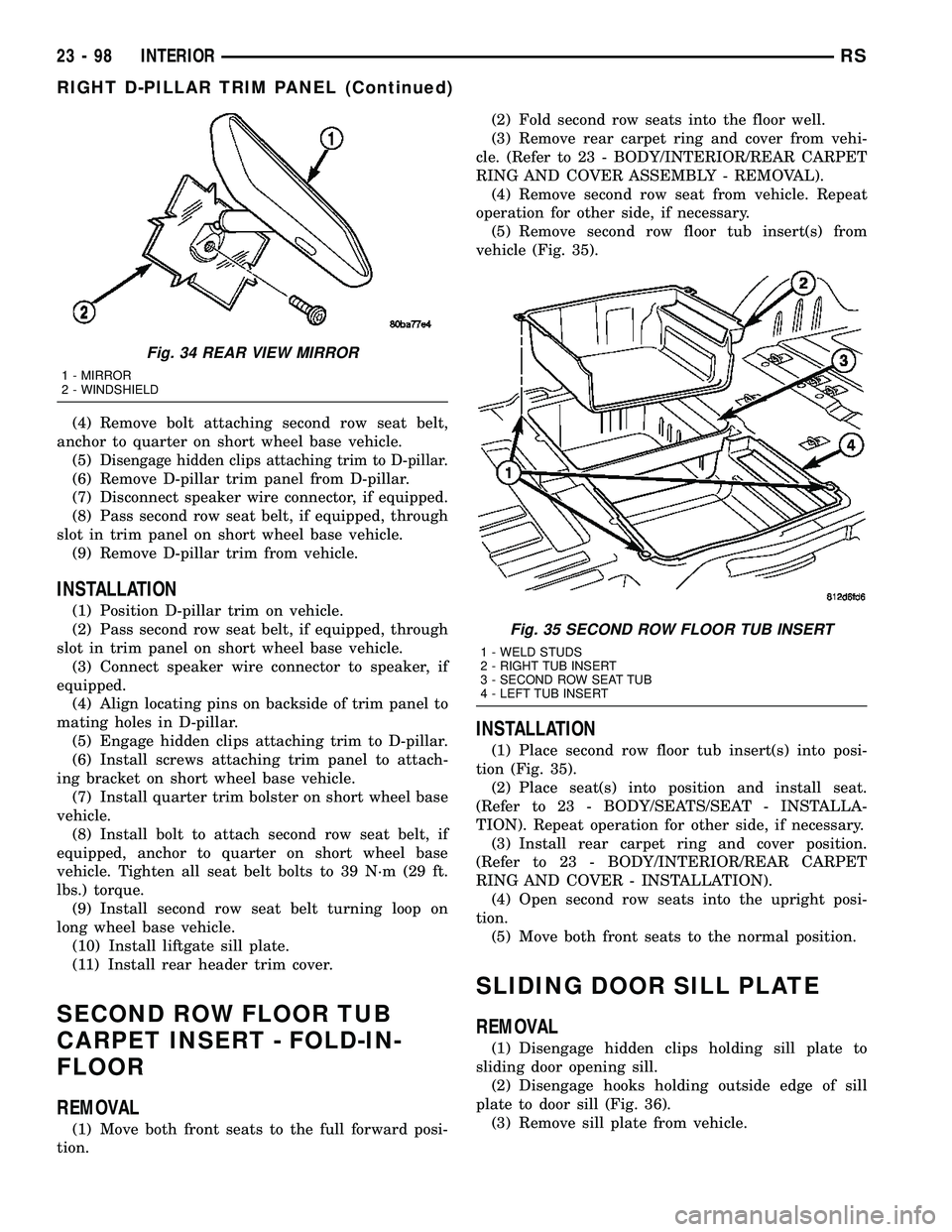
vehicle (Fig. 35).
INSTALLATION
(1) Place second row floor tub insert(s) into posi-
tion (Fig. 35).
(2) Place seat(s) into position and install seat.
(Refer to 23 - BODY/SEATS/SEAT - INSTALLA-
TION). Repeat operation for other side, if necessary.
(3) Install rear carpet ring and cover position.
(Refer to 23 - BODY/INTERIOR/REAR CARPET
RING AND COVER - INSTALLATION).
(4) Open second row seats into the upright posi-
tion.
(5) Move both front seats to the normal position.
SLIDING DOOR SILL PLATE
REMOVAL
(1) Disengage hidden clips holding sill plate to
sliding door opening sill.
(2) Disengage hooks holding outside edge of sill
plate to door sill (Fig. 36).
(3) Remove sill plate from vehicle.
Fig. 34 REAR VIEW MIRROR
1 - MIRROR
2 - WINDSHIELD
Fig. 35 SECOND ROW FLOOR TUB INSERT
1 - WELD STUDS
2 - RIGHT TUB INSERT
3 - SECOND ROW SEAT TUB
4 - LEFT TUB INSERT
23 - 98 INTERIORRS
RIGHT D-PILLAR TRIM PANEL (Continued)
Page 1884 of 2339
INSTALLATION
INSTALLATION
(1) Place child restraint seat module in position on
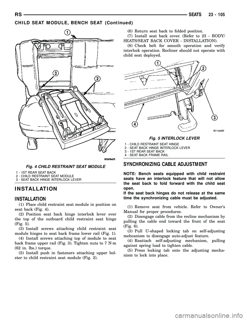
seat back (Fig. 4).
(2) Position seat back hinge interlock lever over
the top of the outboard child restraint seat hinge
(Fig. 5).
(3) Install screws attaching child restraint seat
module hinges to seat back frame lower rail (Fig. 1).
(4) Install screws attaching top of module to seat
back frame upper rail (Fig. 3). Tighten nuts to 7 N´m
(62 in. lbs.) torque.
(5) Install push in fasteners attaching upper bol-
ster to child restraint seat module (Fig. 2).(6) Return seat back to folded position.
(7) Install seat back cover. (Refer to 23 - BODY/
SEATS/SEAT BACK COVER - INSTALLATION).
(8) Check belt for smooth operation and verify
interlock operation. Recliner should not operate with
child seat deployed.
SYNCHRONIZING CABLE ADJUSTMENT
NOTE: Bench seats equipped with child restraint
seats have an interlock feature that will not allow
the seat back to fold forward with the child seat
open.
If the seat back hinges do not release at the same
time the synchronizing cable must be adjusted.
(1) Remove seat from vehicle. Refer to Owner's
Manual for proper procedures.
(2) Disengage cable from the recline mechanism by
pulling the cable end toward the front of the seat
(Fig. 6).
(3) Pull U-shaped locking tab on self-adjusting
mehcanism to disengage auto-adjust feature.
(4) Reattach self-adjusting mechanism, pulling
against spring load to tighten cable.
(5) Press locking tab onto the adjusting mecha-
nism to lock into place.
Fig. 4 CHILD RESTRAINT SEAT MODULE
1 - 1ST REAR SEAT BACK
2 - CHILD RESTRAINT SEAT MODULE
3 - SEAT BACK HINGE INTERLOCK LEVER
Fig. 5 INTERLOCK LEVER
1 - CHILD RESTRAINT SEAT HINGE
2 - SEAT BACK HINGE INTERLOCK LEVER
3 - 1ST REAR SEAT BACK
4 - SEAT BACK FRAME RAIL
RSSEATS23 - 105
CHILD SEAT MODULE, BENCH SEAT (Continued)
Page 1887 of 2339
RECLINER HANDLE
REMOVAL
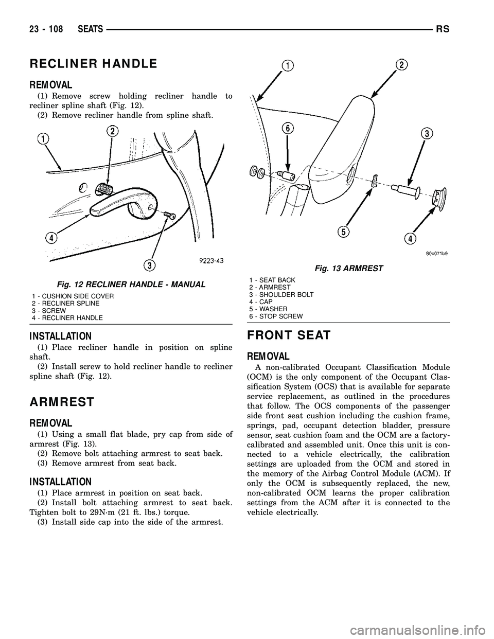
(1) Remove screw holding recliner handle to
recliner spline shaft (Fig. 12).
(2) Remove recliner handle from spline shaft.
INSTALLATION
(1) Place recliner handle in position on spline
shaft.
(2) Install screw to hold recliner handle to recliner
spline shaft (Fig. 12).
ARMREST
REMOVAL
(1) Using a small flat blade, pry cap from side of
armrest (Fig. 13).
(2) Remove bolt attaching armrest to seat back.
(3) Remove armrest from seat back.
INSTALLATION
(1) Place armrest in position on seat back.
(2) Install bolt attaching armrest to seat back.
Tighten bolt to 29N´m (21 ft. lbs.) torque.
(3) Install side cap into the side of the armrest.
FRONT SEAT
REMOVAL
A non-calibrated Occupant Classification Module
(OCM) is the only component of the Occupant Clas-
sification System (OCS) that is available for separate
service replacement, as outlined in the procedures
that follow. The OCS components of the passenger
side front seat cushion including the cushion frame,
springs, pad, occupant detection bladder, pressure
sensor, seat cushion foam and the OCM are a factory-
calibrated and assembled unit. Once this unit is con-
nected to a vehicle electrically, the calibration
settings are uploaded from the OCM and stored in
the memory of the Airbag Control Module (ACM). If
only the OCM is subsequently replaced, the new,
non-calibrated OCM learns the proper calibration
settings from the ACM after it is connected to the
vehicle electrically.
Fig. 12 RECLINER HANDLE - MANUAL
1 - CUSHION SIDE COVER
2 - RECLINER SPLINE
3 - SCREW
4 - RECLINER HANDLE
Fig. 13 ARMREST
1 - SEAT BACK
2 - ARMREST
3 - SHOULDER BOLT
4 - CAP
5 - WASHER
6 - STOP SCREW
23 - 108 SEATSRS