2005 CHRYSLER CARAVAN ors
[x] Cancel search: orsPage 1863 of 2339
(3) Roll carpet forward under instrument panel
(Fig. 8).
(4) Install push pins fasteners through carpet and
grommet into floor to attach carpet to floor in front
seat area.
(5) Pull wire harnesses through the carpet as
needed.
(6) Smooth out the carpet and allowing weld studs
to go all the way through the carpet.
(7) Install rear push pins fasteners attaching rear
of carpet.
(8) Place third row carpet cover into position and
press clips into position (Fig. 9).
(9) Slide the carpet under the quarter trim panel
into position.
(10) Install lower B-pillar trim covers.
(11) Install sliding door sill plates. (Refer to 23 -
BODY/INTERIOR/SLIDING DOOR SILL PLATE -
INSTALLATION).
(12) Install front carpet trim ring and cover (Fig.
7). (Refer to 23 - BODY/INTERIOR/CARPETS TRIM
RING AND COVER - INSTALLATION)
(13) Install seat belt anchors at the passenger side
B-pillar and driver side C-pillars
(14) Install kick plate and heel pad at the gas
pedal
(15) Install winch plug (spare tire winch) (Fig. 6).
(16) Install front cowl panels and sill plates.
(17) Install heel blocker (plastic block below accel-
erator pedal).
(18) Install the floor console base tray and discon-
nect wire connector from the base tray. (Refer to 23 -
BODY/INTERIOR/FLOOR CONSOLE BASE TRAY -
INSTALLATION).
(19) Install instrument panel lower console. (Refer
to 23 - BODY/INSTRUMENT PANEL/STORAGE
BIN - INSTALLATION).
(20) Install front seats. (Refer to 23 - BODY/
SEATS/SEAT - REMOVAL).
(21) Install floor mats.CARPET TRIM RING AND
COVER - FOLD-IN-FLOOR
REMOVAL
(1) Move front seats to the full forward position.
(2) Fold the second row seats into the floor.
(3) Remove the load floor plugs (Fig. 10).
(4) Remove the ten weld nuts.
(5) Open door covers (Fig. 11).
(6) Remove the four inter weld nuts (Fig. 12).
(7) Raise the front trim ring and cover up off of
the weld studs and remove from vehicle.
INSTALLATION
(1) Place front trim ring and cover assembly into
position.
(2) Open door covers (Fig. 11).
(3) Install the four inter weld nuts (Fig. 12).
(4) Close door covers.
(5) Install the ten weld nuts (Fig. 10).
(6) Install the eight load floor plugs.
(7) Open the second row seats into position.
(8) Move front seats to the position.
23 - 84 INTERIORRS
CARPETS - FOLD-IN-FLOOR (Continued)
Page 1866 of 2339
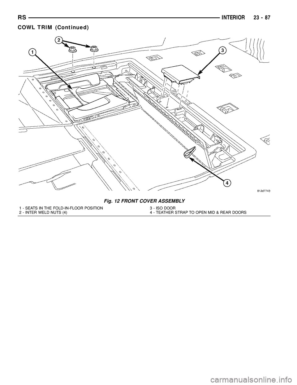
Fig. 12 FRONT COVER ASSEMBLY
1 - SEATS IN THE FOLD-IN-FLOOR POSITION
2 - INTER WELD NUTS (4)3 - ISO DOOR
4 - TEATHER STRAP TO OPEN MID & REAR DOORS
RSINTERIOR23-87
COWL TRIM (Continued)
Page 1870 of 2339
HEADLINER
REMOVAL
(1) Remove sun visors and vanity mirrors.
(2) Remove sun visor center supports.
(3) If equipped, remove coat hooks.
(4) If equipped, remove roof rail modules.
(5) Remove A-pillar trim covers. (Refer to 23 -
BODY/INTERIOR/A-PILLAR TRIM - REMOVAL).
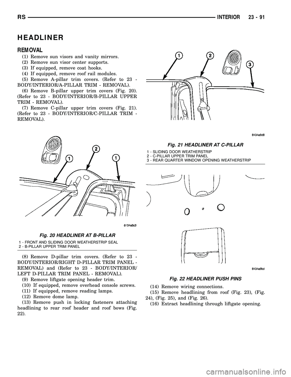
(6) Remove B-pillar upper trim covers (Fig. 20).
(Refer to 23 - BODY/INTERIOR/B-PILLAR UPPER
TRIM - REMOVAL).
(7) Remove C-pillar upper trim covers (Fig. 21).
(Refer to 23 - BODY/INTERIOR/C-PILLAR TRIM -
REMOVAL).
(8) Remove D-pillar trim covers. (Refer to 23 -
BODY/INTERIOR/RIGHT D-PILLAR TRIM PANEL -
REMOVAL) and (Refer to 23 - BODY/INTERIOR/
LEFT D-PILLAR TRIM PANEL - REMOVAL).
(9) Remove liftgate opening header trim.
(10) If equipped, remove overhead console screws.
(11) If equipped, remove reading lamps.
(12) Remove dome lamp.
(13) Remove push in locking fasteners attaching
headlining to rear roof header and roof bows (Fig.
22).(14) Remove wiring connections.
(15) Remove headlining from roof (Fig. 23), (Fig.
24), (Fig. 25), and (Fig. 26).
(16) Extract headlining through liftgate opening.
Fig. 20 HEADLINER AT B-PILLAR
1 - FRONT AND SLIDING DOOR WEATHERSTRIP SEAL
2 - B-PILLAR UPPER TRIM PANEL
Fig. 21 HEADLINER AT C-PILLAR
1 - SLIDING DOOR WEATHERSTRIP
2 - C-PILLAR UPPER TRIM PANEL
3 - REAR QUARTER WINDOW OPENING WEATHERSTRIP
Fig. 22 HEADLINER PUSH PINS
RSINTERIOR23-91
Page 1871 of 2339
INSTALLATION
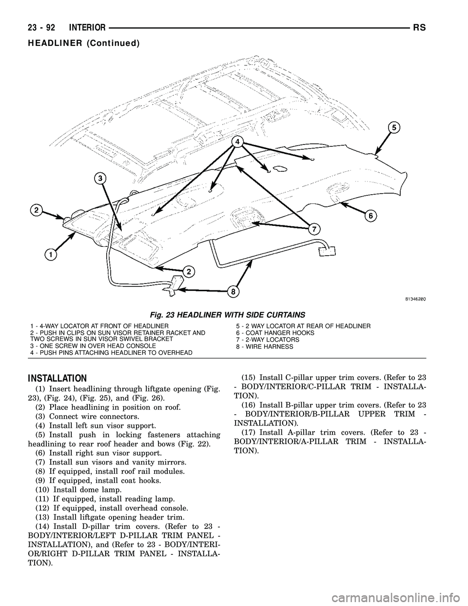
(1) Insert headlining through liftgate opening (Fig.
23), (Fig. 24), (Fig. 25), and (Fig. 26).
(2) Place headlining in position on roof.
(3) Connect wire connectors.
(4) Install left sun visor support.
(5) Install push in locking fasteners attaching
headlining to rear roof header and bows (Fig. 22).
(6) Install right sun visor support.
(7) Install sun visors and vanity mirrors.
(8) If equipped, install roof rail modules.
(9) If equipped, install coat hooks.
(10) Install dome lamp.
(11) If equipped, install reading lamp.
(12) If equipped, install overhead console.
(13) Install liftgate opening header trim.
(14) Install D-pillar trim covers. (Refer to 23 -
BODY/INTERIOR/LEFT D-PILLAR TRIM PANEL -
INSTALLATION), and (Refer to 23 - BODY/INTERI-
OR/RIGHT D-PILLAR TRIM PANEL - INSTALLA-
TION).(15) Install C-pillar upper trim covers. (Refer to 23
- BODY/INTERIOR/C-PILLAR TRIM - INSTALLA-
TION).
(16) Install B-pillar upper trim covers. (Refer to 23
- BODY/INTERIOR/B-PILLAR UPPER TRIM -
INSTALLATION).
(17) Install A-pillar trim covers. (Refer to 23 -
BODY/INTERIOR/A-PILLAR TRIM - INSTALLA-
TION).
Fig. 23 HEADLINER WITH SIDE CURTAINS
1 - 4-WAY LOCATOR AT FRONT OF HEADLINER
2 - PUSH IN CLIPS ON SUN VISOR RETAINER RACKET AND
TWO SCREWS IN SUN VISOR SWIVEL BRACKET
3 - ONE SCREW IN OVER HEAD CONSOLE
4 - PUSH PINS ATTACHING HEADLINER TO OVERHEAD5-2WAYLOCATOR AT REAR OF HEADLINER
6 - COAT HANGER HOOKS
7 - 2-WAY LOCATORS
8 - WIRE HARNESS
23 - 92 INTERIORRS
HEADLINER (Continued)
Page 1876 of 2339
INSTALLATION
(1) Place bezel in position in HVAC duct opening.
(2) Push inward on bezel until clips snap in place.
Verify that all four clips have been engaged to the
bezel and that the bezel is flush to the headlining
(3) Position HVAC louver to bezel.
(4) Snap both ends of the louver into HVAC bezel.
RIGHT QUARTER TRIM PANEL
REMOVAL
CAUTION: Disconnect the battery negative cable.
Damage to accessory feed circuit can result.
(1) Remove first row seat.
(2) Remove second row seat.
(3) Remove sliding door sill trim panel.
(4) Remove quarter trim bolster.
(5) Remove D-pillar trim panel.
(6) Remove first row seat belt anchor.
(7) Remove second row seat belt anchor.
(8) Remove screws attaching quarter trim to quar-
ter panel from bolster area.
(9) Remove screws attaching rear edge of quarter
trim to attaching bracket.
(10) Disengage hidden clips attaching front of
quarter trim to quarter panel rearward of sliding
door opening and at locators.
(11) Remove quarter trim from quarter panel.
(12) Disconnect speaker wire connector on LWB
quarter trim panel with rear air conditioning.
(13) Pass second row seat belt through slot in trim
panel on long wheel base vehicle.
(14) Pass first row seat belt through slot in trim
panel.
(15) Remove quarter trim panel from vehicle.
INSTALLATION
(1) Position quarter trim panel on vehicle.
(2) Pass first row seat belt through slot in trim
panel.
(3) Pass second row seat belt through access hole
in trim panel on long wheel base vehicle.
(4) Connect wire connector into speaker on LWB
with rear air conditioning.
(5) Align locating pins on backside of trim panel to
mating holes in inner quarter panel.
(6) Engage hidden clips attaching front of quarter
trim to quarter panel rearward of sliding door open-
ing and at locators.
(7) Install screws attaching rear edge of quarter
trim to attaching bracket.
(8) Install screws attaching quarter trim to inner
quarter panel in bolster area.(9) Install second row seat belt anchor on long
wheel base vehicle. Tighten all seat belt bolts to 39
N´m (29 ft. lbs.) torque.
(10) Install first row seat belt anchor.
(11) Install D-pillar trim panel.
(12) Install C-pillar trim panel.
(13) Install quarter trim bolster.
(14) Install sliding door sill trim panel.
(15) Install second row seat, if equipped.
(16) Install first row seat.
(17) Connect the battery negative cable.
REAR VIEW MIRROR
REMOVAL
(1) If equipped, disconnect mirror harness connec-
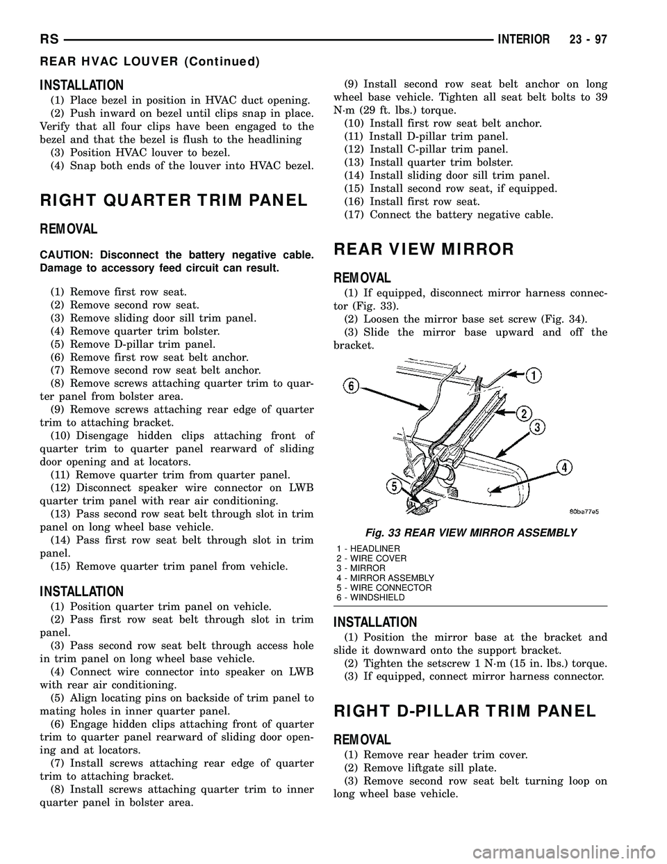
tor (Fig. 33).
(2) Loosen the mirror base set screw (Fig. 34).
(3) Slide the mirror base upward and off the
bracket.
INSTALLATION
(1) Position the mirror base at the bracket and
slide it downward onto the support bracket.
(2) Tighten the setscrew 1 N´m (15 in. lbs.) torque.
(3) If equipped, connect mirror harness connector.
RIGHT D-PILLAR TRIM PANEL
REMOVAL
(1) Remove rear header trim cover.
(2) Remove liftgate sill plate.
(3) Remove second row seat belt turning loop on
long wheel base vehicle.
Fig. 33 REAR VIEW MIRROR ASSEMBLY
1 - HEADLINER
2 - WIRE COVER
3 - MIRROR
4 - MIRROR ASSEMBLY
5 - WIRE CONNECTOR
6 - WINDSHIELD
RSINTERIOR23-97
REAR HVAC LOUVER (Continued)
Page 1879 of 2339
PAINT
TABLE OF CONTENTS
page page
PAINT
SPECIFICATIONS - COLOR CODE CHARTS . . 100
BASE COAT/CLEARCOAT FINISH
DESCRIPTION........................101
PAINT CODE
DESCRIPTION........................101PAINTED TOUCH-UP
DESCRIPTION........................101
FINESSE SANDING/BUFFING & POLISHING
DESCRIPTION........................101
PAINT
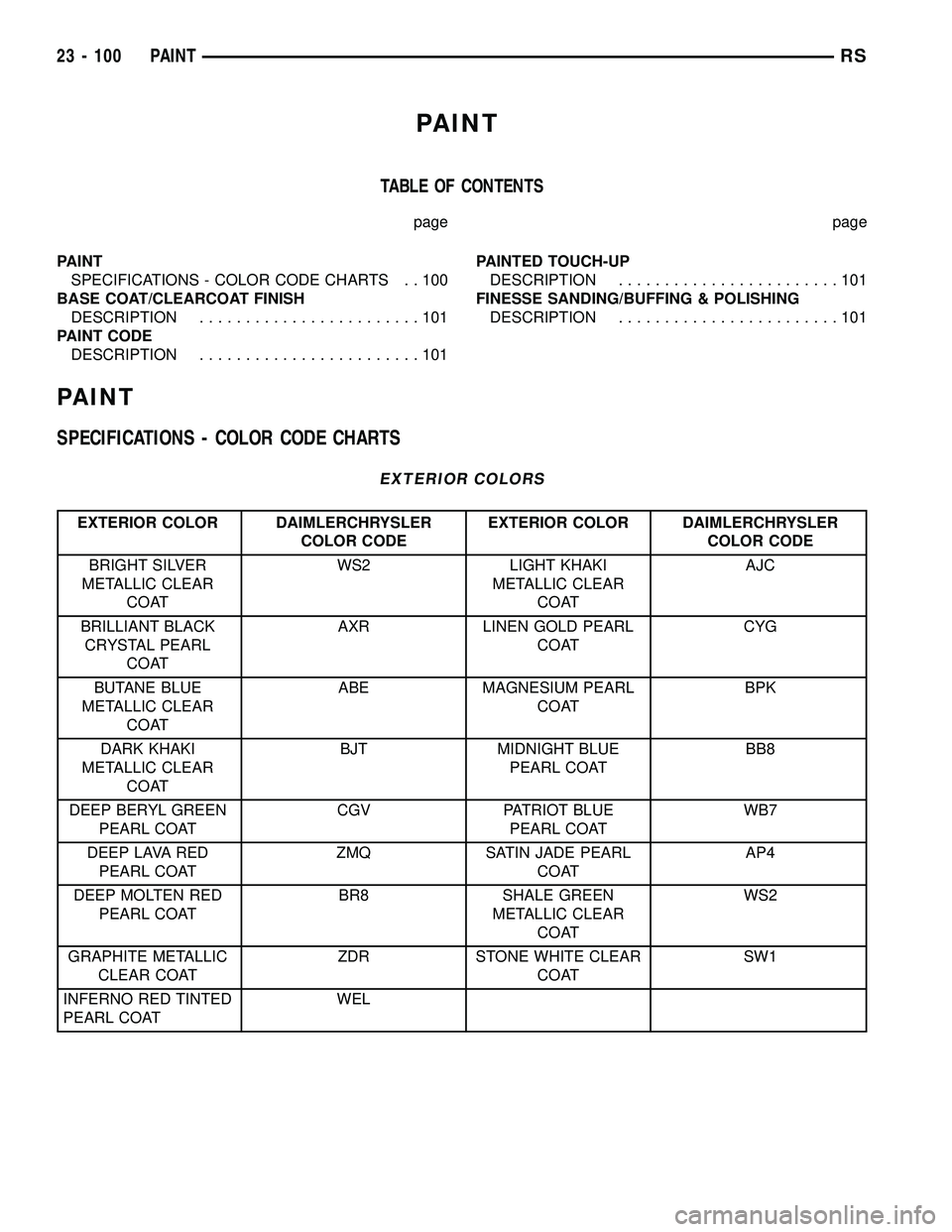
SPECIFICATIONS - COLOR CODE CHARTS
EXTERIOR COLORS
EXTERIOR COLOR DAIMLERCHRYSLER
COLOR CODEEXTERIOR COLOR DAIMLERCHRYSLER
COLOR CODE
BRIGHT SILVER
METALLIC CLEAR
COATWS2 LIGHT KHAKI
METALLIC CLEAR
COATAJC
BRILLIANT BLACK
CRYSTAL PEARL
COATAXR LINEN GOLD PEARL
COATCYG
BUTANE BLUE
METALLIC CLEAR
COATABE MAGNESIUM PEARL
COATBPK
DARK KHAKI
METALLIC CLEAR
COATBJT MIDNIGHT BLUE
PEARL COATBB8
DEEP BERYL GREEN
PEARL COATCGV PATRIOT BLUE
PEARL COATWB7
DEEP LAVA RED
PEARL COATZMQ SATIN JADE PEARL
COATAP4
DEEP MOLTEN RED
PEARL COATBR8 SHALE GREEN
METALLIC CLEAR
COATWS2
GRAPHITE METALLIC
CLEAR COATZDR STONE WHITE CLEAR
COATSW1
INFERNO RED TINTED
PEARL COATWEL
23 - 100 PAINTRS
Page 1880 of 2339
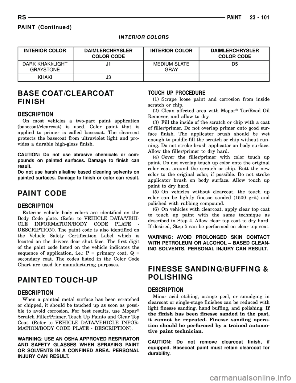
INTERIOR COLORS
INTERIOR COLOR DAIMLERCHRYSLER
COLOR CODEINTERIOR COLOR DAIMLERCHRYSLER
COLOR CODE
DARK KHAKI/LIGHT
GRAYSTONEJ1 MEDIUM SLATE
GRAYD5
KHAKI J3
BASE COAT/CLEARCOAT
FINISH
DESCRIPTION
On most vehicles a two-part paint application
(basecoat/clearcoat) is used. Color paint that is
applied to primer is called basecoat. The clearcoat
protects the basecoat from ultraviolet light and pro-
vides a durable high-gloss finish.
CAUTION: Do not use abrasive chemicals or com-
pounds on painted surfaces. Damage to finish can
result.
Do not use harsh alkaline based cleaning solvents on
painted surfaces. Damage to finish or color can result.
PAINT CODE
DESCRIPTION
Exterior vehicle body colors are identified on the
Body Code plate. (Refer to VEHICLE DATA/VEHI-
CLE INFORMATION/BODY CODE PLATE -
DESCRIPTION). The paint code is also identified on
the Vehicle Safety Certification Label which is
located on the drivers door shut face. The first digit
of the paint code listed on the vehicle indicates the
sequence of application, i.e.: P = primary coat, Q =
secondary coat. The codes listed in the Color Code
Chart are used for manufacturing purposes.
PAINTED TOUCH-UP
DESCRIPTION
When a painted metal surface has been scratched
or chipped, it should be touched up as soon as possi-
ble to avoid corrosion. For best results, use Mopart
Scratch Filler/Primer, Touch Up Paints and Clear Top
Coat. (Refer to VEHICLE DATA/VEHICLE INFOR-
MATION/BODY CODE PLATE - DESCRIPTION).
WARNING: USE AN OSHA APPROVED RESPIRATOR
AND SAFETY GLASSES WHEN SPRAYING PAINT
OR SOLVENTS IN A CONFINED AREA. PERSONAL
INJURY CAN RESULT.
TOUCH UP PROCEDURE
(1) Scrape loose paint and corrosion from inside
scratch or chip.
(2) Clean affected area with MopartTar/Road Oil
Remover, and allow to dry.
(3) Fill the inside of the scratch or chip with a coat
of filler/primer. Do not overlap primer onto good sur-
face finish. The applicator brush should be wet
enough to puddle-fill the scratch or chip without run-
ning. Do not stroke brush applicator on body surface.
Allow the filler/primer to dry hard.
(4) Cover the filler/primer with color touch up
paint. Do not overlap touch up color onto the original
color coat around the scratch or chip. Butt the new
color to the original color, if possible. Do not stroke
applicator brush on body surface. Allow touch up
paint to dry hard.
(5) On vehicles without clearcoat, the touch up
color can be lightly finesse sanded (1500 grit) and
polished with rubbing compound.
(6) On vehicles with clearcoat, apply clear top coat
to touch up paint with the same technique as
described in Step 4. Allow clear top coat to dry hard.
If desired, Step 5 can be performed on clear top coat.
WARNING: AVOID PROLONGED SKIN CONTACT
WITH PETROLEUM OR ALCOHOL ± BASED CLEAN-
ING SOLVENTS. PERSONAL INJURY CAN RESULT.
FINESSE SANDING/BUFFING &
POLISHING
DESCRIPTION
Minor acid etching, orange peel, or smudging in
clearcoat or single-stage finishes can be reduced with
light finesse sanding, hand buffing, and polishing.If
the finish has been finesse sanded in the past,
it cannot be repeated. Finesse sanding opera-
tion should be performed by a trained automo-
tive paint technician.
CAUTION: Do not remove clearcoat finish, if
equipped. Basecoat paint must retain clearcoat for
durability.
RSPAINT23 - 101
PAINT (Continued)
Page 1888 of 2339
If any of the remaining OCS components of the
passenger side front seat cushion require replace-
ment, they are serviced only as a factory-calibrated,
assembled, and tamper-evident service replacement
package. This package includes the assembled frame,
springs, pad, bladder, sensor, foam, wiring and a cal-
ibrated OCM. When installing this package, always
replace all of the existing components with the new
components as a unit. Do not attempt to separate or
disconnect any of the new OCS components con-
tained in the service replacement package from each
other, and do not attempt to reuse any of the
replaced components in this or any other vehicle.
Once any of the original factory-installed compo-
nents except the OCM have been replaced with the
service replacement package components, the OCM
can only be serviced by replacing the entire passen-
ger side front seat cushion unit with another com-
plete service replacement package. (Refer to 23 -
BODY/SEATS/SEAT CUSHION - FRONT -
REMOVAL).
WARNING: TO AVOID PERSONAL INJURY OR
DEATH, ON VEHICLES EQUIPPED WITH AIRBAGS,
DISABLE THE SUPPLEMENTAL RESTRAINT SYS-
TEM BEFORE ATTEMPTING ANY STEERING
WHEEL, STEERING COLUMN, AIRBAG, OCCUPANT
CLASSIFICATION SYSTEM, SEAT BELT TEN-
SIONER, IMPACT SENSOR, OR INSTRUMENT
PANEL COMPONENT DIAGNOSIS OR SERVICE.
DISCONNECT AND ISOLATE THE BATTERY NEGA-
TIVE (GROUND) CABLE, THEN WAIT TWO MINUTES
FOR THE SYSTEM CAPACITOR TO DISCHARGE
BEFORE PERFORMING FURTHER DIAGNOSIS OR
SERVICE. THIS IS THE ONLY SURE WAY TO DIS-
ABLE THE SUPPLEMENTAL RESTRAINT SYSTEM.
FAILURE TO TAKE THE PROPER PRECAUTIONS
COULD RESULT IN ACCIDENTAL AIRBAG DEPLOY-
MENT.
WARNING: TO AVOID PERSONAL INJURY OR
DEATH ON VEHICLES EQUIPPED WITH THE OCCU-
PANT CLASSIFICATION SYSTEM (OCS), ONLY THE
OCCUPANT CLASSIFICATION MODULE (OCM) AND
THE SEAT CUSHION TRIM MAY BE SERVICED SEP-
ARATELY. ALL OTHER COMPONENTS OF THE PAS-
SENGER SIDE FRONT SEAT CUSHION ASSEMBLY
MUST BE SERVICED ONLY AS A COMPLETE FAC-
TORY-CALIBRATED, ASSEMBLED AND TAMPER-EV-
IDENT SERVICE REPLACEMENT PACKAGE. THIS
PACKAGE INCLUDES THE FRAME, SPRINGS, PAD,
BLADDER, SENSOR, FOAM, WIRING AND A CALI-
BRATED OCM. WHEN INSTALLING THIS PACKAGE
ALWAYS REPLACE ALL OF THE EXISTING COMPO-
NENTS WITH THE NEW COMPONENTS AS A UNIT.
DO NOT ATTEMPT TO SEPARATE OR DISCONNECTANY OF THE NEW OCS COMPONENTS IN THE SER-
VICE REPLACEMENT PACKAGE FROM EACH
OTHER, AND DO NOT ATTEMPT TO REUSE ANY OF
THE REPLACED COMPONENTS IN THIS OR ANY
OTHER VEHICLE. FAILURE TO TAKE THE PROPER
PRECAUTIONS COULD RESULT IN FAILURE OF
THE PASSENGER AIRBAG TO DEPLOY WHEN
REQUIRED, OR IN PASSENGER AIRBAG DEPLOY-
MENT WHEN NOT REQUIRED.
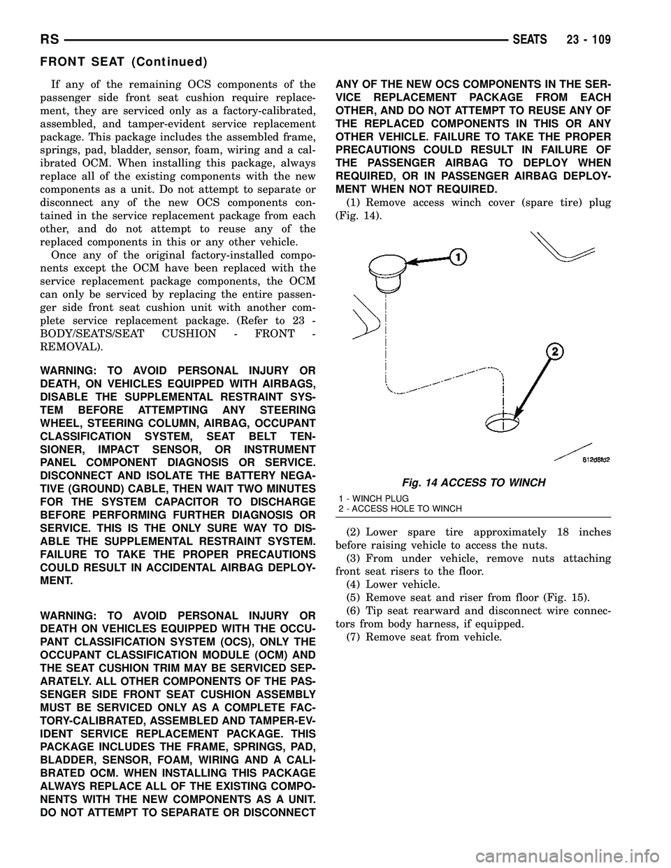
(1) Remove access winch cover (spare tire) plug
(Fig. 14).
(2) Lower spare tire approximately 18 inches
before raising vehicle to access the nuts.
(3) From under vehicle, remove nuts attaching
front seat risers to the floor.
(4) Lower vehicle.
(5) Remove seat and riser from floor (Fig. 15).
(6) Tip seat rearward and disconnect wire connec-
tors from body harness, if equipped.
(7) Remove seat from vehicle.
Fig. 14 ACCESS TO WINCH
1 - WINCH PLUG
2 - ACCESS HOLE TO WINCH
RSSEATS23 - 109
FRONT SEAT (Continued)