2005 CHRYSLER CARAVAN traction control
[x] Cancel search: traction controlPage 974 of 2339

Component Page
Rear Blower Front Control Switch (3 Zone
MTC)......................... 8W-80-124
Rear Blower Motor Power Module C1 (3 Zone
ATC) .......................... 8W-80-125
Rear Blower Motor Power Module C2 (3 Zone
ATC) .......................... 8W-80-125
Rear Blower Rear Control Switch C1 (3 Zone
MTC)......................... 8W-80-125
Rear Blower Rear Control Switch C2 (3 Zone
MTC)......................... 8W-80-125
Rear Dome Lamp (Except Luxury)..... 8W-80-126
Rear Intrusion Sensor (United
Kingdom)...................... 8W-80-126
Rear Mode Motor (3 Zone ATC)....... 8W-80-126
Rear Power Outlet................. 8W-80-126
Rear Temperature Motor (3 Zone ATC) . . 8W-80-127
Rear View Mirror C1 (Luxury)........ 8W-80-127
Rear View Mirror C2 (Hands Free)..... 8W-80-127
Rear Wiper Motor.................. 8W-80-128
Recirculation Door Actuator.......... 8W-80-128
Right B-Pillar Switch (Power Sliding
Door).......................... 8W-80-128
Right Cinch/Release Motor (Power Sliding
Door).......................... 8W-80-128
Right Curtain Airbag Squib.......... 8W-80-129
Right Cylinder Lock Switch (Export) . . . 8W-80-129
Right Door Speaker................ 8W-80-129
Right Fog Lamp................... 8W-80-129
Right Front Door Ajar Switch (Base) . . . 8W-80-130
Right Front Door Lock Motor/Ajar Switch (Except
Base).......................... 8W-80-130
Right Front Impact Sensor........... 8W-80-130
Right Front Park/Turn Signal Lamp.... 8W-80-130
Right Front Wheel Speed Sensor...... 8W-80-131
Right Full Open Switch (Power Sliding
Door).......................... 8W-80-131
Right Headlamp (Caravan/Voyager Except
Export)........................ 8W-80-131
Right Headlamp (Town And Country) . . . 8W-80-131
Right Headlamp Leveling Motor
(Export)....................... 8W-80-132
Right High Beam Lamp (Export)...... 8W-80-132
Right Instrument Panel Speaker...... 8W-80-132
Right Liftgate Flood Lamp........... 8W-80-132
Right Low Beam Lamp (Export)....... 8W-80-133
Right Mid Reading Lamp (Premium/
Luxury)........................ 8W-80-133
Right Park Lamp (Export)........... 8W-80-133
Right Power Mirror................ 8W-80-133
Right Rear Lamp Assembly.......... 8W-80-134
Right Rear Pillar Speaker (Highline
Audio)......................... 8W-80-134Component Page
Right Rear Reading Lamp (Luxury).... 8W-80-134
Right Rear Speaker................ 8W-80-134
Right Rear Vent Motor.............. 8W-80-135
Right Rear Wheel Speed Sensor....... 8W-80-135
Right Remote Radio Switch.......... 8W-80-135
Right Repeater Lamp (Export)........ 8W-80-135
Right Side Impact Sensor 1 (Export) . . . 8W-80-135
Right Side Impact Sensor 1 (Except
Export)........................ 8W-80-136
Right Side Impact Sensor 2.......... 8W-80-136
Right Side Impact Sensor 3.......... 8W-80-136
Right Sliding Door Control Module C1 (Power
Sliding Door)................... 8W-80-136
Right Sliding Door Control Module C2 (Power
Sliding Door)................... 8W-80-137
Right Sliding Door Latch Sensing Switch (Power
Sliding Door)................... 8W-80-137
Right Sliding Door Lock Motor (Power Sliding
Door).......................... 8W-80-137
Right Sliding Door Lock Motor/Ajar Switch (Manual
Sliding Door)................... 8W-80-138
Right Sliding Door Motor (Power Sliding
Door).......................... 8W-80-138
Right Speed Control Switch.......... 8W-80-138
Right Turn Signal Lamp (Export)...... 8W-80-138
Right Visor/Vanity Lamp (Except Base/
Export)........................ 8W-80-139
Sentry Key Remote Entry Module
(SKREEM)..................... 8W-80-139
Siren (United Kingdom)............. 8W-80-139
Speed Control Servo (Gas)........... 8W-80-139
Sunroof Module (Except Export)....... 8W-80-140
Sunroof Switch (Except Export)....... 8W-80-140
Thatcham Alarm Module (United
Kingdom)...................... 8W-80-140
Throttle Position Sensor (Gas)........ 8W-80-141
Traction Control Switch............. 8W-80-141
Trailer Tow Connector (Except Export) . . 8W-80-141
Transmission Control Module (Diesel) . . 8W-80-141
Transmission Control Relay (Diesel).... 8W-80-143
Transmission Range Sensor.......... 8W-80-143
Transmission Solenoid/Pressure Switch
Assembly...................... 8W-80-143
Vehicle Speed Sensor (MTX).......... 8W-80-144
Washer Fluid Level Switch........... 8W-80-144
Washer Pump Motor................ 8W-80-144
Water In Fuel Sensor (Diesel)......... 8W-80-144
Wiper Module..................... 8W-80-144
RS8W-80 CONNECTOR PIN-OUTS8W-80-5
Page 984 of 2339

BODY CONTROL MODULE C4 - BLACK/GRAY 34 WAY
CAV CIRCUIT FUNCTION
1- -
2 E12 20OR/GY PANEL LAMPS DRIVER
3 E19 20OR/BR (AUTOMATIC HEAD-
LAMPS)HEADLAMP SWITCH DIMMER SIGNAL
4- -
5 G150 22VT/BR INSTRUMENT CLUSTER WAKE UP SENSE
6- -
7 P162 20LG/DG (EXPORT) PASSENGER FOLDING MIRROR RELAY CONTROL
8- -
9 L161 20WT/LG LEFT TURN INDICATOR DRIVER
10 F504 20GY/PK FUSED IGNITION SWITCH OUTPUT (RUN)
11 E14 20OR/TN PANEL LAMPS DRIVER
12 E13 20OR/WT PANEL LAMPS DRIVER
13 X920 22GY/OR (REMOTE AUDIO) RADIO CONTROL MUX RETURN
14 G900 20VT/DB IGNITION SWITCH SENSE RETURN
15 - -
16 - -
17 L160 20WT/TN RIGHT TURN INDICATOR DRIVER
18 - -
19 - -
20 - -
21 - -
22 G902 22VT/LB MULTI-FUNCTION SWITCH MUX RETURN
23 - -
24 - -
25 - -
26 - -
27 - -
28 - -
29 - -
30 - -
31 - -
32 B27 20DG/WT (TRACTION CONTROL) TRACTION CONTROL SWITCH SENSE
33 P136 20TN/YL (EXPORT) FOLDING MIRROR SWITCH SENSE
34 G26 22VT/OR CHIME DRIVER
RS8W-80 CONNECTOR PIN-OUTS8W-80-15
Page 1110 of 2339

THROTTLE POSITION SENSOR (GAS) - GRAY 3 WAY
CAV CIRCUIT FUNCTION
1 K900 18DB/DG SENSOR GROUND
2 K22 18BR/OR TP SIGNAL
3 F855 20PK/YL 5 VOLT SUPPLY
TRACTION CONTROL SWITCH - BLACK 2 WAY
CAV CIRCUIT FUNCTION
1 B27 20DG/WT TRACTION CONTROL SWITCH SENSE
2 Z427 20BK/WT GROUND
TRAILER TOW CONNECTOR (EXCEPT EXPORT)-4WAY
CAV CIRCUIT FUNCTION
1 L62 18LG RIGHT REAR TURN SIGNAL DRIVER
2 Z362 18WT GROUND
3 L77 18BR FUSED PARK LAMP RELAY OUTPUT (LEFT)
4 L63 18YL LEFT REAR TURN SIGNAL DRIVER
TRANSMISSION CONTROL MODULE (DIESEL) - BLACK
CAV CIRCUIT FUNCTION
1 T1 18DG/LB TRS T1 SENSE
2- -
3 T3 18DG/DB TRS T3 SENSE
4- -
5- -
6 K24 20BR/LB CRANKSHAFT POSITION SENSOR SIGNAL NO.2
7 D15 20DG/YL SCI TRANSMIT (TCM)
8 T751 20YL FUSED IGNITION SWITCH OUTPUT (START)
9 T9 18DG/TN OVERDRIVE PRESSURE SWITCH SENSE
10 T10 20DG/LG TORQUE MANAGEMENT REQUEST SENSE
11 F1 18PK/WT FCM OUTPUT (UNLOCK-RUN-START)
12 K23 20BR/OR ACCELERATOR PEDAL POSITION SENSOR SIGNAL
NO.2
13 T13 18DG/VT SPEED SENSOR GROUND
14 T14 18DG/BR OUTPUT SPEED SENSOR SIGNAL
15 T15 18YL/BR TRANSMISSION CONTROL RELAY CONTROL
16 T16 18YL/OR TRANSMISSION CONTROL RELAY OUTPUT
17 T16 18YL/OR TRANSMISSION CONTROL RELAY OUTPUT
18 - -
19 T19 18YL/DB 2-4 SOLENOID CONTROL
20 T20 18DG/WT L/R SOLENOID CONTROL
21 - -
22 - -
RS8W-80 CONNECTOR PIN-OUTS8W - 80 - 141
Page 1125 of 2339
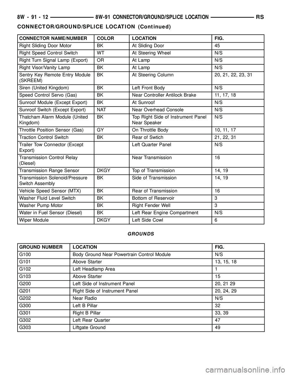
CONNECTOR NAME/NUMBER COLOR LOCATION FIG.
Right Sliding Door Motor BK At Sliding Door 45
Right Speed Control Switch WT At Steering Wheel N/S
Right Turn Signal Lamp (Export) OR At Lamp N/S
Right Visor/Vanity Lamp BK At Lamp N/S
Sentry Key Remote Entry Module
(SKREEM)BK At Steering Column 20, 21, 22, 23, 31
Siren (United Kingdom) BK Left Front Body N/S
Speed Control Servo (Gas) BK Near Controller Antilock Brake 11, 17, 18
Sunroof Module (Except Export) BK At Sunroof N/S
Sunroof Switch (Except Export) NAT Near Overhead Console N/S
Thatcham Alarm Module (United
Kingdom)BK Top Right Side of Instrument Panel
Near SpeakerN/S
Throttle Position Sensor (Gas) GY On Throttle Body 10, 11, 17
Traction Control Switch BK Rear of Swtich 21, 22, 31
Trailer Tow Connector (Except
Export)Left Quarter Panel N/S
Transmission Control Relay
(Diesel)Near Transmission 16
Transmission Range Sensor DKGY Top of Transmission 14, 19
Transmission Solenoid/Pressure
Switch AssemblyBK Side of Transmission 14, 19
Vehicle Speed Sensor (MTX) BK Rear of Transmission 16
Washer Fluid Level Switch BK Bottom of Reservoir 3
Washer Pump Motor BK Right Fender Well 3
Water in Fuel Sensor (Diesel) BK Left Rear Engine Compartment N/S
Wiper Module DKGY Left Side Cowl 6
GROUNDS
GROUND NUMBER LOCATION FIG.
G100 Body Ground Near Powertrain Control Module N/S
G101 Above Starter 13, 15, 18
G102 Left Headlamp Area 1
G103 Above Starter 15
G200 Left Side of Instrument Panel 20, 21 29
G201 Right Side of Instrument Panel 20, 24, 29
G202 Near Radio N/S
G300 Left B Pillar 32
G301 Right B Pillar 33, 39
G302 Left Rear Quarter 47
G303 Liftgate Ground 49
8W - 91 - 12 8W-91 CONNECTOR/GROUND/SPLICE LOCATIONRS
CONNECTOR/GROUND/SPLICE LOCATION (Continued)
Page 1419 of 2339
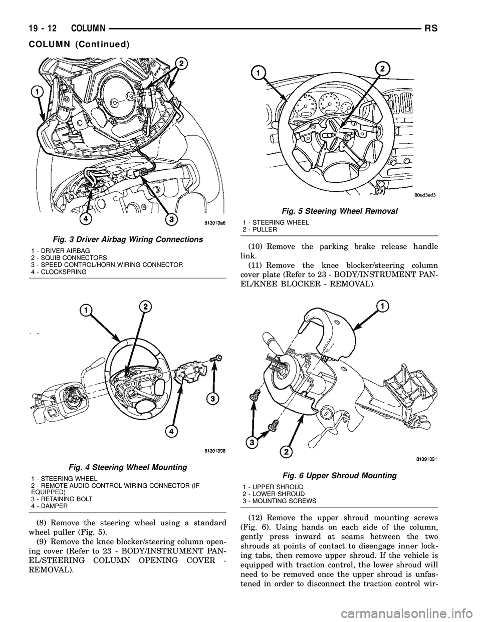
(8) Remove the steering wheel using a standard
wheel puller (Fig. 5).
(9) Remove the knee blocker/steering column open-
ing cover (Refer to 23 - BODY/INSTRUMENT PAN-
EL/STEERING COLUMN OPENING COVER -
REMOVAL).(10) Remove the parking brake release handle
link.
(11) Remove the knee blocker/steering column
cover plate (Refer to 23 - BODY/INSTRUMENT PAN-
EL/KNEE BLOCKER - REMOVAL).
(12) Remove the upper shroud mounting screws
(Fig. 6). Using hands on each side of the column,
gently press inward at seams between the two
shrouds at points of contact to disengage inner lock-
ing tabs, then remove upper shroud. If the vehicle is
equipped with traction control, the lower shroud will
need to be removed once the upper shroud is unfas-
tened in order to disconnect the traction control wir-
Fig. 3 Driver Airbag Wiring Connections
1 - DRIVER AIRBAG
2 - SQUIB CONNECTORS
3 - SPEED CONTROL/HORN WIRING CONNECTOR
4 - CLOCKSPRING
Fig. 4 Steering Wheel Mounting
1 - STEERING WHEEL
2 - REMOTE AUDIO CONTROL WIRING CONNECTOR (IF
EQUIPPED)
3 - RETAINING BOLT
4 - DAMPER
Fig. 5 Steering Wheel Removal
1 - STEERING WHEEL
2 - PULLER
Fig. 6 Upper Shroud Mounting
1 - UPPER SHROUD
2 - LOWER SHROUD
3 - MOUNTING SCREWS
19 - 12 COLUMNRS
COLUMN (Continued)
Page 1420 of 2339
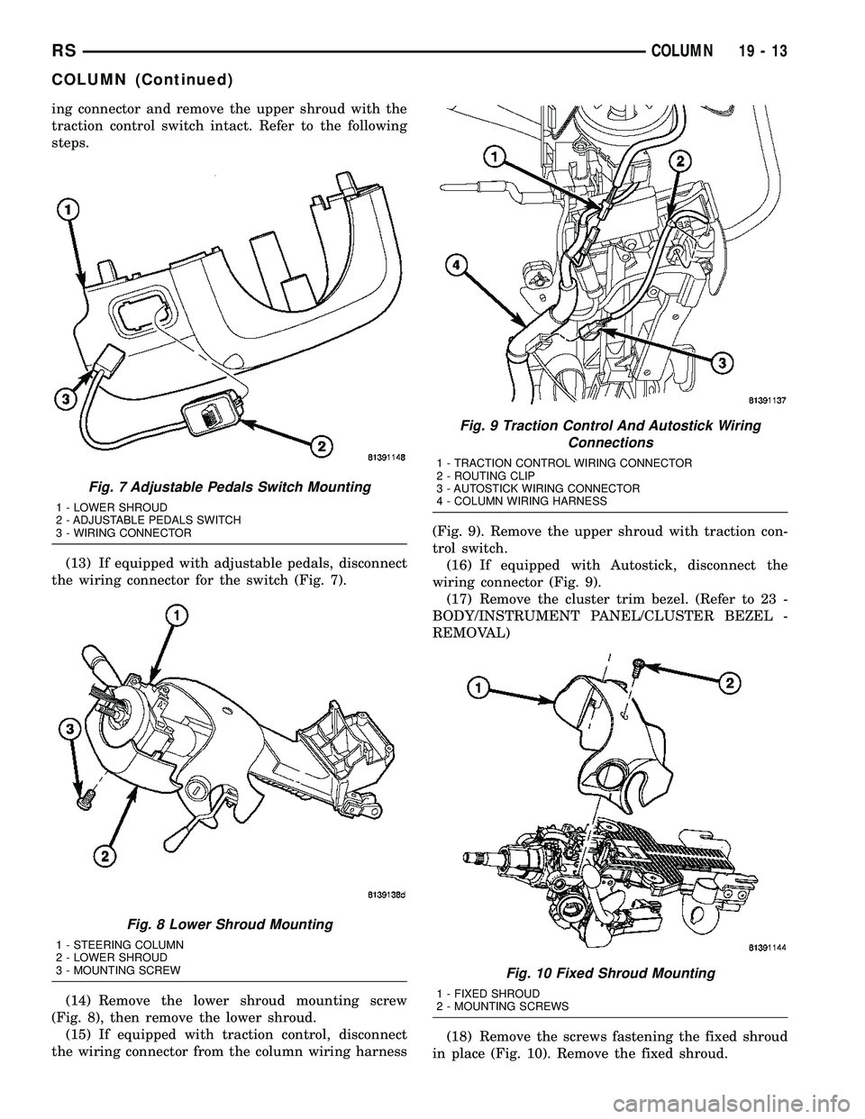
ing connector and remove the upper shroud with the
traction control switch intact. Refer to the following
steps.
(13) If equipped with adjustable pedals, disconnect
the wiring connector for the switch (Fig. 7).
(14) Remove the lower shroud mounting screw
(Fig. 8), then remove the lower shroud.
(15) If equipped with traction control, disconnect
the wiring connector from the column wiring harness(Fig. 9). Remove the upper shroud with traction con-
trol switch.
(16) If equipped with Autostick, disconnect the
wiring connector (Fig. 9).
(17) Remove the cluster trim bezel. (Refer to 23 -
BODY/INSTRUMENT PANEL/CLUSTER BEZEL -
REMOVAL)
(18) Remove the screws fastening the fixed shroud
in place (Fig. 10). Remove the fixed shroud.
Fig. 7 Adjustable Pedals Switch Mounting
1 - LOWER SHROUD
2 - ADJUSTABLE PEDALS SWITCH
3 - WIRING CONNECTOR
Fig. 8 Lower Shroud Mounting
1 - STEERING COLUMN
2 - LOWER SHROUD
3 - MOUNTING SCREW
Fig. 9 Traction Control And Autostick Wiring
Connections
1 - TRACTION CONTROL WIRING CONNECTOR
2 - ROUTING CLIP
3 - AUTOSTICK WIRING CONNECTOR
4 - COLUMN WIRING HARNESS
Fig. 10 Fixed Shroud Mounting
1 - FIXED SHROUD
2 - MOUNTING SCREWS
RSCOLUMN19-13
COLUMN (Continued)
Page 1423 of 2339
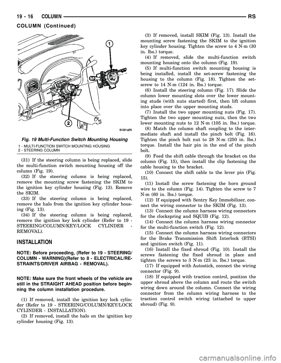
(31) If the steering column is being replaced, slide
the multi-function switch mounting housing off the
column (Fig. 19).
(32) If the steering column is being replaced,
remove the mounting screw fastening the SKIM to
the ignition key cylinder housing (Fig. 13). Remove
the SKIM.
(33) If the steering column is being replaced,
remove the halo from the ignition key cylinder hous-
ing (Fig. 13).
(34) If the steering column is being replaced,
remove the ignition key lock cylinder (Refer to 19 -
STEERING/COLUMN/KEY/LOCK CYLINDER -
REMOVAL).
INSTALLATION
NOTE: Before proceeding, (Refer to 19 - STEERING/
COLUMN - WARNING)(Refer to 8 - ELECTRICAL/RE-
STRAINTS/DRIVER AIRBAG - REMOVAL).
NOTE: Make sure the front wheels of the vehicle are
still in the STRAIGHT AHEAD position before begin-
ning the column installation procedure.
(1) If removed, install the ignition key lock cylin-
der (Refer to 19 - STEERING/COLUMN/KEY/LOCK
CYLINDER - INSTALLATION).
(2) If removed, install the halo on the ignition key
cylinder housing (Fig. 13).(3) If removed, install SKIM (Fig. 13). Install the
mounting screw fastening the SKIM to the ignition
key cylinder housing. Tighten the screw to 4 N´m (30
in. lbs.) torque.
(4) If removed, slide the multi-function switch
mounting housing onto the column (Fig. 19).
(5) If multi-function switch mounting housing is
being installed, install the set-screw fastening the
housing to the column (Fig. 18). Tighten the set-
screw to 14 N´m (124 in. lbs.) torque.
(6) Install the steering column (Fig. 17). Slide the
column lower mounting slots over the lower mount-
ing studs (with nuts started) first, then lift column
into place over the upper mounting studs.
(7) Install the two upper mounting nuts (Fig. 17).
Tighten the two upper mounting nuts, then the two
lower mounting nuts to 12 N´m (105 in. lbs.) torque.
(8) Match the column shaft coupling to the inter-
mediate shaft and install the pinch bolt (Fig. 16).
Tighten the pinch bolt nut to 28 N´m (250 in. lbs.)
torque. Install the hair pin in the end of the pinch
bolt.
(9) Feed the shift cable through the bracket on the
column (Fig. 15), then install the clip fastening the
cable housing to the bracket.
(10) Connect the shift cable to the lever pin (Fig.
15).
(11) Install the screw fastening the horn ground
wire to the column (Fig. 14). Tighten the screw to 7
N´m (60 in. lbs.) torque.
(12) If equipped with Sentry Key Immobilizer, con-
nect the wiring connector to the SKIM (Fig. 13).
(13) Connect the column harness wiring connectors
for the clockspring and SQUIB (Fig. 12).
(14) Connect the column harness wiring connector
for the multi-function switch (Fig. 12).
(15) Connect the column harness wiring connectors
for the Brake Transmission Shift Interlock (BTSI)
and ignition switch (Fig. 11).
(16) Install the fixed shroud (Fig. 10). Install the
screws fastening the fixed shroud in place and
tighten the screws to 3 N´m (23 in. lbs.) torque.
(17) If equipped with Autostick, connect the wiring
connector (Fig. 9).
(18) If equipped with traction control, position the
upper shroud above the column and route the switch
wiring down around the column. Connect the wiring
connector from the column wiring harness to the
traction control switch wiring (attached to upper
shroud) (Fig. 9).
Fig. 19 Multi-Function Switch Mounting Housing
1 - MULTI-FUNCTION SWITCH MOUNTING HOUSING
2 - STEERING COLUMN
19 - 16 COLUMNRS
COLUMN (Continued)
Page 1429 of 2339
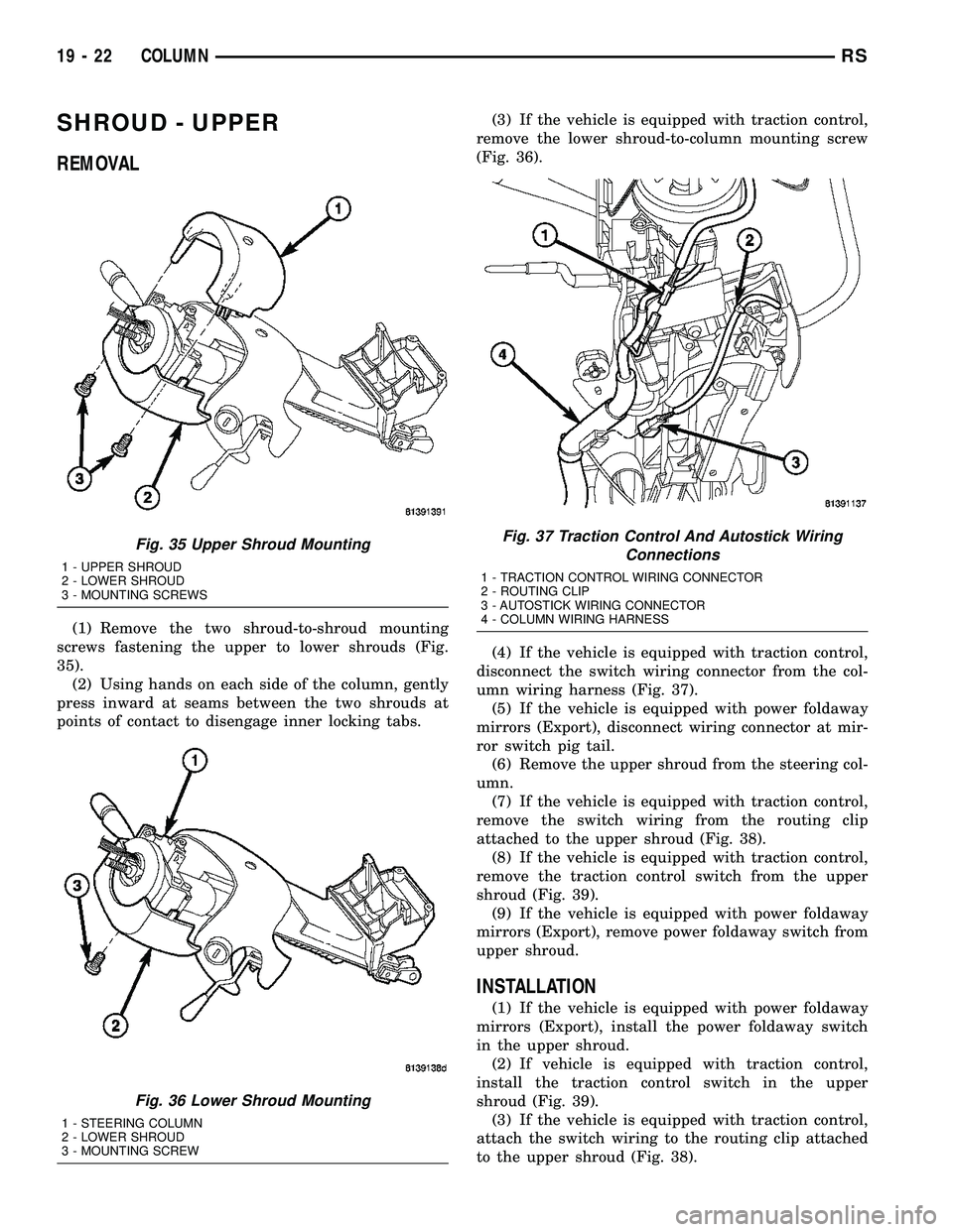
SHROUD - UPPER
REMOVAL
(1) Remove the two shroud-to-shroud mounting
screws fastening the upper to lower shrouds (Fig.
35).
(2) Using hands on each side of the column, gently
press inward at seams between the two shrouds at
points of contact to disengage inner locking tabs.(3) If the vehicle is equipped with traction control,
remove the lower shroud-to-column mounting screw
(Fig. 36).
(4) If the vehicle is equipped with traction control,
disconnect the switch wiring connector from the col-
umn wiring harness (Fig. 37).
(5) If the vehicle is equipped with power foldaway
mirrors (Export), disconnect wiring connector at mir-
ror switch pig tail.
(6) Remove the upper shroud from the steering col-
umn.
(7) If the vehicle is equipped with traction control,
remove the switch wiring from the routing clip
attached to the upper shroud (Fig. 38).
(8) If the vehicle is equipped with traction control,
remove the traction control switch from the upper
shroud (Fig. 39).
(9) If the vehicle is equipped with power foldaway
mirrors (Export), remove power foldaway switch from
upper shroud.
INSTALLATION
(1) If the vehicle is equipped with power foldaway
mirrors (Export), install the power foldaway switch
in the upper shroud.
(2) If vehicle is equipped with traction control,
install the traction control switch in the upper
shroud (Fig. 39).
(3) If the vehicle is equipped with traction control,
attach the switch wiring to the routing clip attached
to the upper shroud (Fig. 38).
Fig. 35 Upper Shroud Mounting
1 - UPPER SHROUD
2 - LOWER SHROUD
3 - MOUNTING SCREWS
Fig. 36 Lower Shroud Mounting
1 - STEERING COLUMN
2 - LOWER SHROUD
3 - MOUNTING SCREW
Fig. 37 Traction Control And Autostick Wiring
Connections
1 - TRACTION CONTROL WIRING CONNECTOR
2 - ROUTING CLIP
3 - AUTOSTICK WIRING CONNECTOR
4 - COLUMN WIRING HARNESS
19 - 22 COLUMNRS