2005 CHRYSLER CARAVAN service indicator
[x] Cancel search: service indicatorPage 1543 of 2339
FLUID
STANDARD PROCEDURE
FLUID LEVEL AND CONDITION CHECK
NOTE: Only transmission fluid of the type labeled
Mopar ATF+4 (Automatic Transmission Fluid)
should be used in this transaxle.
FLUID LEVEL CHECK
The transmission sump has a fluid level indicator
(dipstick) to check oil similar to most automatic
transmissions. It is located on the left side of the
engine. Be sure to wipe all dirt from dipstick handle
before removing.
The torque converter fills in both the P Park and N
Neutral positions. Place the selector lever in P Park
to be sure that the fluid level check is accurate.The
engine should be running at idle speed for at
least one minute, with the vehicle on level
ground.At normal operating temperature 82É C
(180É F), the fluid level is correct if it is in the HOT
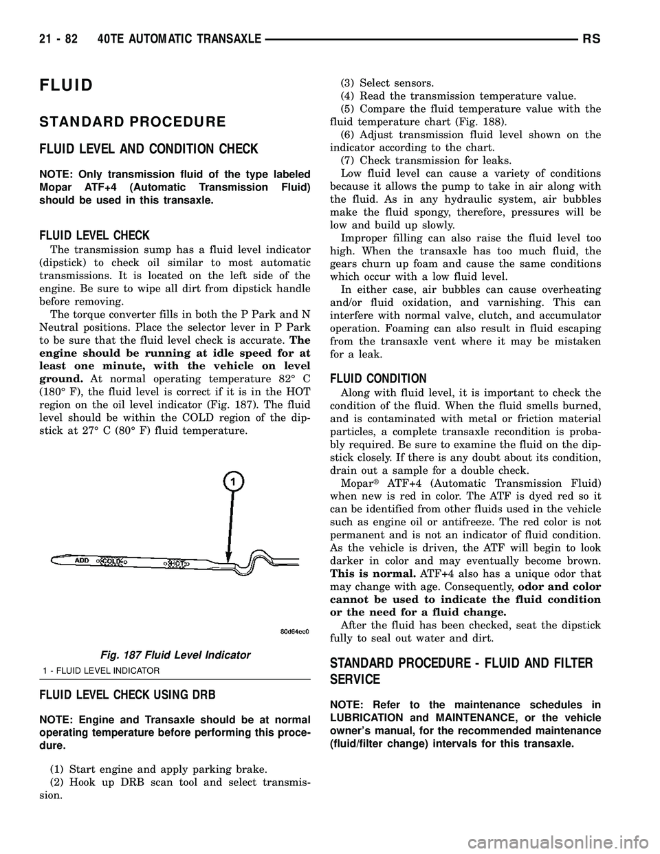
region on the oil level indicator (Fig. 187). The fluid
level should be within the COLD region of the dip-
stick at 27É C (80É F) fluid temperature.
FLUID LEVEL CHECK USING DRB
NOTE: Engine and Transaxle should be at normal
operating temperature before performing this proce-
dure.
(1) Start engine and apply parking brake.
(2) Hook up DRB scan tool and select transmis-
sion.(3) Select sensors.
(4) Read the transmission temperature value.
(5) Compare the fluid temperature value with the
fluid temperature chart (Fig. 188).
(6) Adjust transmission fluid level shown on the
indicator according to the chart.
(7) Check transmission for leaks.
Low fluid level can cause a variety of conditions
because it allows the pump to take in air along with
the fluid. As in any hydraulic system, air bubbles
make the fluid spongy, therefore, pressures will be
low and build up slowly.
Improper filling can also raise the fluid level too
high. When the transaxle has too much fluid, the
gears churn up foam and cause the same conditions
which occur with a low fluid level.
In either case, air bubbles can cause overheating
and/or fluid oxidation, and varnishing. This can
interfere with normal valve, clutch, and accumulator
operation. Foaming can also result in fluid escaping
from the transaxle vent where it may be mistaken
for a leak.
FLUID CONDITION
Along with fluid level, it is important to check the
condition of the fluid. When the fluid smells burned,
and is contaminated with metal or friction material
particles, a complete transaxle recondition is proba-
bly required. Be sure to examine the fluid on the dip-
stick closely. If there is any doubt about its condition,
drain out a sample for a double check.
MopartATF+4 (Automatic Transmission Fluid)
when new is red in color. The ATF is dyed red so it
can be identified from other fluids used in the vehicle
such as engine oil or antifreeze. The red color is not
permanent and is not an indicator of fluid condition.
As the vehicle is driven, the ATF will begin to look
darker in color and may eventually become brown.
This is normal.ATF+4 also has a unique odor that
may change with age. Consequently,odor and color
cannot be used to indicate the fluid condition
or the need for a fluid change.
After the fluid has been checked, seat the dipstick
fully to seal out water and dirt.
STANDARD PROCEDURE - FLUID AND FILTER
SERVICE
NOTE: Refer to the maintenance schedules in
LUBRICATION and MAINTENANCE, or the vehicle
owner's manual, for the recommended maintenance
(fluid/filter change) intervals for this transaxle.
Fig. 187 Fluid Level Indicator
1 - FLUID LEVEL INDICATOR
21 - 82 40TE AUTOMATIC TRANSAXLERS
Page 1545 of 2339
(6) Start engine and allow to idle for at least one
minute. Then, with parking and service brakes
applied, move selector lever momentarily to each
position, ending in the park or neutral position.
(7) Check the transaxle fluid level and add an
appropriate amount to bring the transaxle fluid level
to 3mm (1/8 in.) below the lowest mark on the dip-
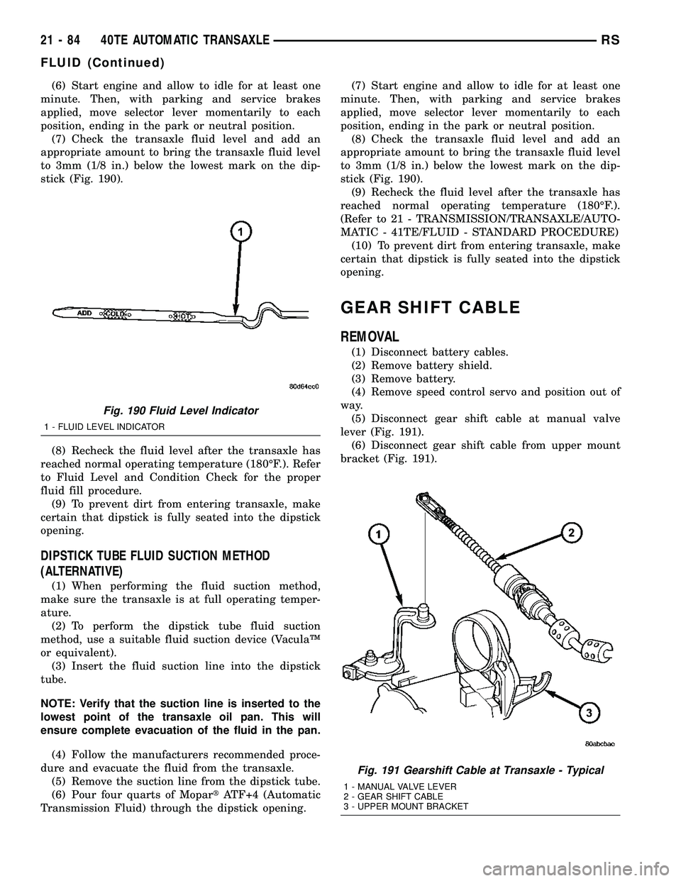
stick (Fig. 190).
(8) Recheck the fluid level after the transaxle has
reached normal operating temperature (180ÉF.). Refer
to Fluid Level and Condition Check for the proper
fluid fill procedure.
(9) To prevent dirt from entering transaxle, make
certain that dipstick is fully seated into the dipstick
opening.
DIPSTICK TUBE FLUID SUCTION METHOD
(ALTERNATIVE)
(1) When performing the fluid suction method,
make sure the transaxle is at full operating temper-
ature.
(2) To perform the dipstick tube fluid suction
method, use a suitable fluid suction device (VaculaŸ
or equivalent).
(3) Insert the fluid suction line into the dipstick
tube.
NOTE: Verify that the suction line is inserted to the
lowest point of the transaxle oil pan. This will
ensure complete evacuation of the fluid in the pan.
(4) Follow the manufacturers recommended proce-
dure and evacuate the fluid from the transaxle.
(5) Remove the suction line from the dipstick tube.
(6) Pour four quarts of MopartATF+4 (Automatic
Transmission Fluid) through the dipstick opening.(7) Start engine and allow to idle for at least one
minute. Then, with parking and service brakes
applied, move selector lever momentarily to each
position, ending in the park or neutral position.
(8) Check the transaxle fluid level and add an
appropriate amount to bring the transaxle fluid level
to 3mm (1/8 in.) below the lowest mark on the dip-
stick (Fig. 190).
(9) Recheck the fluid level after the transaxle has
reached normal operating temperature (180ÉF.).
(Refer to 21 - TRANSMISSION/TRANSAXLE/AUTO-
MATIC - 41TE/FLUID - STANDARD PROCEDURE)
(10) To prevent dirt from entering transaxle, make
certain that dipstick is fully seated into the dipstick
opening.
GEAR SHIFT CABLE
REMOVAL
(1) Disconnect battery cables.
(2) Remove battery shield.
(3) Remove battery.
(4) Remove speed control servo and position out of
way.
(5) Disconnect gear shift cable at manual valve
lever (Fig. 191).
(6) Disconnect gear shift cable from upper mount
bracket (Fig. 191).
Fig. 190 Fluid Level Indicator
1 - FLUID LEVEL INDICATOR
Fig. 191 Gearshift Cable at Transaxle - Typical
1 - MANUAL VALVE LEVER
2 - GEAR SHIFT CABLE
3 - UPPER MOUNT BRACKET
21 - 84 40TE AUTOMATIC TRANSAXLERS
FLUID (Continued)
Page 1650 of 2339
NOTE: The 2/4 Clutch Piston has bonded seals
which are not individually serviceable. Seal replace-
ment requires replacement of the piston assembly.
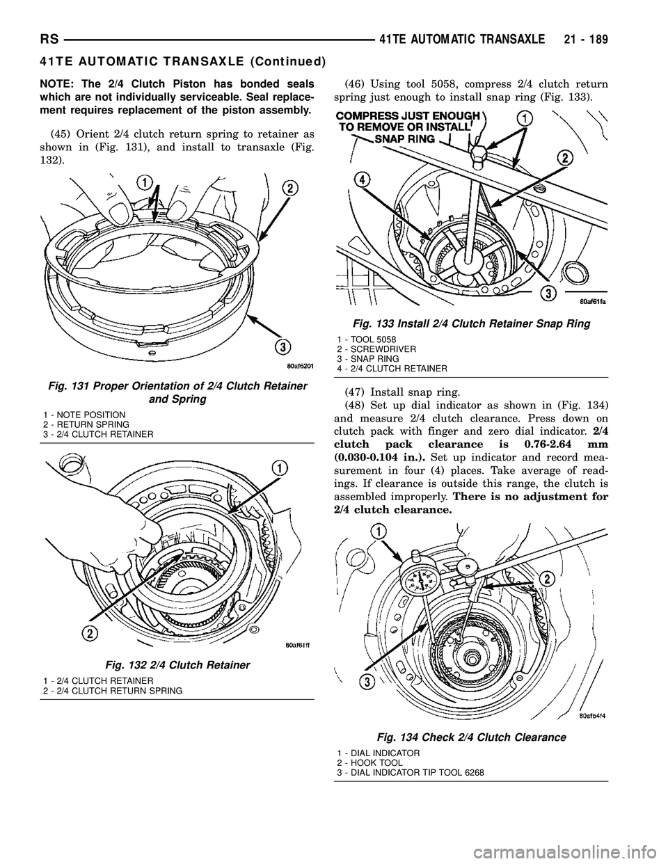
(45) Orient 2/4 clutch return spring to retainer as
shown in (Fig. 131), and install to transaxle (Fig.
132).(46) Using tool 5058, compress 2/4 clutch return
spring just enough to install snap ring (Fig. 133).
(47) Install snap ring.
(48) Set up dial indicator as shown in (Fig. 134)
and measure 2/4 clutch clearance. Press down on
clutch pack with finger and zero dial indicator.2/4
clutch pack clearance is 0.76-2.64 mm
(0.030-0.104 in.).Set up indicator and record mea-
surement in four (4) places. Take average of read-
ings. If clearance is outside this range, the clutch is
assembled improperly.There is no adjustment for
2/4 clutch clearance.
Fig. 131 Proper Orientation of 2/4 Clutch Retainer
and Spring
1 - NOTE POSITION
2 - RETURN SPRING
3 - 2/4 CLUTCH RETAINER
Fig. 132 2/4 Clutch Retainer
1 - 2/4 CLUTCH RETAINER
2 - 2/4 CLUTCH RETURN SPRING
Fig. 133 Install 2/4 Clutch Retainer Snap Ring
1 - TOOL 5058
2 - SCREWDRIVER
3 - SNAP RING
4 - 2/4 CLUTCH RETAINER
Fig. 134 Check 2/4 Clutch Clearance
1 - DIAL INDICATOR
2 - HOOK TOOL
3 - DIAL INDICATOR TIP TOOL 6268
RS41TE AUTOMATIC TRANSAXLE21 - 189
41TE AUTOMATIC TRANSAXLE (Continued)
Page 1692 of 2339
stick closely. If there is any doubt about its condition,
drain out a sample for a double check.
MopartATF+4 (Automatic Transmission Fluid)
when new is red in color. The ATF is dyed red so it
can be identified from other fluids used in the vehicle
such as engine oil or antifreeze. The red color is not
permanent and is not an indicator of fluid condition.
As the vehicle is driven, the ATF will begin to look
darker in color and may eventually become brown.
This is normal.ATF+4 also has a unique odor that
may change with age. Consequently,odor and color
cannot be used to indicate the fluid condition
or the need for a fluid change.
After the fluid has been checked, seat the dipstick
fully to seal out water and dirt.STANDARD PROCEDURE - FLUID AND FILTER
SERVICE
NOTE: Refer to the maintenance schedules in
LUBRICATION and MAINTENANCE, or the vehicle
owner's manual, for the recommended maintenance
(fluid/filter change) intervals for this transaxle.
NOTE: Only fluids of the type labeled MoparTATF+4
(Automatic Transmission Fluid) should be used. A
filter change should be made at the time of the
transmission oil change. The magnet (on the inside
of the oil pan) should also be cleaned with a clean,
dry cloth.
NOTE: If the transaxle is disassembled for any rea-
son, the fluid and filter should be changed.
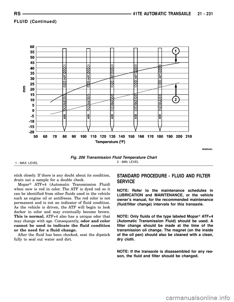
Fig. 206 Transmission Fluid Temperature Chart
1 - MAX. LEVEL2 - MIN. LEVEL
RS41TE AUTOMATIC TRANSAXLE21 - 231
FLUID (Continued)
Page 1693 of 2339
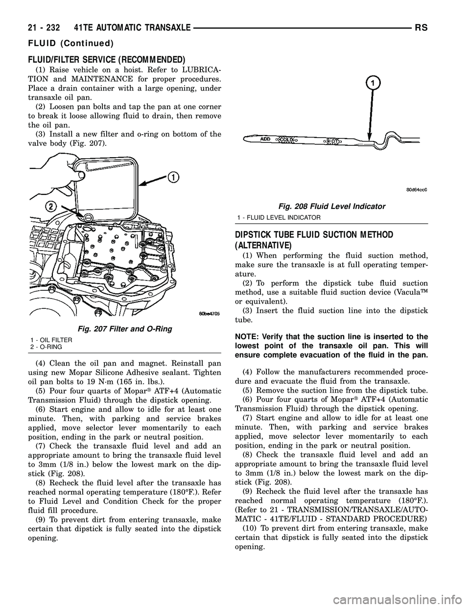
FLUID/FILTER SERVICE (RECOMMENDED)
(1) Raise vehicle on a hoist. Refer to LUBRICA-
TION and MAINTENANCE for proper procedures.
Place a drain container with a large opening, under
transaxle oil pan.
(2) Loosen pan bolts and tap the pan at one corner
to break it loose allowing fluid to drain, then remove
the oil pan.
(3) Install a new filter and o-ring on bottom of the
valve body (Fig. 207).
(4) Clean the oil pan and magnet. Reinstall pan
using new Mopar Silicone Adhesive sealant. Tighten
oil pan bolts to 19 N´m (165 in. lbs.).
(5) Pour four quarts of MopartATF+4 (Automatic
Transmission Fluid) through the dipstick opening.
(6) Start engine and allow to idle for at least one
minute. Then, with parking and service brakes
applied, move selector lever momentarily to each
position, ending in the park or neutral position.
(7) Check the transaxle fluid level and add an
appropriate amount to bring the transaxle fluid level
to 3mm (1/8 in.) below the lowest mark on the dip-
stick (Fig. 208).
(8) Recheck the fluid level after the transaxle has
reached normal operating temperature (180ÉF.). Refer
to Fluid Level and Condition Check for the proper
fluid fill procedure.
(9) To prevent dirt from entering transaxle, make
certain that dipstick is fully seated into the dipstick
opening.
DIPSTICK TUBE FLUID SUCTION METHOD
(ALTERNATIVE)
(1) When performing the fluid suction method,
make sure the transaxle is at full operating temper-
ature.
(2) To perform the dipstick tube fluid suction
method, use a suitable fluid suction device (VaculaŸ
or equivalent).
(3) Insert the fluid suction line into the dipstick
tube.
NOTE: Verify that the suction line is inserted to the
lowest point of the transaxle oil pan. This will
ensure complete evacuation of the fluid in the pan.
(4) Follow the manufacturers recommended proce-
dure and evacuate the fluid from the transaxle.
(5) Remove the suction line from the dipstick tube.
(6) Pour four quarts of MopartATF+4 (Automatic
Transmission Fluid) through the dipstick opening.
(7) Start engine and allow to idle for at least one
minute. Then, with parking and service brakes
applied, move selector lever momentarily to each
position, ending in the park or neutral position.
(8) Check the transaxle fluid level and add an
appropriate amount to bring the transaxle fluid level
to 3mm (1/8 in.) below the lowest mark on the dip-
stick (Fig. 208).
(9) Recheck the fluid level after the transaxle has
reached normal operating temperature (180ÉF.).
(Refer to 21 - TRANSMISSION/TRANSAXLE/AUTO-
MATIC - 41TE/FLUID - STANDARD PROCEDURE)
(10) To prevent dirt from entering transaxle, make
certain that dipstick is fully seated into the dipstick
opening.
Fig. 207 Filter and O-Ring
1 - OIL FILTER
2 - O-RING
Fig. 208 Fluid Level Indicator
1 - FLUID LEVEL INDICATOR
21 - 232 41TE AUTOMATIC TRANSAXLERS
FLUID (Continued)
Page 1767 of 2339
OPERATION
The Tire Pressure Monitoring (TPM) system uses
radio and sensor technology to monitor tire air pres-
sure levels. Sensors, mounted to each road wheel as
part of the valve stem, transmit a low frequency indi-
cating their individual pressure to a receiver located
in the Wireless Control Module (WCM) portion of the
Sentry Key Remote Electronic Entry Module
(SKREEM). These transmissions occur approximately
once every minute at speeds over 20 mph (32 km/h).
The Tire Pressure Monitoring system remains active
even if no tire pressure related message is displayed.
The sensors lay dormant (Park Mode), then wake
and start transmitting (Drive Mode) when the vehicle
first reaches speeds over 20 mph (32 km/h). Once the
wheels stop rotating for a period of approximately 30
minutes, the sensors shut down until again awaken.
Although not transmitting as when in Drive Mode,
while in Park Mode, the sensors still transmit
approximately once every 13 hours to let the receiver
know air pressure status at that time.
The receiver only receives information from the
four rotating tires. A fifth sensor may be located in
the spare tire wheel, depending on vehicle options.
Although this fifth sensor may be present, it does not
broadcast any information because it does not rotate.
When the system detects that a tire is going low,
below the Low Pressure (lamp) ON Threshold (See
following table), the driver is alerted to the situation.
The Base system illuminates an indicator lamp,
warning the driver of a pressure issue and sounds an
audible chime. In equipped with the Premium sys-
tem, the information is also displayed on the Elec-
tronic Vehicle Information Center (EVIC).
Once pressure in the suspect tire raises above the
Low Pressure (lamp) OFF Threshold, the lamp will
go out and the system returns to normal.
TPM THRESHOLD PRESSURES
DESCRIPTION SPECIFICATION
Placard Pressure (Cold) 36 PSI (248 kPa)
Low Pressure OFF Threshold 33 PSI (228 kPa)
Low Pressure ON Threshold 28 PSI (193 kPa)
SENSOR - TPM
DESCRIPTION
On vehicles equipped with Tire Pressure Monitor-
ing, one tire pressure sensor is mounted to each road
wheel (Fig. 18), and depending on factory wheel
options, a sensor may be located in the spare tire
wheel. Both aluminum and steel wheels are used in
this system, although sensors for one type wheel can-
not be used in the other type wheel.Each sensor has an internal battery that lasts up
to 10 years. The battery is not serviceable. At the
time of battery failure, the sensor must be replaced.
The serviceable components of the tire pressure sen-
sor are:
²Sensor-To-Wheel Grommet
²Valve Stem Cap
²Valve Stem Core
Valve stem caps and cores are specifically designed
for the tire pressure monitoring sensors. Although
similar to standard valve stem caps and cores, they
are different.
CAUTION: Do not use a standard valve stem cap or
core in a tire pressure sensor. Always use the orig-
inal equipment style sensor cap and core.
CAUTION: Do not reuse the Sensor-To-Wheel Grom-
met. Always use a new grommet when installing a
pressure sensor and properly torque the sensor
nut.
CAUTION: Do not attempt to install a tire pressure
sensor in an aftermarket wheel. Use only in original
style factory wheels.
OPERATION
The battery operated tire pressure sensors lay dor-
mant (Park Mode), then wake and start transmitting
(Drive Mode) when the vehicle first reaches speeds
over 20 mph (32 km/h). Once the wheels stop rotat-
ing for a period of approximately 30 minutes, the
sensors shut down until again awaken. Although not
transmitting as when in Drive Mode, while in Park
Mode, the sensors still transmit approximately once
every 13 hours to let the receiver know air pressure
status at that time.
Each sensor transmits tire pressure data approxi-
mately once every minute. Each sensor's (transmit-
ter) broadcast is uniquely coded so that the wireless
control module (WCM) can monitor the state of each
of the sensors on the four rotating road wheels. The
WCM (located in the SKREEM) automatically learns
and stores the sensor's ID while driving after a sen-
sor has been replaced. There is no retraining neces-
sary.
The receiver only receives information from the
four rotating tires. A fifth sensor may be located in
the spare tire wheel, depending on vehicle options.
Although this fifth sensor may be present, it does not
broadcast any information because it does not rotate.
For additional information, refer to Appropriate
Diagnostic Information.
22 - 10 TIRES/WHEELSRS
TIRE PRESSURE MONITORING (Continued)
Page 2302 of 2339
INDEX
ABS FASTENER TORQUE,SPECIFICATIONS ...................... 5-91
ABSORBER - DESCRIPTION, SHOCK .......2-36
ABSORBER - INSTALLATION, SHOCK ......2-38
ABSORBER - OPERATION, SHOCK ........2-36
ABSORBER - REMOVAL, SHOCK ..........2-36
ABSORBER (UPPER BUSHING) - ASSEMBLY, SHOCK .................... 2-37
ABSORBER (UPPER BUSHING) - DISASSEMBLY, SHOCK .................2-37
A/C CLUTCH BREAK-IN, STANDARD PROCEDURE ........................ 24-15
A/C COMPRESSOR CLUTCH COIL, DIAGNOSIS AND TESTING .............24-14
A/C COMPRESSOR CLUTCH RELAY - DESCRIPTION ....................... 24-18
A/C COMPRESSOR CLUTCH RELAY - INSTALLATION ....................... 24-19
A/C COMPRESSOR CLUTCH RELAY - OPERATION ......................... 24-18
A/C COMPRESSOR CLUTCH RELAY - REMOVAL .......................... 24-19
A/C COMPRESSOR CLUTCH/COIL - DESCRIPTION ....................... 24-13
A/C COMPRESSOR CLUTCH/COIL - OPERATION ......................... 24-13
A/C COMPRESSOR, DESCRIPTION .......24-72
A/C COMPRESSOR, INSTALLATION .......24-74
A/C COMPRESSOR MOUNTING BRACKET, 2.4L ENGINE ...........24-74,24-75
A/C COMPRESSOR NOISE DIAGNOSIS, DIAGNOSIS AND TESTING .............24-72
A/C COMPRESSOR, OPERATION .........24-72
A/C COMPRESSOR, REMOVAL ..........24-73
A/C CONDENSER - DESCRIPTION ........24-75
A/C CONDENSER - OPERATION ..........24-75
A/C COOL DOWN TEST, DIAGNOSIS AND TESTING ............................ 24-6
A/C DISCHARGE LINE - INSTALLATION . . . 24-80
A/C DISCHARGE LINE - REMOVAL .......24-79
A/C EVAPORATOR - DESCRIPTION . . 24-80,24-98
A/C EVAPORATOR - INSTALLATION ......24-81
A/C EVAPORATOR - OPERATION ....24-80,24-98
A/C EVAPORATOR - REMOVAL ..........24-81
A/C EVAPORATOR, INSTALLATION - REAR ............................. 24-100
A/C EVAPORATOR LINE EXTENSION, INSTALLATION - REAR ...............24-100
A/C EVAPORATOR LINE EXTENSION, REMOVAL - REAR .................... 24-99
A/C EVAPORATOR, REMOVAL - REAR .....24-98
A/C EXPANSION VALVE - DESCRIPTION . . 24-100
A/C EXPANSION VALVE - OPERATION ....24-100
A/C EXPANSION VALVE, DIAGNOSIS AND TESTING - FRONT .................... 24-82
A/C EXPANSION VALVE, DIAGNOSIS AND TESTING - REAR .................... 24-101
A/C HEATER CONTROL - DESCRIPTION . . . 24-19
A/C PERFORMANCE TEST, DIAGNOSIS AND TESTING ........................ 24-7
A/C PRESSURE TRANSDUCER - DESCRIPTION ....................... 24-20
A/C PRESSURE TRANSDUCER - OPERATION ......................... 24-20
A/C PRESSURE TRANSDUCER, DIAGNOSIS AND TESTING .............24-21
A/C SYSTEM - CAUTION ...............24-66
A/C SYSTEM, SPECIFICATIONS ..........24-11
A/C SYSTEM, WARNING ...............24-66
ACCELERATOR PEDAL - INSTALLATION . . . 14-28
ACCELERATOR PEDAL - REMOVAL .......14-28
ACCESSORY DRIVE BELT - DIAGNOSIS AND TESTING .........................7-7
ACCESSORY DRIVE BELT TENSION, SPECIFICATIONS .......................7-5
ACCUMULATOR - DESCRIPTION . . . 21-218,21-73
ACCUMULATOR - OPERATION ....21-218,21-73
A/C-HEATER CONTROL - DESCRIPTION . . . 24-33
A/C-HEATER CONTROL - INSTALLATION . . . 24-34
A/C-HEATER CONTROL - OPERATION .....24-33
A/C-HEATER CONTROL - REMOVAL ......24-33
A/C-HEATER CONTROL CALIBRATION, STANDARD PROCEDURE ...............24-19
ACTUATOR - DESCRIPTION, BLEND DOOR ........................ 24-22,24-34
ACTUATOR - DESCRIPTION, ENGAGE ......8N-9
ACTUATOR - DESCRIPTION, LATCH ......8N-13 ACTUATOR - DESCRIPTION, MODE
DOOR ............................. 24-29
ACTUATOR - DESCRIPTION, RECIRCULATION DOOR ................24-31
ACTUATOR - INSTALLATION, BLEND DOOR ........................ 24-22,24-35
ACTUATOR - INSTALLATION, ENGAGE ....8N-10
ACTUATOR - INSTALLATION, INSIDE HANDLE ............................ 23-27
ACTUATOR - INSTALLATION, LATCH .....8N-14
ACTUATOR - INSTALLATION, MODE DOOR ............................. 24-30
ACTUATOR - INSTALLATION, RECIRCULATION DOOR ................24-32
ACTUATOR - OPERATION, BLEND DOOR . . 24-22, 24-35
ACTUATOR - OPERATION, ENGAGE .......8N-9
ACTUATOR - OPERATION, LATCH ........8N-13
ACTUATOR - OPERATION, MODE DOOR . . . 24-29
ACTUATOR - OPERATION, RECIRCULATION DOOR ................24-31
ACTUATOR - REAR - DESCRIPTION, MODE DOOR ........................ 24-39
ACTUATOR - REAR - INSTALLATION, MODE DOOR ........................ 24-40
ACTUATOR - REAR - OPERATION, MODE DOOR ............................. 24-39
ACTUATOR - REAR - REMOVAL, MODE DOOR ............................. 24-39
ACTUATOR - REMOVAL, BLEND DOOR . . . 24-22, 24-35
ACTUATOR - REMOVAL, ENGAGE ..........8N-9
ACTUATOR - REMOVAL, INSIDE HANDLE . . 23-27
ACTUATOR - REMOVAL, LATCH .........8N-13
ACTUATOR - REMOVAL, MODE DOOR ....24-29
ACTUATOR - REMOVAL, RECIRCULATION DOOR ............................. 24-32
ADAPTER - INSTALLATION, FRONT DISC BRAKE CALIPER ...................... 5-31
ADAPTER - INSTALLATION, OIL FILTER . . . 9-142
ADAPTER - REMOVAL, FRONT DISC BRAKE CALIPER ...................... 5-31
ADAPTER - REMOVAL, OIL FILTER .......9-142
ADAPTIVE MEMORIES, OPERATION - FUEL CORRECTION OR ................14-24
ADDING ADDITIONAL COOLANT - STANDARD PROCEDURE .................7-4
ADDITIONAL COOLANT - STANDARD PROCEDURE, ADDING ...................7-4
ADHESIVE ATTACHED - INSTALLATION, EXTERIOR NAME PLATES ..............23-51
ADHESIVE ATTACHED - REMOVAL, EXTERIOR NAME PLATES ..............23-51
ADHESIVE LOCATIONS - FOLD-IN-FLOOR ONLY - SPECIFICATIONS,
STRUCTURAL ...................... 23-228
ADHESIVE LOCATIONS - SPECIFICATIONS, STRUCTURAL ........23-218
ADJUSTABLE - INSTALLATION, PEDALS ....5-43
ADJUSTABLE - REMOVAL, PEDALS .......5-40
ADJUSTABLE PEDALS SWITCH - INSTALLATION ........................ 5-11
ADJUSTABLE PEDALS SWITCH - REMOVAL ........................... 5-11
ADJUSTE R-BOR C-PILLAR -
INSTALLATION, SEAT BELT HEIGHT ......8O-38
ADJUSTE R-BOR C-PILLAR -
REMOVAL, SEAT BELT HEIGHT ..........8O-38
ADJUSTER - DIAGNOSIS AND TESTING, DRUM BRAKE AUTOMATIC ..............5-14
ADJUSTER - INSTALLATION, FRONT SEAT TRACK MANUAL ...............23-126
ADJUSTER - INSTALLATION, FRONT SEAT TRACK POWER ................23-124
ADJUSTER - REMOVAL, FRONT SEAT TRACK MANUAL .................... 23-125
ADJUSTER - REMOVAL, FRONT SEAT TRACK POWER ..................... 23-124
ADJUSTER KNOB - INSTALLATION, SEAT BELT HEIGHT ....................... 8O-38
ADJUSTER KNOB - REMOVAL, SEAT BELT HEIGHT ....................... 8O-38
ADJUSTER NOISE DIAGNOSIS - DIAGNOSIS AND TESTING, HYDRAULIC
LASH ............................... 9-34
ADJUSTER TENSION RELEASE - STANDARD PROCEDURE, PARKING
BRAKE AUTOMATIC .................... 5-63ADJUSTER TENSION RESET -
STANDARD PROCEDURE, PARKING
BRAKE AUTOMATIC .................... 5-64
ADJUSTER/MANUAL - OCS - INSTALLATION, FRONT SEAT TRACK ....23-128
ADJUSTER/MANUAL - OCS - REMOVAL, FRONT SEAT TRACK .................23-126
ADJUSTER/POWER - OCS - INSTALLATION, FRONT SEAT TRACK ....23-125
ADJUSTER/POWER - OCS - REMOVAL, FRONT SEAT TRACK .................23-124
ADJUSTERS - INSTALLATION, HYDRAULIC LASH ..................... 9-35
ADJUSTERS - REMOVAL, HYDRAULIC LASH ............................... 9-35
AERATION - DIAGNOSIS AND TESTING, COOLING SYSTEM .....................7-4
AFTER AN AIRBAG DEPLOYMENT - STANDARD PROCEDURE, SERVICE .......8O-7
AIR CLEANER ELEMENT - INSTALLATION . 9-101, 9-24
AIR CLEANER ELEMENT - REMOVAL . 9-101,9-24
AIR CLEANER HOUSING - INSTALLATION . 9-102, 9-25
AIR CLEANER HOUSING - REMOVAL . 9-101,9-25
AIR CONDITIONER, DESCRIPTION - HEATER ............................. 24-1
AIR CONDITIONER, OPERATION - HEATER ............................. 24-4
AIR CONTROL MOTOR - DESCRIPTION, IDLE ............................... 14-33
AIR CONTROL MOTOR - INSTALLATION, IDLE ............................... 14-33
AIR CONTROL MOTOR - OPERATION, IDLE ............................... 14-33
AIR CONTROL MOTOR - REMOVAL, IDLE . . 14-33
AIR EXHAUSTER - DESCRIPTION, REAR QUARTER PANEL/FENDER ..............23-59
AIR EXHAUSTER - INSTALLATION, REAR QUARTER PANEL/FENDER ..............23-60
AIR EXHAUSTER - REMOVAL, REAR QUARTER PANEL/FENDER ..............23-59
AIR FILTER - DESCRIPTION ............24-42
AIR FILTER - INSTALLATION ............24-43
AIR FILTER - REMOVAL ...............24-42
AIR GAP, SPECIFICATIONS - WHEEL SPEED SENSOR ....................... 5-91
AIR INTAKE PIPE - INSTALLATION ......24-115
AIR INTAKE PIPE - REMOVAL ..........24-115
AIR OUTLETS - DESCRIPTION .....24-43,24-56
AIR OUTLETS - INSTALLATION ..........24-56
AIR OUTLETS - REMOVAL .............24-56
AIR PRESSURE TESTS - DIAGNOSIS AND TESTING, CLUTCH ...........21-153,21-8
AIR TEMPERATURE SENSOR - DESCRIPTION, INLET .................14-34
AIRBAG - DESCRIPTION, CURTAIN .......8O-12
AIRBAG - DESCRIPTION, DRIVER ........8O-16
AIRBAG - DESCRIPTION, KNEE BLOCKER . 8O-22
AIRBAG - DESCRIPTION, PASSENGER ....8O-30
AIRBAG - INSTALLATION, CURTAIN ......8O-16
AIRBAG - INSTALLATION, DRIVER .......8O-18
AIRBAG - INSTALLATION, KNEE BLOCKER .......................... 8O-23
AIRBAG - INSTALLATION, PASSENGER . . . 8O-32
AIRBAG - OPERATION, CURTAIN ........8O-13
AIRBAG - OPERATION, DRIVER .........8O-16
AIRBAG - OPERATION, KNEE BLOCKER . . . 8O-22
AIRBAG - OPERATION, PASSENGER ......8O-30
AIRBAG - REMOVAL, CURTAIN ..........8O-14
AIRBAG - REMOVAL, DRIVER ...........8O-17
AIRBAG - REMOVAL, KNEE BLOCKER ....8O-23
AIRBAG - REMOVAL, PASSENGER .......8O-30
AIRBAG DEPLOYMENT - STANDARD PROCEDURE, SERVICE AFTER AN ........8O-7
AIRBAG DISABLED INDICATOR - DESCRIPTION, PASSENGER ............8O-33
AIRBAG DISABLED INDICATOR - INSTALLATION, PASSENGER ...........8O-34
AIRBAG DISABLED INDICATOR - OPERATION, PASSENGER ..............8O-33
AIRBAG DISABLED INDICATOR - REMOVAL, PASSENGER ...............8O-34
AIRBAG SYSTEM - DIAGNOSIS AND TESTING ............................ 8O-6
AIRBAGS - STANDARD PROCEDURE, HANDLING .......................... 8O-6
RS INDEX1
Description Group-Page Description Group-Page Description Group-Page
Page 2311 of 2339
DEFOGGER RELAY - DESCRIPTION,REAR WINDOW ....................... 8G-3
DEFOGGER RELAY - INSTALLATION, REAR WINDOW ....................... 8G-4
DEFOGGER RELAY - OPERATION, REAR WINDOW ............................ 8G-3
DEFOGGER RELAY - REMOVAL, REAR WINDOW ............................ 8G-4
DEFOGGER SWITCH - DESCRIPTION, REAR WINDOW ....................... 8G-4
DEFOGGER SWITCH - OPERATION, REAR WINDOW ............................ 8G-4
DEFROSTER DUCT - INSTALLATION ......24-50
DEFROSTER DUCT - REMOVAL ..........24-49
DEMAGNETIZING, STANDARD PROCEDURE - COMPASS ...............8M-5
DEMISTER DUCTS - INSTALLATION, INSTRUMENT PANEL .................. 24-54
DEMISTER DUCTS - REMOVAL, INSTRUMENT PANEL .................. 24-54
DEMISTER OUTLETS, INSTALLATION - FRONT ............................. 24-45
DEMISTER OUTLETS, REMOVAL - FRONT . 24-44
DEPLOYMENT - STANDARD PROCEDURE, SERVICE AFTER AN
AIRBAG ............................. 8O-7
DETECTION ASSY - INSTALLATION, NATURAL VAC LEAK .................. 25-14
DETECTION ASSY - REMOVAL, NATURAL VAC LEAK .......................... 25-14
DETECTION PUMP - INSTALLATION, LEAK .............................. 25-15
DETECTION PUMP - REMOVAL, LEAK ......25-15
DEVICES - STANDARD PROCEDURE, ELECTROSTATIC DISCHARGE (ESD)
SENSITIVE ........................8W -01-8
DIAGNOSTIC SYSTEM, DIAGNOSIS AND TESTING - ON-BOARD .................8F-22
DIAGNOSTIC TROUBLE CODES - STANDARD PROCEDURE, OBTAINING .....8E-15
DIAGRAMS - 4XTE TRANSAXLE HYDRAULIC SCHEMATICS,
SCHEMATICS .................. 21-199,21-54
DIAGRAMS - DESCRIPTION, HOW TO USE WIRING ......................8W -01-1
DIAGRAMS - SPECIAL TOOLS, SCHEMATICS ........................ 21-68
DIESEL - DESCRIPTION ...............19-52
DIESEL - INSTALLATION ...............19-53
DIESEL - REMOVAL ................... 19-52
DIESEL ENGINE - DESCRIPTION, FUEL REQUIREMENTS .......................0-6
DIESEL ENGINES - DESCRIPTION, ENGINE OIL ...........................0-6
DIESEL ENGINES - EXPORT - DESCRIPTION ........................ 0-21
DIESEL ENGINES, INSTALLATION - 2.5L/2.8L ........................... 24-78
DIESEL ENGINES, REMOVAL - 2.5L/2.8L . . 24-77
DIFFERENTIAL BEARING PRELOAD - ADJUSTMENT ...................... 21-228
DIFFERENTIAL BEARING PRELOAD MEASUREMENT AND ADJUSTMENT,
ADJUSTMENTS ...................... 21-79
DIMENSIONS - FOLD-IN-FLOOR SEATS ONLY - SPECIFICATIONS, FRAME ........13-11
DIMENSIONS - SPECIFICATIONS, BODY OPENING .......................... 23-180
DIMENSIONS - SPECIFICATIONS, FRAME . . . 13-6
DIODE - INSTALLATION ............8W-01-14
DIODE - REMOVAL ................8W -01-14
DISABLED INDICATOR - DESCRIPTION, PASSENGER AIRBAG .................8O-33
DISABLED INDICATOR - INSTALLATION, PASSENGER AIRBAG .................8O-34
DISABLED INDICATOR - OPERATION, PASSENGER AIRBAG .................8O-33
DISABLED INDICATOR - REMOVAL, PASSENGER AIRBAG .................8O-34
DISASSEMBLY/ASSEMBLY - STANDARD PROCEDURE, TRANSMISSION COOLER
LINE QUICK CONNECT FITTING ...........7-38
DISC BRAKE CALIPER - INSTALLATION, REAR ............................... 5-30
DISC BRAKE CALIPER - REMOVAL, REAR ............................... 5-28
DISC BRAKE CALIPER ADAPTER - INSTALLATION, FRONT .................5-31DISC BRAKE CALIPER ADAPTER -
REMOVAL, FRONT ..................... 5-31
DISC BRAKE CALIPER (CONTINENTAL TEVES BRAKES) - INSTALLATION,
FRONT .............................. 5-27
DISC BRAKE CALIPER (CONTINENTAL TEVES BRAKES) - REMOVAL, FRONT ......5-24
DISC BRAKE CALIPER GUIDE PINS (TRW BRAKES) - INSTALLATION ...............5-32
DISC BRAKE CALIPER GUIDE PINS (TRW BRAKES) - REMOVAL .................. 5-31
DISC BRAKE CALIPER (TRW BRAKES) - INSTALLATION, FRONT .................5-27
DISC BRAKE CALIPER (TRW BRAKES) - REMOVAL, FRONT ..................... 5-24
DISC BRAKE SHOES - CLEANING .....5-16,5-18
DISC BRAKE SHOES - INSPECTION . . . 5-16,5-18
DISC BRAKE SHOES - INSTALLATION, REAR ............................... 5-19
DISC BRAKE SHOES - REMOVAL, REAR ....5-17
DISC BRAKE SHOES (CONTINENTAL TEVES BRAKES) - INSTALLATION,
FRONT .............................. 5-16
DISC BRAKE SHOES (CONTINENTAL TEVES BRAKES) - REMOVAL, FRONT ......5-15
DISC BRAKE SHOES (TRW BRAKES) - INSTALLATION, FRONT .................5-17
DISC BRAKE SHOES (TRW BRAKES) - REMOVAL, FRONT ..................... 5-15
DISC BRAKES (EXPORT) - DESCRIPTION . . . 5-13
DISC BRAKES (FRONT) - DESCRIPTION ....5-11
DISC BRAKES (FRONT) - OPERATION ......5-13
DISC BRAKES (REAR) - DESCRIPTION .....5-13
DISC BRAKES (REAR) - OPERATION ......5-14
DISCHARGE (ESD) SENSITIVE DEVICES - STANDARD PROCEDURE,
ELECTROSTATIC ...................8W -01-8
DISCHARGE LINE - INSTALLATION, A/C . . . 24-80
DISCHARGE LINE - REMOVAL, A/C .......24-79
DISPLAY - DESCRIPTION, PARK ASSIST . . . 8B-3
DISPLAY - INSTALLATION, PARK ASSIST . . . 8B-4
DISPLAY - OPERATION, PARK ASSIST .....8B-3
DISPLAY - REMOVAL, PARK ASSIST ......8B-4
DISPLAY TEST MODE, OPERATION - DRB III T STATE .......................... 25-10
DISSASEMBLY, REMOVAL ..............24-51
DISTRIBUTION DUCT - INSTALLATION ....24-57
DISTRIBUTION DUCT - REMOVAL ........24-57
DISTRIBUTION DUCTS - INSTALLATION, FLOOR ............................. 24-50
DISTRIBUTION DUCTS - REMOVAL, FLOOR ............................. 24-50
DISTRIBUTION SYSTEM - DESCRIPTION, POWER ..........................8W -97-1
DISTRIBUTION SYSTEM - OPERATION, POWER ..........................8W -97-1
DISTRIBUTION SYSTEMS, SPECIAL TOOLS - POWER ...................8W -97-1
DOES NOT FILL - DIAGNOSIS AND TESTING, VEHICLE ................... 25-17
DOME/CARGO LAMP - INSTALLATION ....8L-22
DOME/CARGO LAMP - REMOVAL ........8L-22
DOOR - INSTALLATION ................23-15
DOOR - INSTALLATION, FUEL FILL .......23-52
DOOR - INSTALLATION, SLIDING ........23-29
DOOR - REMOVAL .................... 23-15
DOOR - REMOVAL, FUEL FILL ..........23-52
DOOR - REMOVAL, SLIDING ............23-29
DOOR ACTUATOR - DESCRIPTION, BLEND ........................ 24-22,24-34
DOOR ACTUATOR - DESCRIPTION, MODE ............................. 24-29
DOOR ACTUATOR - DESCRIPTION, RECIRCULATION ..................... 24-31
DOOR ACTUATOR - INSTALLATION, BLEND ........................ 24-22,24-35
DOOR ACTUATOR - INSTALLATION, MODE ............................. 24-30
DOOR ACTUATOR - INSTALLATION, RECIRCULATION ..................... 24-32
DOOR ACTUATOR - OPERATION, BLEND . . 24-22,
24-35
DOOR ACTUATOR - OPERATION, MODE . . . 24-29
DOOR ACTUATOR - OPERATION, RECIRCULATION ..................... 24-31
DOOR ACTUATOR - REAR - DESCRIPTION, MODE .................24-39DOOR ACTUATOR - REAR -
INSTALLATION, MODE .................24-40
DOOR ACTUATOR - REAR - OPERATION, MODE ............................. 24-39
DOOR ACTUATOR - REAR - REMOVAL, MODE ............................. 24-39
DOOR ACTUATOR - REMOVAL, BLEND . . . 24-22, 24-35
DOOR ACTUATOR - REMOVAL, MODE ....24-29
DOOR ACTUATOR - REMOVAL, RECIRCULATION ..................... 24-32
DOOR ADJUSTMENT, STANDARD PROCEDURE - POWER SLIDING .........8N-49
DOOR ADJUSTMENTS, ADJUSTMENTS - SLIDING ............................ 23-30
DOOR BLOCKER LATCH - INSTALLATION, FUEL FILL .......................... 23-53
DOOR BLOCKER LATCH - REMOVAL, FUEL FILL .......................... 23-53
DOOR BLOCKER LATCH STRIKER - INSTALLATION, FUEL FILL .............23-53
DOOR BLOCKER LATCH STRIKER - REMOVAL, FUEL FILL .................23-53
DOOR BLOCKER LOCKOUT LINK - INSTALLATION, FUEL FILL .............23-54
DOOR BLOCKER LOCKOUT LINK - REMOVAL, FUEL FILL .................23-54
DOOR CONTROL MODULE - DESCRIPTION, SLIDING ...............8E-18
DOOR CONTROL MODULE - OPERATION, SLIDING ............................ 8E-18
DOOR CONTROL MODULE, DIAGNOSIS AND TESTING - SLIDING ...............8E-18
DOOR CYLINDER LOCK SWITCH - EXPORT - DESCRIPTION ...............8N-22
DOOR CYLINDER LOCK SWITCH - EXPORT - OPERATION ................8N-22
DOOR CYLINDER LOCK SWITCH, EXPORT ............................ 8N-22
DOOR GLASS - INSTALLATION ..........23-17
DOOR GLASS - INSTALLATION, SLIDING . 23-163
DOOR GLASS - REMOVAL .............23-16
DOOR GLASS - REMOVAL, SLIDING .....23-163
DOOR GLASS RUN WEATHERSTRIP - INSTALLATION, FRONT ...............23-166
DOOR GLASS RUN WEATHERSTRIP - REMOVAL, FRONT ................... 23-166
DOOR INNER BELT MOLDING - INSTALLATION, FRONT ...............23-168
DOOR INNER BELT MOLDING - REMOVAL, FRONT ................... 23-168
DOOR LEARN CYCLE, STANDARD PROCEDURE - POWER SLIDING .........8N-48
DOOR LOCK MOTOR - INSTALLATION, SLIDING ........................... 8N-25
DOOR LOCK MOTOR - REMOVAL, SLIDING ........................... 8N-25
DOOR LOCK MOTOR, DIAGNOSIS AND TESTING ........................... 8N-23
DOOR LOCK SWITCH, DIAGNOSIS AND TESTING ........................... 8N-23
DOOR MOTOR - DESCRIPTION, SLIDING . . 8N-51
DOOR MOTOR - INSTALLATION, SLIDING . 8N-51
DOOR MOTOR - OPERATION, SLIDING . . . 8N-51
DOOR MOTOR - REMOVAL, SLIDING .....8N-51
DOOR OUTER BELT MOLDING - INSTALLATION, FRONT ...............23-167
DOOR OUTER BELT MOLDING - REMOVAL, FRONT ................... 23-167
DOOR SILL PLATE - INSTALLATION, SLIDING ............................ 23-99
DOOR SILL PLATE - REMOVAL, SLIDING . . 23-98
DOOR SILL TRIM PLATE - INSTALLATION ....................... 23-89
DOOR SILL TRIM PLATE - REMOVAL .....23-89
DOOR STOP BUMPER BEZEL - INSTALLATION, SLIDING ...............23-25
DOOR STOP BUMPER BEZEL - REMOVAL, SLIDING .................. 23-25
DOOR SYSTEM - DESCRIPTION, POWER SLIDING ........................... 8N-40
DOOR SYSTEM - OPERATION, POWER SLIDING ........................... 8N-41
DOOR SYSTEM, DIAGNOSIS AND TESTING - POWER SLIDING ............8N-42
DOOR WEATHERSTRIP - INSTALLATION, FRONT ............................ 23-168
10 INDEXRS
Description Group-Page Description Group-Page Description Group-Page