2005 CHRYSLER CARAVAN change wheel
[x] Cancel search: change wheelPage 556 of 2339

OPERATION
When rear wiper operation is required, the BCM
will provide ignition ON voltage to the rear wiper
motor. When the wiper switch is turned OFF, the
BCM provides circuit ground to operate the motor
until the wipe cycle is complete and the wiper arm
returns to the base of the rear window.
The rear wiper/washer switch only offers an inter-
mittent rear wiper mode. The wiper motor will cycle
every 7 seconds. The intermittent delay time is also
adjusted based upon vehicle speed. With the vehicle
traveling greater than 50 mph, the cycle changes to
every 5 seconds.
When rear washer is requested by depressing and
holding down the switch, the BCM then provides a
ground for the rear washer motor. Until the switch is
released, the motor will be in a continuous wipe
mode, then return to an intermittent wipe mode.
WASHER FLUID LEVEL
SWITCH
REMOVAL
(1) Disconnect and isolate the battery negative
cable.
(2) Hoist and support vehicle on hoist or jack
stands.
(3) If necessary, remove the right front wheel and
tire assembly (Refer to 22 - TIRES/WHEELS -
REMOVAL).
(4) Disconnect the right front wheelhouse splash
shield and move aside (Refer to 23 - BODY/EXTERI-
OR/WHEELHOUSE SPLASH SHIELD - REMOVAL).
(5) Drain washer fluid from the reservoir and into
a suitable clean container. This can be done by dis-connecting the windshield washer hose from the
front (outboard) washer pump port allowing the
washer fluid to drain into a container through a tem-
porary jumper hose connected to the front washer
pump.
(6) Disconnect the electrical body harness connec-
tor to the the fluid level sensor. Slide the red lock on
the connector to the release position, then, depress
the black tab and pull the connector off the sensor.
(7) Remove the sensor from reservoir by using a
side foot to gently pry the sensor from the body of
the reservoir. Do not damage the reservoir/sensor
sealing surface or puncture reservoir during removal.
CAUTION: To avoid damage to the sensor, assure
the reservoir is in an upright position before remov-
ing the sensor from the reservoir. Do not rotate the
sensor during removal.
INSTALLATION
(1) Use a new grommet when installing a new sen-
sor assembly.
(2) Assure that the flat of the sensor is aligned
under the ridge of the reservoir and that the sensor
connector is facing down in the fully seated position.
This will allow for proper operation of the sensor
float switch.
(3) Connect the electrical body harness connectors
to the fluid level sensor. Slide the red lock on the
connector to the closed or locked position.
(4) Assure that washer hose is properly routed to
prevent pinching and possible inoperative washers.
(5) Connect the left right front wheelhouse splash
shield and move aside (Refer to 23 - BODY/EXTERI-
OR/WHEELHOUSE SPLASH SHIELD - INSTALLA-
TION).
(6) Install the right front wheel and tire assembly
(Refer to 22 - TIRES/WHEELS - INSTALLATION).
(7) lower vehicle from hoist or jack stands.
(8) Connect the battery negative cable.
(9) Verify system operation.
WASHER HOSES
REMOVAL
(1) Remove washer reservoir from vehicle (Refer to
8 - ELECTRICAL/WIPERS/WASHERS/WASHER
RESERVOIR - REMOVAL).
(2) Disconnect washer hose front the reservoir cav-
ity.
(3) Disconnect the washer hose from the reservoir
pump.
(4) Remove parts as necessary to replace washer
hose (engine compartment, interior components, etc.).
Fig. 4 REAR WIPER/WASHER SWITCH LOCATION
1 - REAR WIPER/WASHER SWITCH
2 - HVAC CONTROL UNIT
RSWIPERS/WASHERS8R-11
REAR WIPER/WASHER SWITCH (Continued)
Page 1184 of 2339
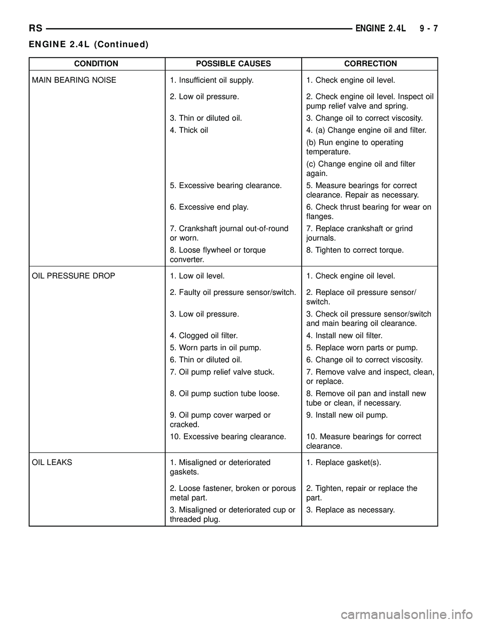
CONDITION POSSIBLE CAUSES CORRECTION
MAIN BEARING NOISE 1. Insufficient oil supply. 1. Check engine oil level.
2. Low oil pressure. 2. Check engine oil level. Inspect oil
pump relief valve and spring.
3. Thin or diluted oil. 3. Change oil to correct viscosity.
4. Thick oil 4. (a) Change engine oil and filter.
(b) Run engine to operating
temperature.
(c) Change engine oil and filter
again.
5. Excessive bearing clearance. 5. Measure bearings for correct
clearance. Repair as necessary.
6. Excessive end play. 6. Check thrust bearing for wear on
flanges.
7. Crankshaft journal out-of-round
or worn.7. Replace crankshaft or grind
journals.
8. Loose flywheel or torque
converter.8. Tighten to correct torque.
OIL PRESSURE DROP 1. Low oil level. 1. Check engine oil level.
2. Faulty oil pressure sensor/switch. 2. Replace oil pressure sensor/
switch.
3. Low oil pressure. 3. Check oil pressure sensor/switch
and main bearing oil clearance.
4. Clogged oil filter. 4. Install new oil filter.
5. Worn parts in oil pump. 5. Replace worn parts or pump.
6. Thin or diluted oil. 6. Change oil to correct viscosity.
7. Oil pump relief valve stuck. 7. Remove valve and inspect, clean,
or replace.
8. Oil pump suction tube loose. 8. Remove oil pan and install new
tube or clean, if necessary.
9. Oil pump cover warped or
cracked.9. Install new oil pump.
10. Excessive bearing clearance. 10. Measure bearings for correct
clearance.
OIL LEAKS 1. Misaligned or deteriorated
gaskets.1. Replace gasket(s).
2. Loose fastener, broken or porous
metal part.2. Tighten, repair or replace the
part.
3. Misaligned or deteriorated cup or
threaded plug.3. Replace as necessary.
RSENGINE 2.4L9-7
ENGINE 2.4L (Continued)
Page 1260 of 2339
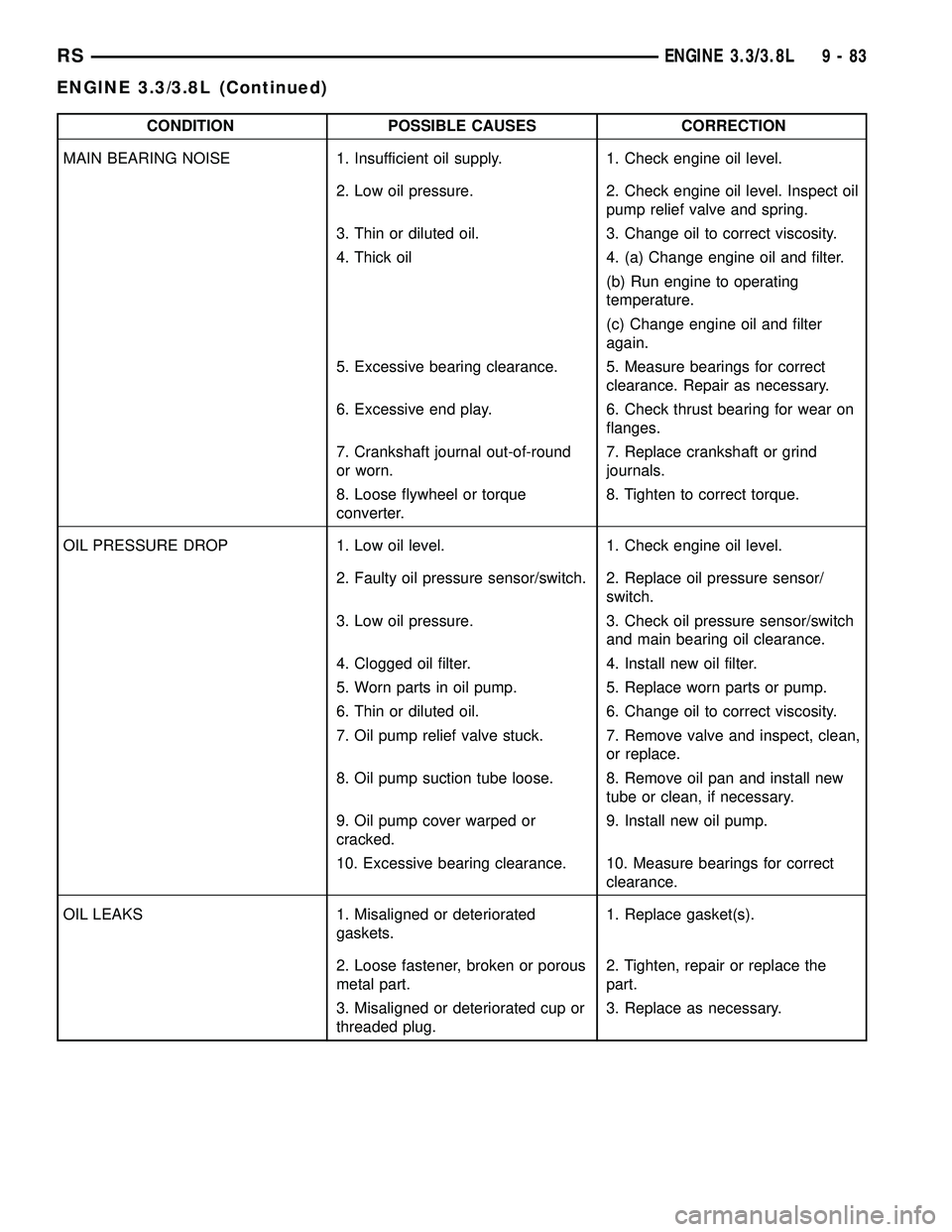
CONDITION POSSIBLE CAUSES CORRECTION
MAIN BEARING NOISE 1. Insufficient oil supply. 1. Check engine oil level.
2. Low oil pressure. 2. Check engine oil level. Inspect oil
pump relief valve and spring.
3. Thin or diluted oil. 3. Change oil to correct viscosity.
4. Thick oil 4. (a) Change engine oil and filter.
(b) Run engine to operating
temperature.
(c) Change engine oil and filter
again.
5. Excessive bearing clearance. 5. Measure bearings for correct
clearance. Repair as necessary.
6. Excessive end play. 6. Check thrust bearing for wear on
flanges.
7. Crankshaft journal out-of-round
or worn.7. Replace crankshaft or grind
journals.
8. Loose flywheel or torque
converter.8. Tighten to correct torque.
OIL PRESSURE DROP 1. Low oil level. 1. Check engine oil level.
2. Faulty oil pressure sensor/switch. 2. Replace oil pressure sensor/
switch.
3. Low oil pressure. 3. Check oil pressure sensor/switch
and main bearing oil clearance.
4. Clogged oil filter. 4. Install new oil filter.
5. Worn parts in oil pump. 5. Replace worn parts or pump.
6. Thin or diluted oil. 6. Change oil to correct viscosity.
7. Oil pump relief valve stuck. 7. Remove valve and inspect, clean,
or replace.
8. Oil pump suction tube loose. 8. Remove oil pan and install new
tube or clean, if necessary.
9. Oil pump cover warped or
cracked.9. Install new oil pump.
10. Excessive bearing clearance. 10. Measure bearings for correct
clearance.
OIL LEAKS 1. Misaligned or deteriorated
gaskets.1. Replace gasket(s).
2. Loose fastener, broken or porous
metal part.2. Tighten, repair or replace the
part.
3. Misaligned or deteriorated cup or
threaded plug.3. Replace as necessary.
RSENGINE 3.3/3.8L9-83
ENGINE 3.3/3.8L (Continued)
Page 1408 of 2339
STEERING
TABLE OF CONTENTS
page page
STEERING
DESCRIPTION - POWER STEERING SYSTEM . . 1
OPERATION - POWER STEERING SYSTEM . . . 1
DIAGNOSIS AND TESTING
DIAGNOSIS AND TESTING - POWER
STEERING SYSTEM FLOW AND
PRESSURE TEST......................1
DIAGNOSIS AND TESTING - STEERING
SYSTEM DIAGNOSIS CHARTS............3SPECIFICATIONS
POWER STEERING FASTENER TORQUE . . . 9
SPECIAL TOOLS
POWER STEERING....................9
COLUMN..............................10
GEAR.................................26
PUMP.................................36
STEERING
DESCRIPTION - POWER STEERING SYSTEM
This vehicle comes with power steering as stan-
dard equipment. The power steering system consists
of these major components:
²POWER STEERING PUMP
²POWER STEERING GEAR
²POWER STEERING FLUID
²POWER STEERING FLUID COOLER (If
Equipped)
²POWER STEERING FLUID RESERVOIR
²POWER STEERING FLUID SUPPLY HOSE
²POWER STEERING FLUID PRESSURE HOSE
²POWER STEERING FLUID RETURN HOSE
For information on the first two components, refer
to their respective sections within this service man-
ual group. Information on all other components can
be found in POWER STEERING PUMP.
OPERATION - POWER STEERING SYSTEM
Turning of the steering wheel is converted into lin-
ear (side-to-side) travel through the meshing of the
helical pinion teeth with the rack teeth within the
steering gear. The lateral travel pushes and pulls the
tie rods to change the direction of the vehicle's front
wheels.
Power assist steering is provided by a belt driven
rotary type pump. It directs fluid through power
steering fluid hoses to the power steering gear where
it is used to assist the driver's turning effort.
Manual steering control of the vehicle can be main-
tained if power steering assist is lost. However,
under this condition, steering effort is significantly
increased.
DIAGNOSIS AND TESTING
DIAGNOSIS AND TESTING - POWER STEERING
SYSTEM FLOW AND PRESSURE TEST
ALL ENGINES
The following procedure is to be used to test the
operation of the power steering system on this vehi-
cle. This test will provide the flow rate of the power
steering pump along with the maximum relief pres-
sure. This test is to be performed to determine if the
power steering pump or power steering gear is not
functioning properly. The following flow and pressure
test is performed using the Power Steering Analyzer
Kit, Special Tool 6815 (Fig. 1), hoses, Special Tools
6905 and 6959, and fittings from adapter kit, Special
Tool 6893.
Fig. 1 Power Steering Analyzer With Hoses Installed
1 - OUTLET
2 - SPECIAL TOOL 6815
3 - INLET
RSSTEERING19-1
Page 1433 of 2339
GEAR
TABLE OF CONTENTS
page page
GEAR
DESCRIPTION.........................26
OPERATION...........................26
WARNING
WARNINGS AND CAUTIONS.............26
REMOVAL
REMOVAL - LHD GEAR.................26
REMOVAL - RHD GEAR................29INSTALLATION
INSTALLATION - LHD GEAR.............31
INSTALLATION - RHD GEAR.............33
SPECIAL TOOLS
POWER STEERING GEAR..............34
OUTER TIE ROD
REMOVAL.............................34
INSTALLATION.........................35
GEAR
DESCRIPTION
This vehicle is equipped with a rack and pinion
power steering gear (Fig. 1). It is mounted to the
underside of the front suspension cradle/crossmem-
ber.
The steering column is attached to the gear
through the use of an intermediate shaft and cou-
plers. The outer ends of the power steering gear's
outer tie rods connect to the steering knuckles.
NOTE: The power steering gear should NOT be ser-
viced or adjusted unless DaimlerChrysler Corpora-
tion authorizes. If a malfunction or oil leak occurs,
the complete steering gear should be replaced.
Only the outer tie rods may be replaced separately
from the rest of the gear.
OPERATION
Turning of the steering wheel is converted into lin-
ear (side-to-side) travel through the meshing of the
helical pinion teeth with the rack teeth in the steer-
ing gear. This travel pushes and pulls the tie rods to
change the direction of the vehicle's front wheels.
Power assist steering provided by the power steer-
ing pump is controlled by an open center, rotary type
control valve which directs oil from the pump to
either side of the integral rack piston upon demand.
Road feel is controlled by the diameter of a torsion
bar which initially steers the vehicle. As required
steering effort increases, as in a turn, the torsion bar
twists, causing relative rotary motion between the
rotary valve body and the valve spool. This move-
ment directs oil behind the integral rack piston
which, in turn, builds hydraulic pressure and assists
in the turning effort.Manual steering control of the vehicle can be main-
tained if power steering assist is lost. However,
under this condition, steering effort is significantly
increased.
WARNING
WARNINGS AND CAUTIONS
WARNING: POWER STEERING FLUID, ENGINE
PARTS AND EXHAUST SYSTEM MAY BE
EXTREMELY HOT IF ENGINE HAS BEEN RUNNING.
DO NOT START ENGINE WITH ANY LOOSE OR DIS-
CONNECTED HOSES. DO NOT ALLOW HOSES TO
TOUCH HOT EXHAUST MANIFOLD OR CATALYST.
WARNING: FLUID LEVEL SHOULD BE CHECKED
WITH THE ENGINE OFF TO PREVENT PERSONAL
INJURY FROM MOVING PARTS.
CAUTION: When the system is open, cap all open
ends of the hoses, power steering pump fittings or
power steering gear ports to prevent entry of for-
eign material into the components.
REMOVAL
REMOVAL - LHD GEAR
(1) Remove cap from power steering fluid reser-
voir.
(2) Using a siphon pump, remove as much fluid as
possible from the power steering fluid reservoir.Use
care not to damage the filter mesh below the
fluid surface.
19 - 26 GEARRS
Page 1768 of 2339
CAUTION
CAUTION: The use of tire sealants is strictly prohib-
ited for vehicles equipped with the Tire Pressure
Monitoring system. Tire sealants can clog tire pres-
sure sensors.
CAUTION: Tire pressure sensor valve stem caps
and cores are specially designed for the sensors.
Due to risk of corrosion, do not use a standard
valve stem cap or core in a tire pressure sensor in
place of the original equipment style sensor cap
and core.
CAUTION: Do not attempt to install a tire pressure
sensor in a steel wheel or aftermarket wheel. Use
tire pressure sensors in original style factory
wheels only.
NOTE: TPM thresholds have been established for
the original tire size equipped on the vehicle. Use
original size tires only to maintain system accuracy.
DIAGNOSIS AND TESTING - TIRE PRESSURE
SENSOR
NOTE: Tire pressure may increase from 2 to 6 psi
(14 to 41 kPa) during normal driving conditions. Do
NOT reduce this normal pressure build up.
If a fault in the system is detected, always check
air pressure in the tires first with a known accurate
air gauge and correct the inflation pressure. If any
tire is low, inspectallthe tires.
If the gauge-read pressure in the tires does not
indicate a tire pressure issue, refer to the appropri-
ate diagnostic information.
REMOVAL
(1) Remove tire and wheel assembly from vehicle.
(Refer to 22 - TIRES/WHEELS - REMOVAL)
CAUTION: The cap used on this valve stem con-
tains an O-ring seal to prevent contamination and
moisture from entering the valve stem. Retain this
valve stem cap for reuse. Do not substitute a regu-
lar valve stem cap in its place.
CAUTION: The valve stem used on this vehicle is
made of aluminum and the core is nickel plated
brass. The original valve stem core must be rein-
stalled and not substituted with a valve stem core
made of a different material. This is required to pre-
vent corrosion in the valve stem caused by the dif-
ferent metals.(2) Dismount tire from wheel following tire
changer manufacturers instructions while paying
special attention to the following to avoid damaging
the pressure sensor:
(a) When breaking the tire bead loose from the
wheel rim, avoid using the Bead Breaker in the
area of the sensor. That includes both front and
rear beads of the tire.
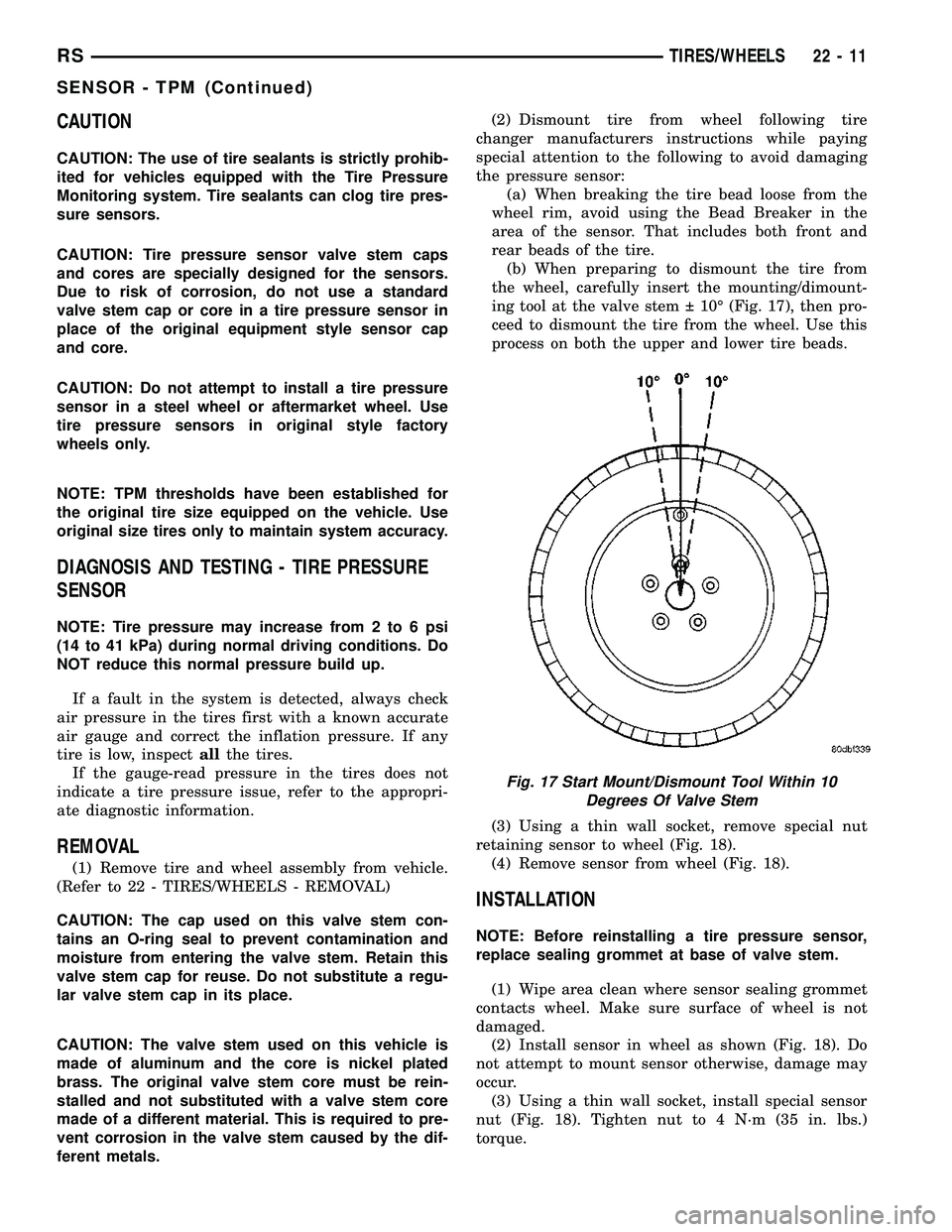
(b) When preparing to dismount the tire from
the wheel, carefully insert the mounting/dimount-
ing tool at the valve stem 10É (Fig. 17), then pro-
ceed to dismount the tire from the wheel. Use this
process on both the upper and lower tire beads.
(3) Using a thin wall socket, remove special nut
retaining sensor to wheel (Fig. 18).
(4) Remove sensor from wheel (Fig. 18).
INSTALLATION
NOTE: Before reinstalling a tire pressure sensor,
replace sealing grommet at base of valve stem.
(1) Wipe area clean where sensor sealing grommet
contacts wheel. Make sure surface of wheel is not
damaged.
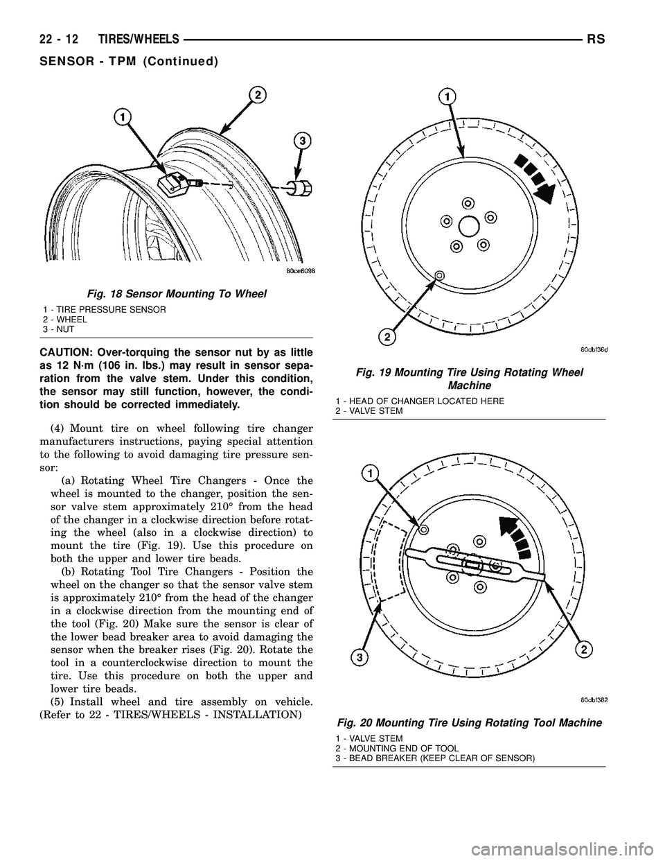
(2) Install sensor in wheel as shown (Fig. 18). Do
not attempt to mount sensor otherwise, damage may
occur.
(3) Using a thin wall socket, install special sensor
nut (Fig. 18). Tighten nut to 4 N´m (35 in. lbs.)
torque.
Fig. 17 Start Mount/Dismount Tool Within 10
Degrees Of Valve Stem
RSTIRES/WHEELS22-11
SENSOR - TPM (Continued)
Page 1769 of 2339
CAUTION: Over-torquing the sensor nut by as little
as 12 N´m (106 in. lbs.) may result in sensor sepa-
ration from the valve stem. Under this condition,
the sensor may still function, however, the condi-
tion should be corrected immediately.
(4) Mount tire on wheel following tire changer
manufacturers instructions, paying special attention
to the following to avoid damaging tire pressure sen-
sor:
(a) Rotating Wheel Tire Changers - Once the
wheel is mounted to the changer, position the sen-
sor valve stem approximately 210É from the head
of the changer in a clockwise direction before rotat-
ing the wheel (also in a clockwise direction) to
mount the tire (Fig. 19). Use this procedure on
both the upper and lower tire beads.
(b) Rotating Tool Tire Changers - Position the
wheel on the changer so that the sensor valve stem
is approximately 210É from the head of the changer
in a clockwise direction from the mounting end of
the tool (Fig. 20) Make sure the sensor is clear of
the lower bead breaker area to avoid damaging the
sensor when the breaker rises (Fig. 20). Rotate the
tool in a counterclockwise direction to mount the
tire. Use this procedure on both the upper and
lower tire beads.
(5) Install wheel and tire assembly on vehicle.
(Refer to 22 - TIRES/WHEELS - INSTALLATION)
Fig. 18 Sensor Mounting To Wheel
1 - TIRE PRESSURE SENSOR
2 - WHEEL
3 - NUT
Fig. 19 Mounting Tire Using Rotating Wheel
Machine
1 - HEAD OF CHANGER LOCATED HERE
2 - VALVE STEM
Fig. 20 Mounting Tire Using Rotating Tool Machine
1 - VALVE STEM
2 - MOUNTING END OF TOOL
3 - BEAD BREAKER (KEEP CLEAR OF SENSOR)
22 - 12 TIRES/WHEELSRS
SENSOR - TPM (Continued)
Page 2171 of 2339
REMOVAL
WARNING: ON VEHICLES EQUIPPED WITH AIR-
BAGS, DISABLE THE AIRBAG SYSTEM BEFORE
ATTEMPTING ANY STEERING WHEEL, STEERING
COLUMN, OR INSTRUMENT PANEL COMPONENT
DIAGNOSIS OR SERVICE. DISCONNECT AND ISO-
LATE THE BATTERY NEGATIVE (GROUND) CABLE,
THEN WAIT TWO MINUTES FOR THE AIRBAG SYS-
TEM CAPACITOR TO DISCHARGE BEFORE PER-
FORMING FURTHER DIAGNOSIS OR SERVICE. THIS
IS THE ONLY SURE WAY TO DISABLE THE AIRBAG
SYSTEM. FAILURE TO TAKE THE PROPER PRE-
CAUTIONS COULD RESULT IN ACCIDENTAL AIR-
BAG DEPLOYMENT AND POSSIBLE PERSONAL
INJURY.
(1) Disconnect and isolate the battery negative
cable.
(2) Remove the center bezel from the instrument
panel (Refer to 23 - BODY/INSTRUMENT PANEL/
INSTRUMENT PANEL CENTER BEZEL -
REMOVAL).
(3) Place the instrument panel center bezel unit
face down on a suitable work surface. Take the
proper precautions to protect the center bezel from
cosmetic damage.
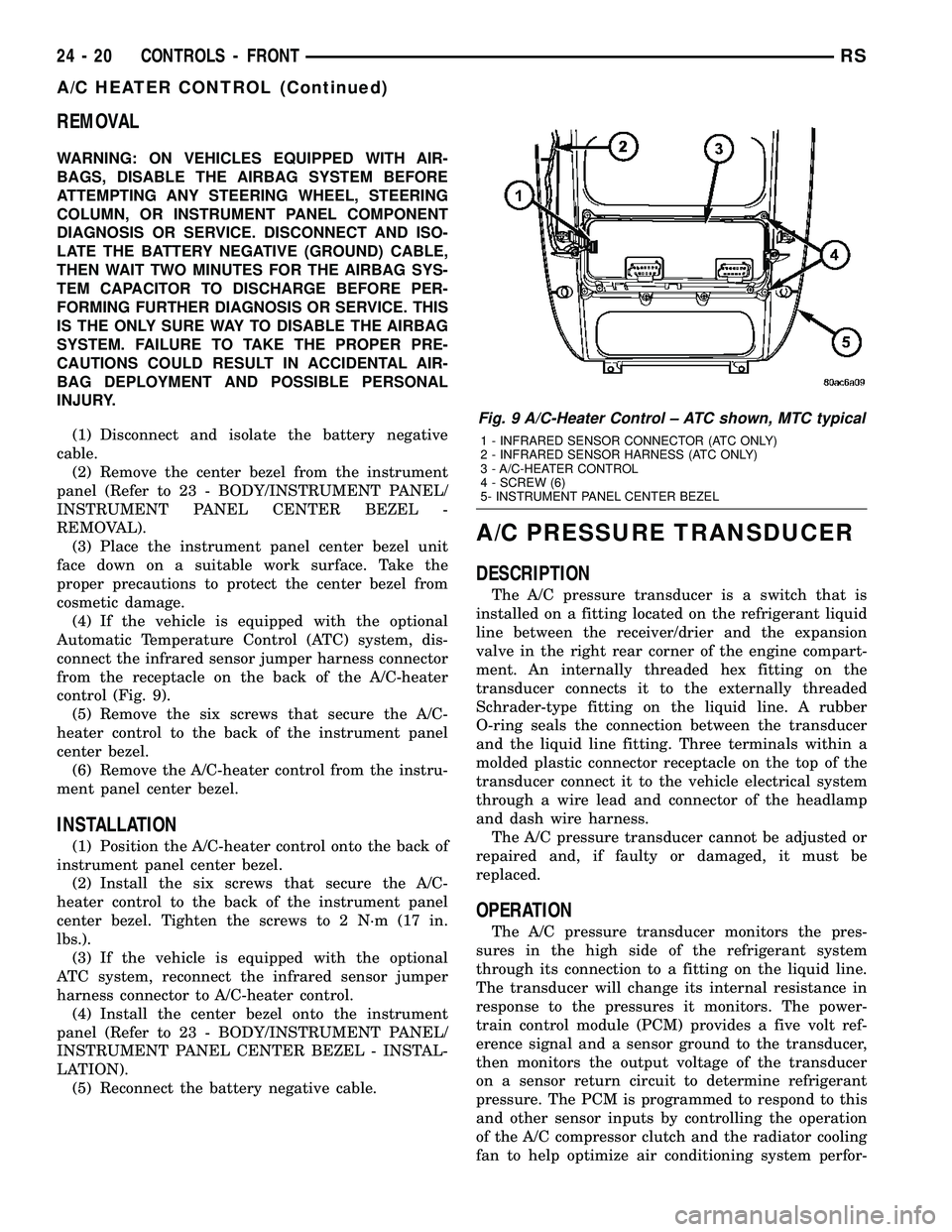
(4) If the vehicle is equipped with the optional
Automatic Temperature Control (ATC) system, dis-
connect the infrared sensor jumper harness connector
from the receptacle on the back of the A/C-heater
control (Fig. 9).
(5) Remove the six screws that secure the A/C-
heater control to the back of the instrument panel
center bezel.
(6) Remove the A/C-heater control from the instru-
ment panel center bezel.
INSTALLATION
(1) Position the A/C-heater control onto the back of
instrument panel center bezel.
(2) Install the six screws that secure the A/C-
heater control to the back of the instrument panel
center bezel. Tighten the screws to 2 N´m (17 in.
lbs.).
(3) If the vehicle is equipped with the optional
ATC system, reconnect the infrared sensor jumper
harness connector to A/C-heater control.
(4) Install the center bezel onto the instrument
panel (Refer to 23 - BODY/INSTRUMENT PANEL/
INSTRUMENT PANEL CENTER BEZEL - INSTAL-
LATION).
(5) Reconnect the battery negative cable.
A/C PRESSURE TRANSDUCER
DESCRIPTION
The A/C pressure transducer is a switch that is
installed on a fitting located on the refrigerant liquid
line between the receiver/drier and the expansion
valve in the right rear corner of the engine compart-
ment. An internally threaded hex fitting on the
transducer connects it to the externally threaded
Schrader-type fitting on the liquid line. A rubber
O-ring seals the connection between the transducer
and the liquid line fitting. Three terminals within a
molded plastic connector receptacle on the top of the
transducer connect it to the vehicle electrical system
through a wire lead and connector of the headlamp
and dash wire harness.
The A/C pressure transducer cannot be adjusted or
repaired and, if faulty or damaged, it must be
replaced.
OPERATION
The A/C pressure transducer monitors the pres-
sures in the high side of the refrigerant system
through its connection to a fitting on the liquid line.
The transducer will change its internal resistance in
response to the pressures it monitors. The power-
train control module (PCM) provides a five volt ref-
erence signal and a sensor ground to the transducer,
then monitors the output voltage of the transducer
on a sensor return circuit to determine refrigerant
pressure. The PCM is programmed to respond to this
and other sensor inputs by controlling the operation
of the A/C compressor clutch and the radiator cooling
fan to help optimize air conditioning system perfor-
Fig. 9 A/C-Heater Control ± ATC shown, MTC typical
1 - INFRARED SENSOR CONNECTOR (ATC ONLY)
2 - INFRARED SENSOR HARNESS (ATC ONLY)
3 - A/C-HEATER CONTROL
4 - SCREW (6)
5- INSTRUMENT PANEL CENTER BEZEL
24 - 20 CONTROLS - FRONTRS
A/C HEATER CONTROL (Continued)