Page 1604 of 2339
(12) Install 2/4 Accumulator components as shown
in (Fig. 343).
(13) Torque 2/4 Accumulator retainer to 5 N´m (45
in. lbs.) (Fig. 344).
(14) Install Manual Shaft/Rooster Comb and
Transmission Range Sensor (Fig. 345).
(15) Make sure Manual Valve control pin is con-
tained within the rooster comb slot (Fig. 346). Install
Transmission Range Sensor retaining screw (Fig.
346) and torque to 5 N´m (45 in. lbs.).
Fig. 343 2/4 Accumulator Assembly
1 - VALVE BODY
2 - RETAINER PLATE
3 - DETENT SPRING
4 - RETURN SPRINGS
5 - PISTON
Fig. 344 2/4 Accumulator Retaining Plate
1 - 2±4 ACCUMULATOR RETAINING PLATE
2 - DETENT SPRING
Fig. 345 Install Manual Shaft/Rooster Comb and
Transmission Range Sensor
1 - TRANSMISSION RANGE SENSOR
2 - MANUAL SHAFT
3 - ROOSTER COMB
Fig. 346 Install Transmission Range Sensor
Retaining Screw
1 - TRANSMISSION RANGE SENSOR
2 - MANUAL VALVE CONTROL PIN
3 - RETAINING SCREW
RS40TE AUTOMATIC TRANSAXLE21 - 143
VALVE BODY (Continued)
Page 1606 of 2339
(3) Ensure the transaxle oil pan and transaxle
case sealing surfaces are clean and dry. Install an
1/8º bead of MopartSilicone Rubber Adhesive Seal-
ant to the oil pan and install (Fig. 351). Torque oil
pan-to-transaxle case bolts (Fig. 352) to 19 N´m (165
in. lbs.).
(4) Lower vehicle.(5) Connect transmission range sensor connector.
(6) Install manual valve lever to manual shaft.
(7) Install gearshift cable to manual valve lever.
(8) Connect battery negative cable.
(9) Fill transaxle with MopartATF +4 Transmis-
sion fluid. (Refer to 21 - TRANSMISSION/TRANS-
AXLE/AUTOMATIC - 41TE/FLUID - STANDARD
PROCEDURE)
Fig. 351 Oil Pan
1 - OIL PAN
2 - 1/8 INCH BEAD OF RTV SEALANT
3 - OIL FILTER
Fig. 352 Oil Pan Bolts
1 - OIL PAN BOLTS (USE RTV UNDER BOLT HEADS)
RS40TE AUTOMATIC TRANSAXLE21 - 145
VALVE BODY (Continued)
Page 1607 of 2339

41TE AUTOMATIC TRANSAXLE
TABLE OF CONTENTS
page page
41TE AUTOMATIC TRANSAXLE
DESCRIPTION........................147
OPERATION..........................149
DIAGNOSIS AND TESTING
DIAGNOSIS AND TESTING - 4XTE
TRANSAXLE GENERAL DIAGNOSIS......149
DIAGNOSIS AND TESTING - ROAD TEST . . 150
DIAGNOSIS AND TESTING - HYDRAULIC
PRESSURE TESTS...................150
DIAGNOSIS AND TESTING - CLUTCH AIR
PRESSURE TESTS...................153
DIAGNOSIS AND TESTING - TORQUE
CONVERTER HOUSING FLUID LEAKAGE . . 154
REMOVAL............................154
DISASSEMBLY........................157
ASSEMBLY...........................174
INSTALLATION........................196
SCHEMATICS AND DIAGRAMS
4XTE TRANSAXLE HYDRAULIC
SCHEMATICS.......................199
SPECIFICATIONS - 41TE TRANSAXLE......211
SPECIAL TOOLS
41TE AUTOMATIC TRANSAXLE.........213
ACCUMULATOR
DESCRIPTION........................218
OPERATION..........................218
DRIVING CLUTCHES
DESCRIPTION........................219
OPERATION..........................219
FINAL DRIVE
DESCRIPTION........................219
OPERATION..........................220
DISASSEMBLY........................220
ASSEMBLY...........................224
ADJUSTMENTS
ADJUSTMENT - DIFFERENTIAL BEARING
PRELOAD..........................228
FLUID
STANDARD PROCEDURE
FLUID LEVEL AND CONDITION CHECK . . . 230
STANDARD PROCEDURE - FLUID AND
FILTER SERVICE.....................231
GEAR SHIFT CABLE
REMOVAL............................233
INSTALLATION........................234
ADJUSTMENTS
GEARSHIFT CABLE ADJUSTMENT.......235
HOLDING CLUTCHES
DESCRIPTION........................236
OPERATION..........................236INPUT CLUTCH ASSEMBLY
DISASSEMBLY........................237
ASSEMBLY...........................246
OIL PUMP
DESCRIPTION........................261
OPERATION..........................261
DISASSEMBLY........................261
ASSEMBLY...........................263
PLANETARY GEARTRAIN
DESCRIPTION........................263
OPERATION..........................263
SEAL - OIL PUMP
REMOVAL............................264
INSTALLATION........................264
SHIFT INTERLOCK SOLENOID
DESCRIPTION........................264
OPERATION..........................265
DIAGNOSIS AND TESTING - BRAKE/
TRANSMISSION SHIFT INTERLOCK
SOLENOID..........................266
REMOVAL............................266
INSTALLATION........................267
SOLENOID/PRESSURE SWITCH ASSY
DESCRIPTION........................268
OPERATION..........................268
REMOVAL............................269
INSTALLATION........................270
SPEED SENSOR - INPUT
DESCRIPTION........................271
OPERATION..........................271
REMOVAL............................272
INSTALLATION........................272
SPEED SENSOR - OUTPUT
DESCRIPTION........................273
OPERATION..........................273
REMOVAL............................274
INSTALLATION........................274
TORQUE CONVERTER
DESCRIPTION........................275
OPERATION..........................278
REMOVAL............................280
INSTALLATION........................280
TRANSMISSION CONTROL RELAY
DESCRIPTION........................281
OPERATION..........................281
TRANSMISSION RANGE SENSOR
DESCRIPTION........................281
OPERATION..........................282
REMOVAL............................282
INSTALLATION........................282
21 - 146 41TE AUTOMATIC TRANSAXLERS
Page 1608 of 2339

VALVE BODY
DESCRIPTION........................283
OPERATION..........................283
REMOVAL............................284DISASSEMBLY........................286
ASSEMBLY...........................291
INSTALLATION........................295
41TE AUTOMATIC
TRANSAXLE
DESCRIPTION
The 41TE (Fig. 1) is a four-speed transaxle that is
a conventional hydraulic/mechanical assembly with
an integral differential, and is controlled with adap-
tive electronic controls and monitors. The hydraulic
system of the transaxle consists of the transaxle
fluid, fluid passages, hydraulic valves, and various
line pressure control components. An input clutch
assembly which houses the underdrive, overdrive,
and reverse clutches is used. It also utilizes separate
holding clutches: 2nd/4th gear and Low/Reverse. The
primary mechanical components of the transaxle con-
sist of the following:
²Three multiple disc input clutches
²Two multiple disc holding clutches
²Four hydraulic accumulators
²Two planetary gear sets
²Hydraulic oil pump
²Valve body²Solenoid/Pressure switch assembly
²Integral differential assembly
Control of the transaxle is accomplished by fully
adaptive electronics. Optimum shift scheduling is
accomplished through continuous real-time sensor
feedback information provided to the Powertrain
Control Module (PCM) or Transmission Control Mod-
ule (TCM).
The PCM/TCM is the heart of the electronic control
system and relies on information from various direct
and indirect inputs (sensors, switches, etc.) to deter-
mine driver demand and vehicle operating condi-
tions. With this information, the PCM/TCM can
calculate and perform timely and quality shifts
through various output or control devices (solenoid
pack, transmission control relay, etc.).
The PCM/TCM also performs certain self-diagnos-
tic functions and provides comprehensive information
(sensor data, DTC's, etc.) which is helpful in proper
diagnosis and repair. This information can be viewed
with the DRB scan tool.
RS41TE AUTOMATIC TRANSAXLE21 - 147
Page 1609 of 2339
Fig. 1 41TE Automatic Transaxle
1 - TRANSAXLE CASE 7 - REVERSE CLUTCH 13 - OUTPUT SHAFT GEAR
2 - TORQUE CONVERTER 8 - FRONT PLANET CARRIER 14 - TRANSFER SHAFT GEAR
3 - OIL PUMP 9 - 2/4 CLUTCH 15 - TRANSFER SHAFT
4 - INPUT SPEED SENSOR 10 - L/R CLUTCH 16 - DIFFERENTIAL
5 - UNDERDRIVE CLUTCH 11 - OUTPUT SPEED SENSOR 17 - CONVERTER DRIVE PLATE
6 - OVERDRIVE CLUTCH 12 - REAR PLANET CARRIER/OUTPUT
SHAFT18 - INPUT SHAFT
21 - 148 41TE AUTOMATIC TRANSAXLERS
41TE AUTOMATIC TRANSAXLE (Continued)
Page 1616 of 2339

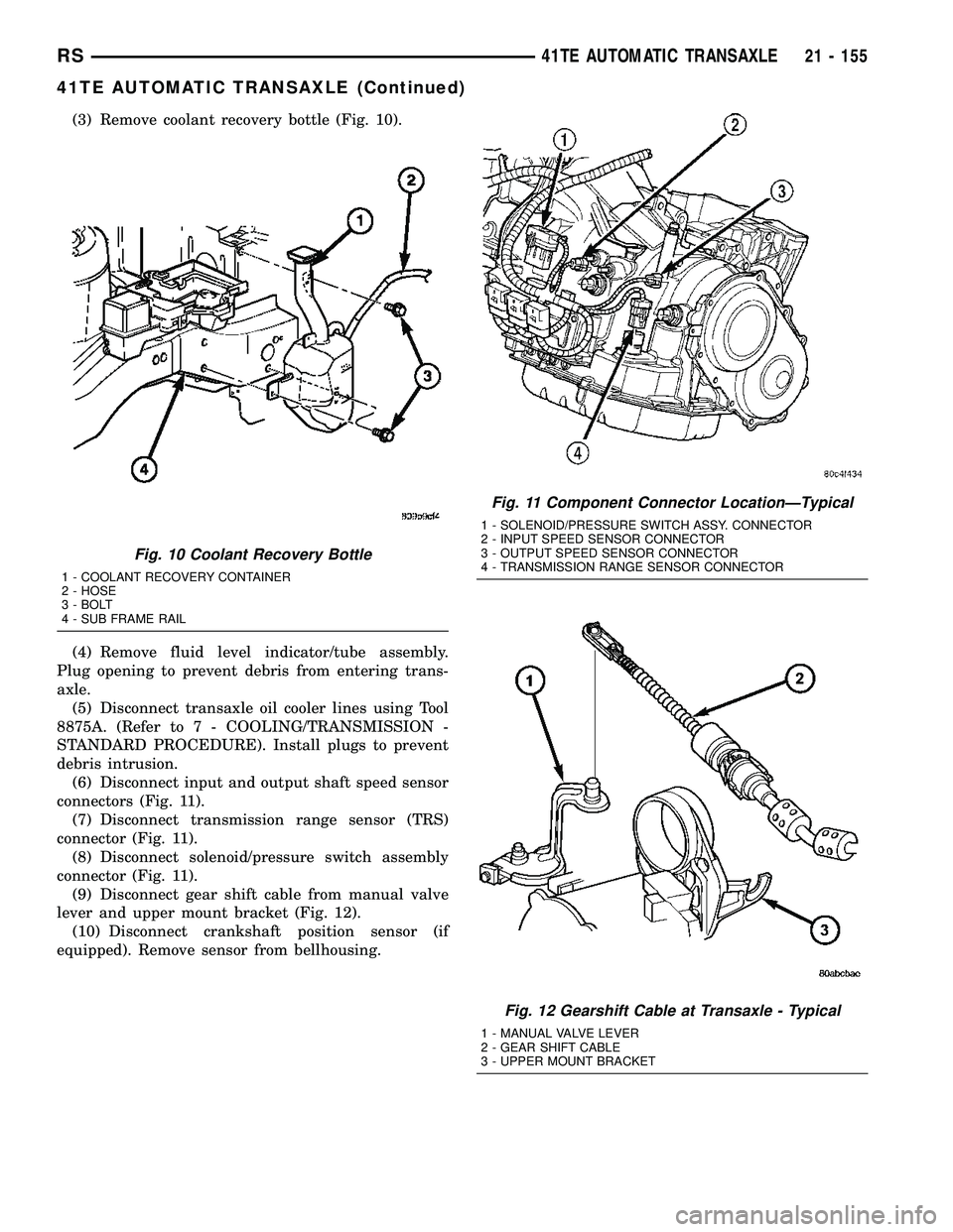
(3) Remove coolant recovery bottle (Fig. 10).
(4) Remove fluid level indicator/tube assembly.
Plug opening to prevent debris from entering trans-
axle.
(5) Disconnect transaxle oil cooler lines using Tool
8875A. (Refer to 7 - COOLING/TRANSMISSION -
STANDARD PROCEDURE). Install plugs to prevent
debris intrusion.
(6) Disconnect input and output shaft speed sensor
connectors (Fig. 11).
(7) Disconnect transmission range sensor (TRS)
connector (Fig. 11).
(8) Disconnect solenoid/pressure switch assembly
connector (Fig. 11).
(9) Disconnect gear shift cable from manual valve
lever and upper mount bracket (Fig. 12).
(10) Disconnect crankshaft position sensor (if
equipped). Remove sensor from bellhousing.
Fig. 10 Coolant Recovery Bottle
1 - COOLANT RECOVERY CONTAINER
2 - HOSE
3 - BOLT
4 - SUB FRAME RAIL
Fig. 11 Component Connector LocationÐTypical
1 - SOLENOID/PRESSURE SWITCH ASSY. CONNECTOR
2 - INPUT SPEED SENSOR CONNECTOR
3 - OUTPUT SPEED SENSOR CONNECTOR
4 - TRANSMISSION RANGE SENSOR CONNECTOR
Fig. 12 Gearshift Cable at Transaxle - Typical
1 - MANUAL VALVE LEVER
2 - GEAR SHIFT CABLE
3 - UPPER MOUNT BRACKET
RS41TE AUTOMATIC TRANSAXLE21 - 155
41TE AUTOMATIC TRANSAXLE (Continued)
Page 1618 of 2339

(28) Obtain helper and/or transmission jack.
Secure transmission jack to transaxle assembly.
(29) Remove upper mount bracket from transaxle
(Fig. 14).
(30) Remove remaining transaxle bellhousing-to-
engine bolts.
(31) Remove transaxle assembly from vehicle.
DISASSEMBLY
NOTE: If transaxle is being overhauled (clutch
and/or seal replacement) or replaced, it is neces-
sary to perform the PCM/TCM Quick Learn Proce-
dure. (Refer to 8 - ELECTRICAL/ELECTRONIC
CONTROL MODULES/POWERTRAIN/TRANSMIS-
SION CONTROL MODULE - STANDARD PROCE-
DURE)
NOTE: This procedure does not include final drive
(differential) disassembly.
(1) Remove input and output speed sensors.
(2) Remove three (3) solenoid/pressure switch
assembly-to-case bolts.
(3) Remove solenoid/pressure switch assembly and
gasket (Fig. 15).(4) Remove oil pan-to-case bolts (Fig. 16).
(5) Remove oil pan (Fig. 17).
Fig. 15 Solenoid/Pressure Switch Assembly and
Gasket
1 - SOLENOID/PRESSURE SWITCH ASSEMBLY
2 - GASKET
Fig. 16 Remove Oil Pan Bolts
1 - OIL PAN BOLTS (USE RTV UNDER BOLT HEADS)
Fig. 17 Remove Oil Pan
1 - OIL PAN
2 - 1/8 INCH BEAD OF MOPARTATF RTV (MS-GF41)
3 - OIL FILTER
RS41TE AUTOMATIC TRANSAXLE21 - 157
41TE AUTOMATIC TRANSAXLE (Continued)
Page 1621 of 2339
(14) Measure input shaft end play. Place transaxle
so input shaft is vertical. Set up end play set and
dial indicator as shown in (Fig. 27).Input shaft end
play should be within 0.13-0.64 mm (0.005-0.025
in.)If outside of this range, a #4 thrust plate change
is required. Record indicator reading for reference
upon reassembly.(15) Remove oil pump-to-case bolts (Fig. 28).
CAUTION: Be sure input speed sensor is removed
before removing oil pump.
(16) Install pullers Tool C-3752 as shown in (Fig.
29).
Fig. 26 Low/Reverse Accumulator
1 - PISTON
2 - RETURN SPRINGS
Fig. 27 Measure Input Shaft End Play Using End
Play Set 8266
1 - TOOL 8266±8
2 - TOOL 8266±2
3 - TOOL C-3339
Fig. 28 Remove Pump Attaching Bolts
1 - PUMP ATTACHING BOLTS
2 - PUMP HOUSING
Fig. 29 Install Tool C-3752
1 - PULLERS TOOL C-3752
2 - PUMP
21 - 160 41TE AUTOMATIC TRANSAXLERS
41TE AUTOMATIC TRANSAXLE (Continued)