2005 CHRYSLER CARAVAN location
[x] Cancel search: locationPage 1825 of 2339
INSTALLATION
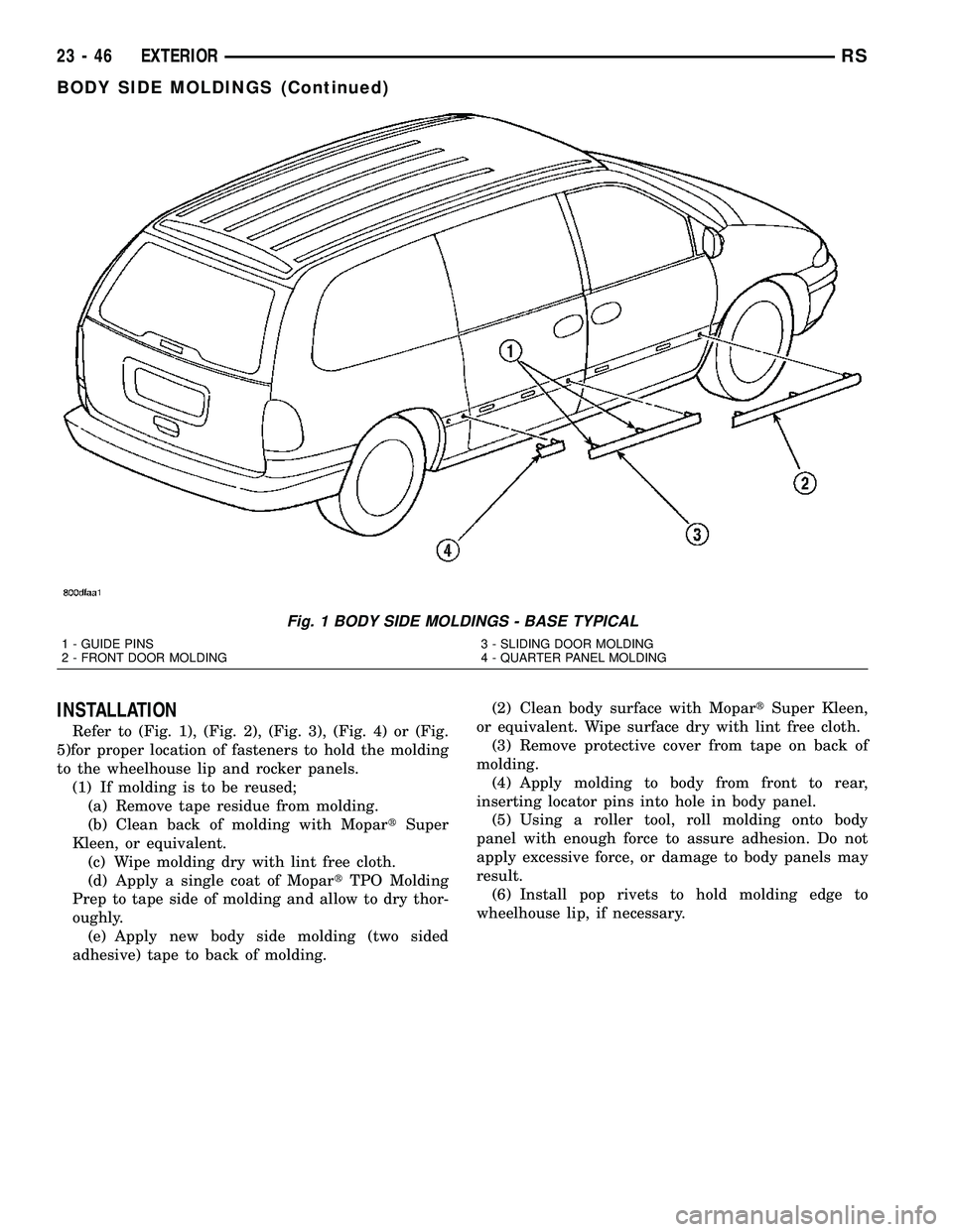
Refer to (Fig. 1), (Fig. 2), (Fig. 3), (Fig. 4) or (Fig.
5)for proper location of fasteners to hold the molding
to the wheelhouse lip and rocker panels.
(1) If molding is to be reused;
(a) Remove tape residue from molding.
(b) Clean back of molding with MopartSuper
Kleen, or equivalent.
(c) Wipe molding dry with lint free cloth.
(d) Apply a single coat of MopartTPO Molding
Prep to tape side of molding and allow to dry thor-
oughly.
(e) Apply new body side molding (two sided
adhesive) tape to back of molding.(2) Clean body surface with MopartSuper Kleen,
or equivalent. Wipe surface dry with lint free cloth.
(3) Remove protective cover from tape on back of
molding.
(4) Apply molding to body from front to rear,
inserting locator pins into hole in body panel.
(5) Using a roller tool, roll molding onto body
panel with enough force to assure adhesion. Do not
apply excessive force, or damage to body panels may
result.
(6) Install pop rivets to hold molding edge to
wheelhouse lip, if necessary.
Fig. 1 BODY SIDE MOLDINGS - BASE TYPICAL
1 - GUIDE PINS
2 - FRONT DOOR MOLDING3 - SLIDING DOOR MOLDING
4 - QUARTER PANEL MOLDING
23 - 46 EXTERIORRS
BODY SIDE MOLDINGS (Continued)
Page 1841 of 2339
HOOD
TABLE OF CONTENTS
page page
HINGE
REMOVAL.............................62
INSTALLATION.........................62
HOOD
REMOVAL.............................62
INSTALLATION.........................63
LATCH
REMOVAL.............................63INSTALLATION.........................63
LATCH RELEASE CABLE
REMOVAL.............................63
INSTALLATION.........................64
LATCH STRIKER
REMOVAL.............................64
INSTALLATION.........................64
HINGE
REMOVAL
(1) Remove Front Wiper Unit (Refer to 8 - ELEC-
TRICAL/WIPERS/WASHERS/WIPER MODULE -
REMOVAL) for procedure.
(2) Raise hood.
(3) Mark all bolt and hinge attachment locations
with a grease pencil or other suitable device to pro-
vide reference marks for installation.
(4) Remove pivot bolt from the body half of hood
hinge and use suitable device to support the hood.
(5) Remove bolts attaching body half of hood hinge
to front fender flange and remove hinge from vehicle
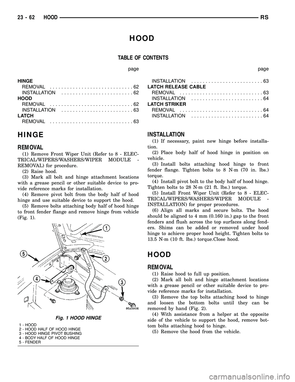
(Fig. 1).
INSTALLATION
(1) If necessary, paint new hinge before installa-
tion.
(2) Place body half of hood hinge in position on
vehicle.
(3) Install bolts attaching hood hinge to front
fender flange. Tighten bolts to 8 N´m (70 in. lbs.)
torque.
(4) Install pivot bolt to the body half of hood hinge.
Tighten bolts to 28 N´m (21 ft. lbs.) torque.
(5) Install Front Wiper Unit (Refer to 8 - ELEC-
TRICAL/WIPERS/WASHERS/WIPER MODULE -
INSTALLATION) for proper procedures.
(6) Align all marks and secure bolts. The hood
should be aligned to 4 mm (0.160 in.) gap to the front
fenders and flush across the top surfaces along fend-
ers. Shims can be added or removed under hood
hinge to achieve proper hood height. Tighten bolts to
13.5 N´m (10 ft. lbs.) torque.Close hood.
HOOD
REMOVAL
(1) Raise hood to full up position.
(2) Mark all bolt and hinge attachment locations
with a grease pencil or other suitable device to pro-
vide reference marks for installation.
(3) Remove the top bolts attaching hood to hinge
and loosen the bottom bolts until they can be
removed by hand (Fig. 2).
(4) With assistance from a helper at the opposite
side of the vehicle to support the hood, remove bot-
tom bolts attaching hood to hinge.
(5) Remove the hood from the vehicle.
Fig. 1 HOOD HINGE
1 - HOOD
2 - HOOD HALF OF HOOD HINGE
3 - HOOD HINGE PIVOT BUSHING
4 - BODY HALF OF HOOD HINGE
5 - FENDER
23 - 62 HOODRS
Page 1860 of 2339
CARPETS AND FLOOR MATS
REMOVAL
(1) Remove front seats. (Refer to 23 - BODY/
SEATS/SEAT - REMOVAL)
(2) Remove front center console.
(3) Remove heel blocker (plastic block below accel-
erator pedal).
(4) Remove the remaining seats. Refer to the Own-
er's Manual for the proper procedures.
(5) Remove front cowl panels and sill plates.
(6) Remove sliding door sill plates. (Refer to 23 -
BODY/INTERIOR/SLIDING DOOR SILL PLATE -
REMOVAL)
(7) Remove the cargo organizer, if equipped.
(8) Remove liftgate scuff plate. (Refer to 23 -
BODY/INTERIOR/LIFTGATE SCUFF PLATE -
REMOVAL)
(9) Remove lower B-pillar trim covers.
(10) Remove D-pillar trim covers.
(11) Remove Quarter trim panels.
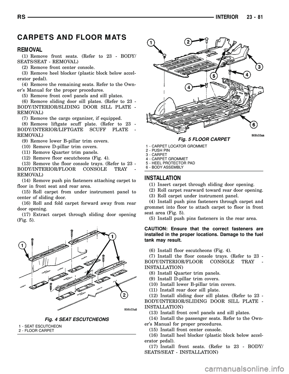
(12) Remove floor escutcheons (Fig. 4).
(13) Remove the floor console trays. (Refer to 23 -
BODY/INTERIOR/FLOOR CONSOLE TRAY -
REMOVAL)
(14) Remove push pin fasteners attaching carpet to
floor in front seat and rear area.
(15) Roll carpet from under instrument panel to
center of sliding door.
(16) Roll and fold carpet forward away from rear
door opening.
(17) Extract carpet through sliding door opening
(Fig. 5).
INSTALLATION
(1) Insert carpet through sliding door opening.
(2) Roll carpet rearward toward rear door opening.
(3) Roll carpet under instrument panel.
(4) Install push pins fasteners through carpet and
grommet into floor to attach carpet to floor in front
seat area (Fig. 5).
(5) Install push pins fasteners in the rear area.
CAUTION: Ensure that the correct fasteners are
installed in the proper locations. Damage to the fuel
tank may result.
(6) Install floor escutcheons (Fig. 4).
(7) Install the floor console trays. (Refer to 23 -
BODY/INTERIOR/FLOOR CONSOLE TRAY -
INSTALLATION)
(8) Install Quarter trim panels.
(9) Install D-pillar trim covers.
(10) Install lower B-pillar trim covers.
(11) Install rear door sill plate.
(12) Install sliding door sill plates. (Refer to 23 -
BODY/INTERIOR/SLIDING DOOR SILL PLATE -
INSTALLATION)
(13) Install front cowl panels and sill plates.
(14) Install the passenger seats. Refer to the Own-
er's Manual for proper procedures.
(15) Install front center console.
(16) Install heel blocker (plastic block below accel-
erator pedal).
(17) Install front seats. (Refer to 23 - BODY/
SEATS/SEAT - INSTALLATION)
Fig. 4 SEAT ESCUTCHEONS
1 - SEAT ESCUTCHEON
2 - FLOOR CARPET
Fig. 5 FLOOR CARPET
1 - CARPET LOCATOR GROMMET
2 - PUSH PIN
3 - CARPET
4 - CARPET GROMMET
5 - HEEL PROTECTOR PAD
6 - BODY ASSEMBLY
RSINTERIOR23-81
Page 1942 of 2339
(16) Apply 150 mm (6 in.) lengths of 50 mm (2 in.)
masking tape spaced 250 mm (10 in.) apart to hold
molding in place until urethane cures.
(17) Install A-pillar trim panels.
(18) Install cowl cover and wipers.
(19) Install inside rear view mirror.
(20) After urethane has cured, remove tape strips
and water test windshield to verify repair.SLIDING DOOR GLASS
REMOVAL
The temperature of the vehicle should be at least
21É C (70É F) before removing the stationary quarter/
sliding door glass. Butyl sealer becomes more pliable
at high temperatures.
(1) Remove interior trim as necessary to gain
access attaching locations on back of glass.
(2) Remove nuts holding stationary glass to fence.
(3)
Using razor knife, cut butyl sealer holding glass
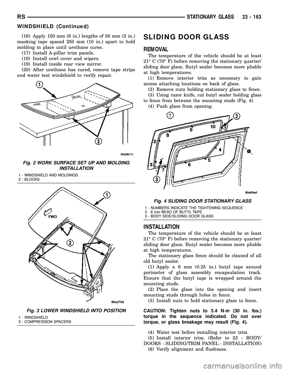
to fence from between the mounting studs (Fig. 4).
(4) Push glass from opening.
INSTALLATION
The temperature of the vehicle should be at least
21É C (70É F) before removing the stationary quarter/
sliding door glass. Butyl sealer becomes more pliable
at high temperatures.
The stationary glass fence should be cleaned of all
old butyl sealer.
(1) Applya6mm(0.25 in.) butyl tape around
perimeter of glass assembly encapsulation track.
Ensure that the butyl tape is wrapped around the
mounting studs.
(2) Place the glass into the opening and insert
mounting studs through holes in fence.
(3) Install nuts to hold stationary glass to fence.
CAUTION: Tighten nuts to 3.4 N´m (30 in. lbs.)
torque in the sequence indicated. Do not over
torque, or glass breakage may result (Fig. 4).
(4) Water test before installing interior trim.
(5) Install interior trim. (Refer to 23 - BODY/
DOORS - SLIDING/TRIM PANEL - INSTALLATION)
(6) Verify alignment and flushness.
Fig. 2 WORK SURFACE SET UP AND MOLDING
INSTALLATION
1 - WINDSHIELD AND MOLDINGS
2 - BLOCKS
Fig. 3 LOWER WINDSHIELD INTO POSITION
1 - WINDSHIELD
2 - COMPRESSION SPACERS
Fig. 4 SLIDING DOOR STATIONARY GLASS
1 - NUMBERS INDICATE THE TIGHTENING SEQUENCE
2-6mmBEAD OF BUTYL TAPE
3 - BODY SIDE/SLIDING DOOR GLASS
RSSTATIONARY GLASS23 - 163
WINDSHIELD (Continued)
Page 1943 of 2339
QUARTER WINDOW
REMOVAL
(1) Remove C-pillar trim.
(2) Open quarter glass to vent position.
(3) Disengage quarter window retainer from vent
motor arm.
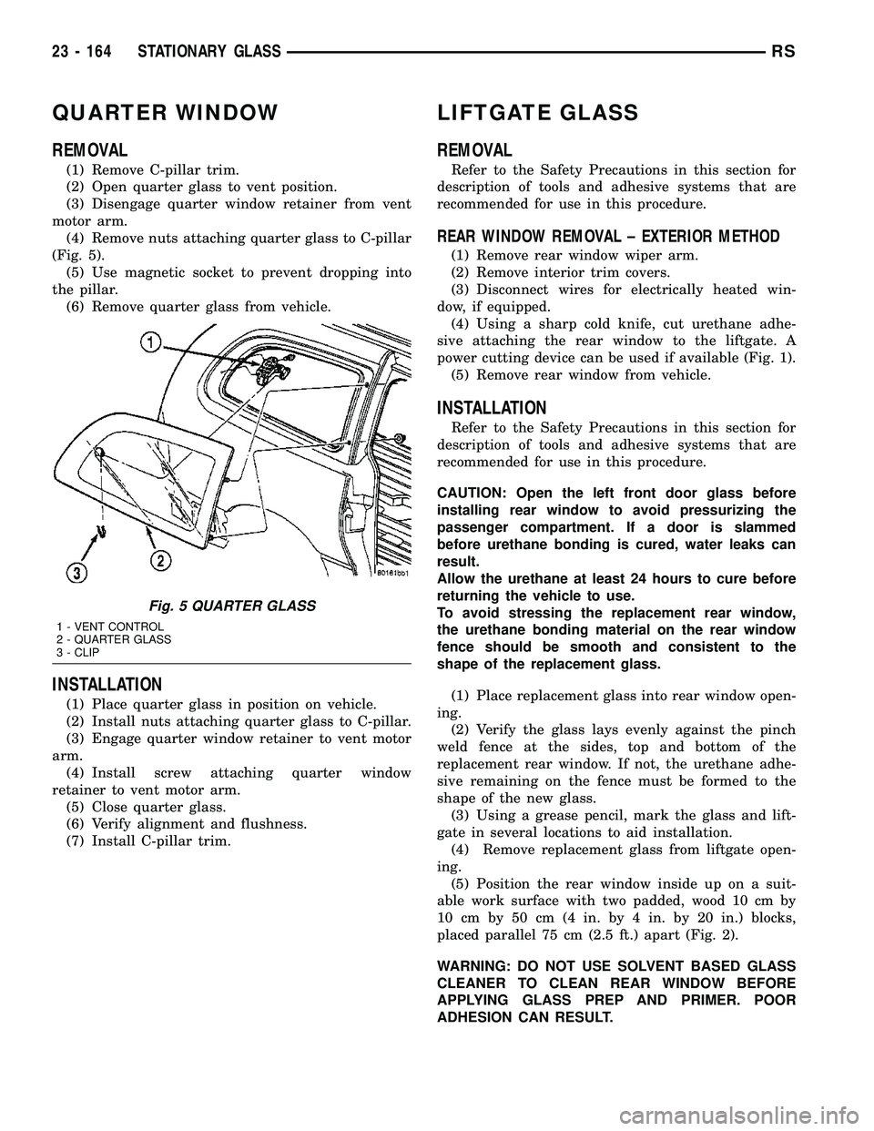
(4) Remove nuts attaching quarter glass to C-pillar
(Fig. 5).
(5) Use magnetic socket to prevent dropping into
the pillar.
(6) Remove quarter glass from vehicle.
INSTALLATION
(1) Place quarter glass in position on vehicle.
(2) Install nuts attaching quarter glass to C-pillar.
(3) Engage quarter window retainer to vent motor
arm.
(4) Install screw attaching quarter window
retainer to vent motor arm.
(5) Close quarter glass.
(6) Verify alignment and flushness.
(7) Install C-pillar trim.
LIFTGATE GLASS
REMOVAL
Refer to the Safety Precautions in this section for
description of tools and adhesive systems that are
recommended for use in this procedure.
REAR WINDOW REMOVAL ± EXTERIOR METHOD
(1) Remove rear window wiper arm.
(2) Remove interior trim covers.
(3) Disconnect wires for electrically heated win-
dow, if equipped.
(4) Using a sharp cold knife, cut urethane adhe-
sive attaching the rear window to the liftgate. A
power cutting device can be used if available (Fig. 1).
(5) Remove rear window from vehicle.
INSTALLATION
Refer to the Safety Precautions in this section for
description of tools and adhesive systems that are
recommended for use in this procedure.
CAUTION: Open the left front door glass before
installing rear window to avoid pressurizing the
passenger compartment. If a door is slammed
before urethane bonding is cured, water leaks can
result.
Allow the urethane at least 24 hours to cure before
returning the vehicle to use.
To avoid stressing the replacement rear window,
the urethane bonding material on the rear window
fence should be smooth and consistent to the
shape of the replacement glass.
(1) Place replacement glass into rear window open-
ing.
(2) Verify the glass lays evenly against the pinch
weld fence at the sides, top and bottom of the
replacement rear window. If not, the urethane adhe-
sive remaining on the fence must be formed to the
shape of the new glass.
(3) Using a grease pencil, mark the glass and lift-
gate in several locations to aid installation.
(4) Remove replacement glass from liftgate open-
ing.
(5) Position the rear window inside up on a suit-
able work surface with two padded, wood 10 cm by
10 cm by 50 cm (4 in. by 4 in. by 20 in.) blocks,
placed parallel 75 cm (2.5 ft.) apart (Fig. 2).
WARNING: DO NOT USE SOLVENT BASED GLASS
CLEANER TO CLEAN REAR WINDOW BEFORE
APPLYING GLASS PREP AND PRIMER. POOR
ADHESION CAN RESULT.
Fig. 5 QUARTER GLASS
1 - VENT CONTROL
2 - QUARTER GLASS
3 - CLIP
23 - 164 STATIONARY GLASSRS
Page 1945 of 2339
WEATHERSTRIP/SEALS
TABLE OF CONTENTS
page page
FRONT DOOR GLASS RUN WEATHERSTRIP
REMOVAL............................166
INSTALLATION........................166
FRONT DOOR OUTER BELT MOLDING
REMOVAL............................167
INSTALLATION........................167
FRONT DOOR WEATHERSTRIP
REMOVAL............................168INSTALLATION........................168
SLIDING DOOR WEATHERSTRIP
REMOVAL............................168
INSTALLATION........................168
FRONT DOOR INNER BELT MOLDING
REMOVAL............................168
INSTALLATION........................168
FRONT DOOR GLASS RUN
WEATHERSTRIP
REMOVAL
(1) Remove door frame closeout moldings.
(2) Pull weatherstrip from glass run channel at
rear of door frame, working from the bottom to the
top.
(3) Disengage clip attaching weatherstrip to door
frame.
(4) Pull weatherstrip from lip along top of door
frame (Fig. 1).
(5) Remove door trim panel.
(6) Remove door speaker, if equipped.
(7) Remove watershed as necessary to gain access
to screw attaching front lower corner of glass run
weatherstrip to inner door panel.
(8) Remove screw attaching glass run weatherstrip
to inner door panel.
(9) Remove inner belt weatherstrip.
(10) Pull weatherstrip from front glass run chan-
nel.
(11) Remove glass run weatherstrip from vehicle.
INSTALLATION
(1) Position glass run weatherstrip on vehicle (Fig.
1).
(2) Insert A-pillar section of the glass run into door
through belt line and lower to bottom of door using
molded corners as a guide.
NOTE: Care must be taken not to damage the medal
bracket when installing through the belt opening.
(3) Locate the top corner portion of the B-pillar
glass run section onto the roll frame and slide it up
until the part bottoms out on the header portion of
the roll frame.
NOTE: Do not JAM the corner into place.
(4) Install the entire B-pillar glass run onto roll
frame.
(5) Working from the B-pillar forward install the
first eight to twelve inches of the header glass run
onto the roll frame.
NOTE: Use care not to push or pull the header sec-
tion and the molded corner out of location.
23 - 166 WEATHERSTRIP/SEALSRS
Page 1947 of 2339
FRONT DOOR WEATHERSTRIP
REMOVAL
(1) Open front door.
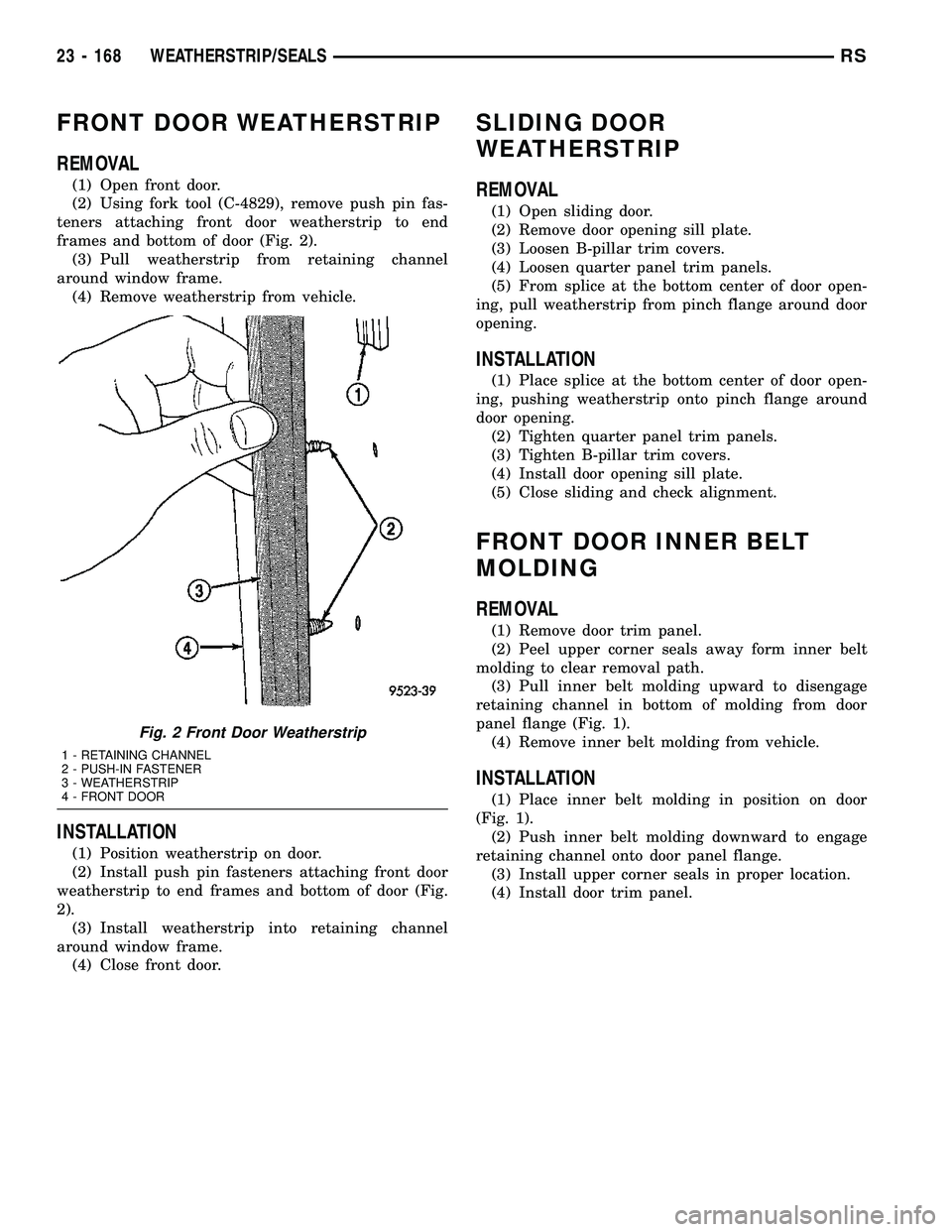
(2) Using fork tool (C-4829), remove push pin fas-
teners attaching front door weatherstrip to end
frames and bottom of door (Fig. 2).
(3) Pull weatherstrip from retaining channel
around window frame.
(4) Remove weatherstrip from vehicle.
INSTALLATION
(1) Position weatherstrip on door.
(2) Install push pin fasteners attaching front door
weatherstrip to end frames and bottom of door (Fig.
2).
(3) Install weatherstrip into retaining channel
around window frame.
(4) Close front door.
SLIDING DOOR
WEATHERSTRIP
REMOVAL
(1) Open sliding door.
(2) Remove door opening sill plate.
(3) Loosen B-pillar trim covers.
(4) Loosen quarter panel trim panels.
(5) From splice at the bottom center of door open-
ing, pull weatherstrip from pinch flange around door
opening.
INSTALLATION
(1) Place splice at the bottom center of door open-
ing, pushing weatherstrip onto pinch flange around
door opening.
(2) Tighten quarter panel trim panels.
(3) Tighten B-pillar trim covers.
(4) Install door opening sill plate.
(5) Close sliding and check alignment.
FRONT DOOR INNER BELT
MOLDING
REMOVAL
(1) Remove door trim panel.
(2) Peel upper corner seals away form inner belt
molding to clear removal path.
(3) Pull inner belt molding upward to disengage
retaining channel in bottom of molding from door
panel flange (Fig. 1).
(4) Remove inner belt molding from vehicle.
INSTALLATION
(1) Place inner belt molding in position on door
(Fig. 1).
(2) Push inner belt molding downward to engage
retaining channel onto door panel flange.
(3) Install upper corner seals in proper location.
(4) Install door trim panel.
Fig. 2 Front Door Weatherstrip
1 - RETAINING CHANNEL
2 - PUSH-IN FASTENER
3 - WEATHERSTRIP
4 - FRONT DOOR
23 - 168 WEATHERSTRIP/SEALSRS
Page 1956 of 2339
BODY STRUCTURE
TABLE OF CONTENTS
page page
GAP AND FLUSH
SPECIFICATIONS - GAP AND FLUSH
MEASUREMENTS....................177
OPENING DIMENSIONS
SPECIFICATIONS - BODY OPENING
DIMENSIONS........................180
SEALER LOCATIONS
SPECIFICATIONS
SPECIFICATIONS - BODY SEALING
LOCATIONS.........................183
SPECIFICATIONS - BODY SEALING
LOCATIONS - FOLD-IN-FLOOR ONLY.....209STRUCTURAL ADHESIVE LOCATIONS
SPECIFICATIONS
SPECIFICATIONS - STRUCTURAL
ADHESIVE LOCATIONS................218
SPECIFICATIONS - STRUCTURAL
ADHESIVE LOCATIONS - FOLD-IN-FLOOR
ONLY..............................228
WELD LOCATIONS
SPECIFICATIONS
SPECIFICATIONS - WELD LOCATIONS....234
SPECIFICATIONS - WELD LOCATIONS -
FOLD-IN-FLOOR.....................350
GAP AND FLUSH
SPECIFICATIONS - GAP AND FLUSH
MEASUREMENTS
INDEX
DESCRIPTION FIGURE
GAP & FLUSH MEASUREMENTS 1
RSBODY STRUCTURE23 - 177