2005 CHRYSLER CARAVAN engine oil
[x] Cancel search: engine oilPage 2227 of 2339
REMOVAL
2.4L/3.3L/3.8L ENGINES
WARNING: REFER TO THE APPLICABLE WARN-
INGS AND CAUTIONS FOR THIS SYSTEM BEFORE
PERFORMING THE FOLLOWING OPERATION (Refer
to 24 - HEATING & AIR CONDITIONING/PLUMBING -
FRONT - WARNING - A/C PLUMBING) and (Refer to
24 - HEATING & AIR CONDITIONING/PLUMBING -
FRONT - CAUTION - A/C PLUMBING).
NOTE: Before removing the A/C condenser, note the
location of each of the radiator and condenser air
seals. These air seals are used to direct air through
the A/C condenser and radiator. The air seals must
be reinstalled in their proper locations in order for
the A/C and engine cooling systems to perform as
designed.
(1) Recover the refrigerant from the refrigerant
system (Refer to 24 - HEATING & AIR CONDITION-
ING/PLUMBING - FRONT/REFRIGERANT - STAN-
DARD PROCEDURE - REFRIGERANT SYSTEM
RECOVERY).
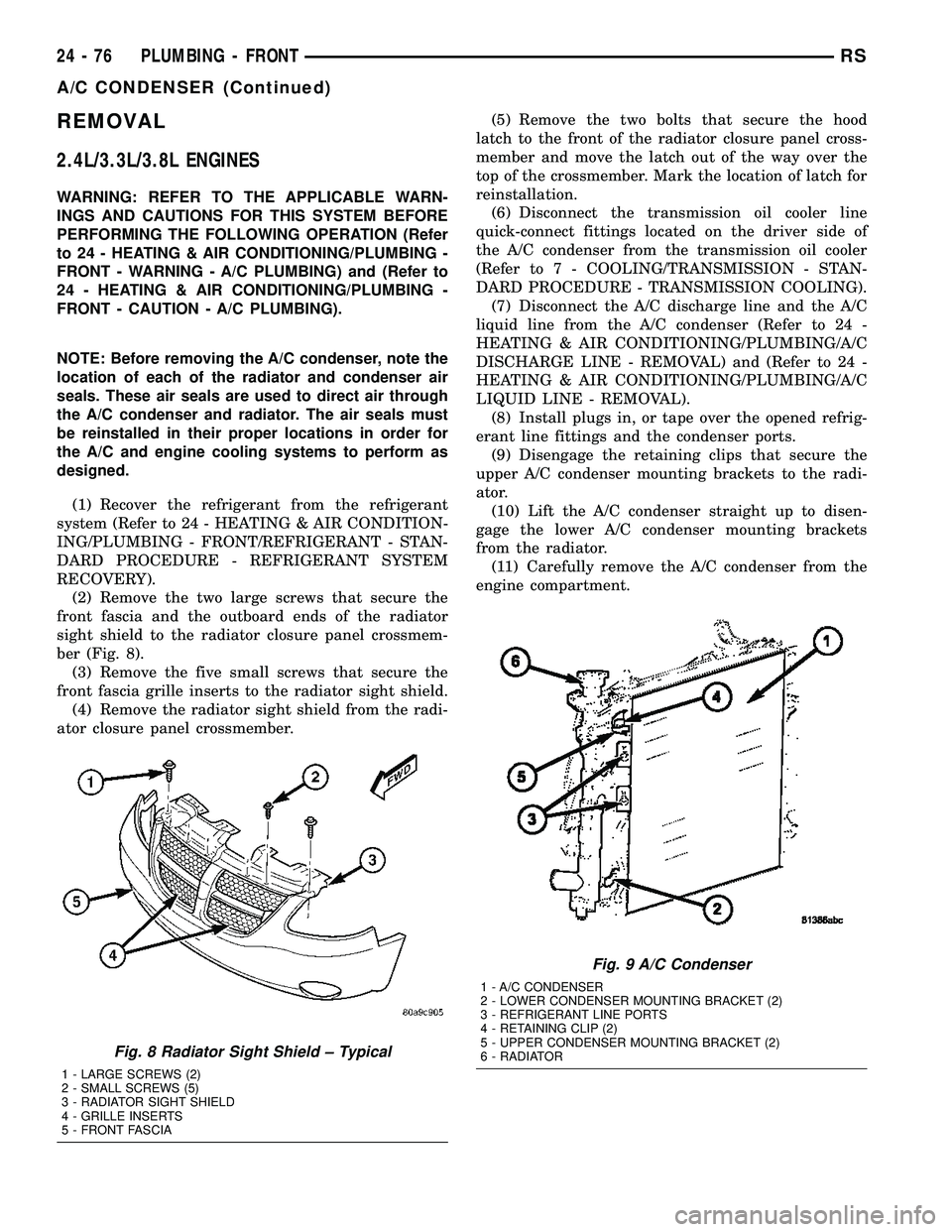
(2) Remove the two large screws that secure the
front fascia and the outboard ends of the radiator
sight shield to the radiator closure panel crossmem-
ber (Fig. 8).
(3) Remove the five small screws that secure the
front fascia grille inserts to the radiator sight shield.
(4) Remove the radiator sight shield from the radi-
ator closure panel crossmember.(5) Remove the two bolts that secure the hood
latch to the front of the radiator closure panel cross-
member and move the latch out of the way over the
top of the crossmember. Mark the location of latch for
reinstallation.
(6) Disconnect the transmission oil cooler line
quick-connect fittings located on the driver side of
the A/C condenser from the transmission oil cooler
(Refer to 7 - COOLING/TRANSMISSION - STAN-
DARD PROCEDURE - TRANSMISSION COOLING).
(7) Disconnect the A/C discharge line and the A/C
liquid line from the A/C condenser (Refer to 24 -
HEATING & AIR CONDITIONING/PLUMBING/A/C
DISCHARGE LINE - REMOVAL) and (Refer to 24 -
HEATING & AIR CONDITIONING/PLUMBING/A/C
LIQUID LINE - REMOVAL).
(8) Install plugs in, or tape over the opened refrig-
erant line fittings and the condenser ports.
(9) Disengage the retaining clips that secure the
upper A/C condenser mounting brackets to the radi-
ator.
(10) Lift the A/C condenser straight up to disen-
gage the lower A/C condenser mounting brackets
from the radiator.
(11) Carefully remove the A/C condenser from the
engine compartment.
Fig. 8 Radiator Sight Shield ± Typical
1 - LARGE SCREWS (2)
2 - SMALL SCREWS (5)
3 - RADIATOR SIGHT SHIELD
4 - GRILLE INSERTS
5 - FRONT FASCIA
Fig. 9 A/C Condenser
1 - A/C CONDENSER
2 - LOWER CONDENSER MOUNTING BRACKET (2)
3 - REFRIGERANT LINE PORTS
4 - RETAINING CLIP (2)
5 - UPPER CONDENSER MOUNTING BRACKET (2)
6 - RADIATOR
24 - 76 PLUMBING - FRONTRS
A/C CONDENSER (Continued)
Page 2228 of 2339
2.5L/2.8L DIESEL ENGINES
WARNING: REFER TO THE APPLICABLE WARN-
INGS AND CAUTIONS FOR THIS SYSTEM BEFORE
PERFORMING THE FOLLOWING OPERATION (Refer
to 24 - HEATING & AIR CONDITIONING/PLUMBING -
FRONT - WARNING - A/C PLUMBING) and (Refer to
24 - HEATING & AIR CONDITIONING/PLUMBING -
FRONT - CAUTION - A/C PLUMBING).
NOTE: Before removing the A/C condenser, note the
location of each of the radiator and condenser air
seals. These air seals are used to direct air through
the A/C condenser and radiator. The air seals must
be reinstalled in their proper locations in order for
the A/C and engine cooling systems to perform as
designed.
(1) Recover the refrigerant from the refrigerant
system (Refer to 24 - HEATING & AIR CONDITION-
ING/PLUMBING - FRONT/REFRIGERANT - STAN-
DARD PROCEDURE - REFRIGERANT SYSTEM
RECOVERY).
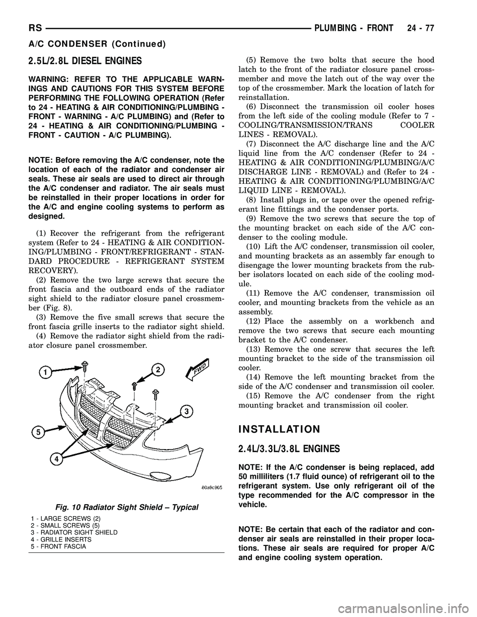
(2) Remove the two large screws that secure the
front fascia and the outboard ends of the radiator
sight shield to the radiator closure panel crossmem-
ber (Fig. 8).
(3) Remove the five small screws that secure the
front fascia grille inserts to the radiator sight shield.
(4) Remove the radiator sight shield from the radi-
ator closure panel crossmember.(5) Remove the two bolts that secure the hood
latch to the front of the radiator closure panel cross-
member and move the latch out of the way over the
top of the crossmember. Mark the location of latch for
reinstallation.
(6) Disconnect the transmission oil cooler hoses
from the left side of the cooling module (Refer to 7 -
COOLING/TRANSMISSION/TRANS COOLER
LINES - REMOVAL).
(7) Disconnect the A/C discharge line and the A/C
liquid line from the A/C condenser (Refer to 24 -
HEATING & AIR CONDITIONING/PLUMBING/A/C
DISCHARGE LINE - REMOVAL) and (Refer to 24 -
HEATING & AIR CONDITIONING/PLUMBING/A/C
LIQUID LINE - REMOVAL).
(8) Install plugs in, or tape over the opened refrig-
erant line fittings and the condenser ports.
(9) Remove the two screws that secure the top of
the mounting bracket on each side of the A/C con-
denser to the cooling module.
(10) Lift the A/C condenser, transmission oil cooler,
and mounting brackets as an assembly far enough to
disengage the lower mounting brackets from the rub-
ber isolators located on each side of the cooling mod-
ule.
(11) Remove the A/C condenser, transmission oil
cooler, and mounting brackets from the vehicle as an
assembly.
(12) Place the assembly on a workbench and
remove the two screws that secure each mounting
bracket to the A/C condenser.
(13) Remove the one screw that secures the left
mounting bracket to the side of the transmission oil
cooler.
(14) Remove the left mounting bracket from the
side of the A/C condenser and transmission oil cooler.
(15) Remove the A/C condenser from the right
mounting bracket and transmission oil cooler.
INSTALLATION
2.4L/3.3L/3.8L ENGINES
NOTE: If the A/C condenser is being replaced, add
50 milliliters (1.7 fluid ounce) of refrigerant oil to the
refrigerant system. Use only refrigerant oil of the
type recommended for the A/C compressor in the
vehicle.
NOTE: Be certain that each of the radiator and con-
denser air seals are reinstalled in their proper loca-
tions. These air seals are required for proper A/C
and engine cooling system operation.
Fig. 10 Radiator Sight Shield ± Typical
1 - LARGE SCREWS (2)
2 - SMALL SCREWS (5)
3 - RADIATOR SIGHT SHIELD
4 - GRILLE INSERTS
5 - FRONT FASCIA
RSPLUMBING - FRONT24-77
A/C CONDENSER (Continued)
Page 2229 of 2339

(1) Position the A/C condenser into the engine
compartment.
(2) Carefully lower the A/C condenser straight
down to engage the lower mounting brackets to the
radiator.
(3) Engage the upper A/C condenser mounting
brackets to the radiator. Be sure that the upper
retaining clips are fully engaged to the upper mount-
ing brackets.
(4) Remove the tape or plugs from the opened
refrigerant line fittings and the condenser ports.
(5) Connect the A/C discharge line and the A/C liq-
uid line to the A/C condenser (Refer to 24 - HEAT-
ING & AIR CONDITIONING/PLUMBING/A/C
DISCHARGE LINE - INSTALLATION) and (Refer to
24 - HEATING & AIR CONDITIONING/PLUMBING/
A/C LIQUID LINE - INSTALLATION).
(6) Connect the transmission oil cooler lines to the
A/C Condenser. Be sure that the quick-connect fit-
tings are fully engaged to the cooler tapping block
(Refer to 7 - COOLING/TRANSMISSION - STAN-
DARD PROCEDURE - TRANSMISSION COOLING).
(7) Position the hood latch onto the front of the
radiator closure panel crossmember.
(8) Install the two screws that secure the hood
latch to the crossmember. Check and adjust the hoodlatch as required. Tighten the bolts to 14 N´m (123
in. lbs.).
(9) Position the radiator sight shield onto the radi-
ator closure panel crossmember.
(10) Install the five small screws that secure the
front fascia grille inserts to the radiator sight shield.
Tighten the screws to 2 N´m (17 in. lbs.).
(11) Install the two large screws that secure the
front fascia and the outboard ends of the radiator
sight shield to the radiator closure panel crossmem-
ber. Tighten the screws to 6 N´m (53 in. lbs.).
(12) Evacuate the refrigerant system (Refer to 24 -
HEATING & AIR CONDITIONING/PLUMBING -
FRONT/REFRIGERANT - STANDARD PROCE-
DURE - REFRIGERANT SYSTEM EVACUATE).
(13) Charge the refrigerant system (Refer to 24 -
HEATING & AIR CONDITIONING/PLUMBING -
FRONT/REFRIGERANT - STANDARD PROCE-
DURE - REFRIGERANT SYSTEM CHARGE).
2.5L/2.8L DIESEL ENGINES
NOTE: If the A/C condenser is being replaced, add
50 milliliters (1.7 fluid ounce) of refrigerant oil to the
refrigerant system. Use only refrigerant oil of the
type recommended for the A/C compressor in the
vehicle.
NOTE: Be certain that each of the radiator and con-
denser air seals are reinstalled in their proper loca-
tions. These air seals are required for proper A/C
and engine cooling system operation.
(1) Position the A/C condenser onto the right
mounting bracket and transmission oil cooler unit.
(2) Position the left mounting bracket onto the side
of the A/C condenser and transmission oil cooler.
(3) Install the screw that secures the left mounting
bracket to the side of the transmission oil cooler.
Tighten the screw to 5 N´m (45 in. lbs.).
(4) Install the two screws that secure each mount-
ing bracket to the sides of the A/C condenser. Tighten
the screws to 5 N´m (45 in. lbs.).
NOTE: Verify that the A/C condenser isolators are
all installed and positioned correctly.
(5) Position the A/C condenser, transmission oil
cooler, and mounting brackets into the vehicle as an
assembly. Be certain that the lower mounting brack-
ets are engaged into the rubber isolators located on
each side of the cooling module.
(6) Install the two screws that secure the top of
the mounting bracket on each side of the A/C con-
denser to the cooling module. Tighten the screws to 5
N´m (45 in. lbs.).
Fig. 11 A/C Condenser ± 2.5L/2.8L Diesel Engines
1 - BOLT (2)
2 - LOWER MOUNT ISOLATOR (2)
3 - A/C CONDENSER
24 - 78 PLUMBING - FRONTRS
A/C CONDENSER (Continued)
Page 2230 of 2339
(7) Remove the tape or plugs from the opened
refrigerant line fittings and the condenser ports.
(8) Connect the A/C discharge line and the A/C liq-
uid line to the A/C condenser (Refer to 24 - HEAT-
ING & AIR CONDITIONING/PLUMBING/A/C
DISCHARGE LINE - INSTALLATION) and (Refer to
24 - HEATING & AIR CONDITIONING/PLUMBING/
A/C LIQUID LINE - INSTALLATION).
(9) Reconnect the hoses to the transmission oil
cooler fittings on the left side of the cooling module
(Refer to 7 - COOLING/TRANSMISSION/TRANS
COOLER LINES - INSTALLATION).
(10) Reposition the hood latch to the front of the
radiator closure panel crossmember.
(11) Install the two screws that secure the hood
latch to the front of the radiator closure panel cross-
member. Check and adjust the hood latch as needed.
Tighten the screws to 14 N´m (123 in. lbs.).
(12) Position the radiator sight shield onto the
radiator closure panel crossmember.
(13) Install the five small screws that secure the
front fascia grille inserts to the radiator sight shield.
Tighten the screws to 2 N´m (17 in. lbs.).
(14) Install the two large screws that secure the
front fascia and the outboard ends of the radiator
sight shield to the radiator closure panel crossmem-
ber. Tighten the screws to 6 N´m (53 in. lbs.).
(15) Evacuate the refrigerant system (Refer to 24 -
HEATING & AIR CONDITIONING/PLUMBING -
FRONT/REFRIGERANT - STANDARD PROCE-
DURE - REFRIGERANT SYSTEM EVACUATE).
(16) Charge the refrigerant system (Refer to 24 -
HEATING & AIR CONDITIONING/PLUMBING -
FRONT/REFRIGERANT - STANDARD PROCE-
DURE - REFRIGERANT SYSTEM CHARGE).
A/C DISCHARGE LINE
REMOVAL
WARNING: REFER TO THE APPLICABLE WARN-
INGS AND CAUTIONS FOR THIS SYSTEM BEFORE
PERFORMING THE FOLLOWING OPERATION (Refer
to 24 - HEATING & AIR CONDITIONING/PLUMBING -
FRONT - WARNING - A/C PLUMBING) and (Refer to
24 - HEATING & AIR CONDITIONING/PLUMBING -
FRONT - CAUTION - A/C PLUMBING).
(1) Recover the refrigerant from the refrigerant
system (Refer to 24 - HEATING & AIR CONDITION-
ING/PLUMBING - FRONT/REFRIGERANT - STAN-
DARD PROCEDURE - REFRIGERANT SYSTEM
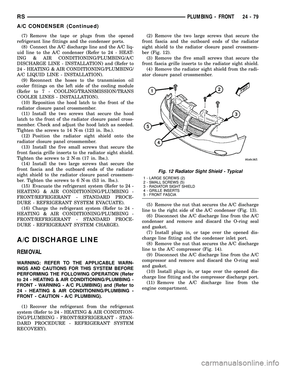
RECOVERY).(2) Remove the two large screws that secure the
front fascia and the outboard ends of the radiator
sight shield to the radiator closure panel crossmem-
ber (Fig. 12).
(3) Remove the five small screws that secure the
front fascia grille inserts to the radiator sight shield.
(4) Remove the radiator sight shield from the radi-
ator closure panel crossmember.
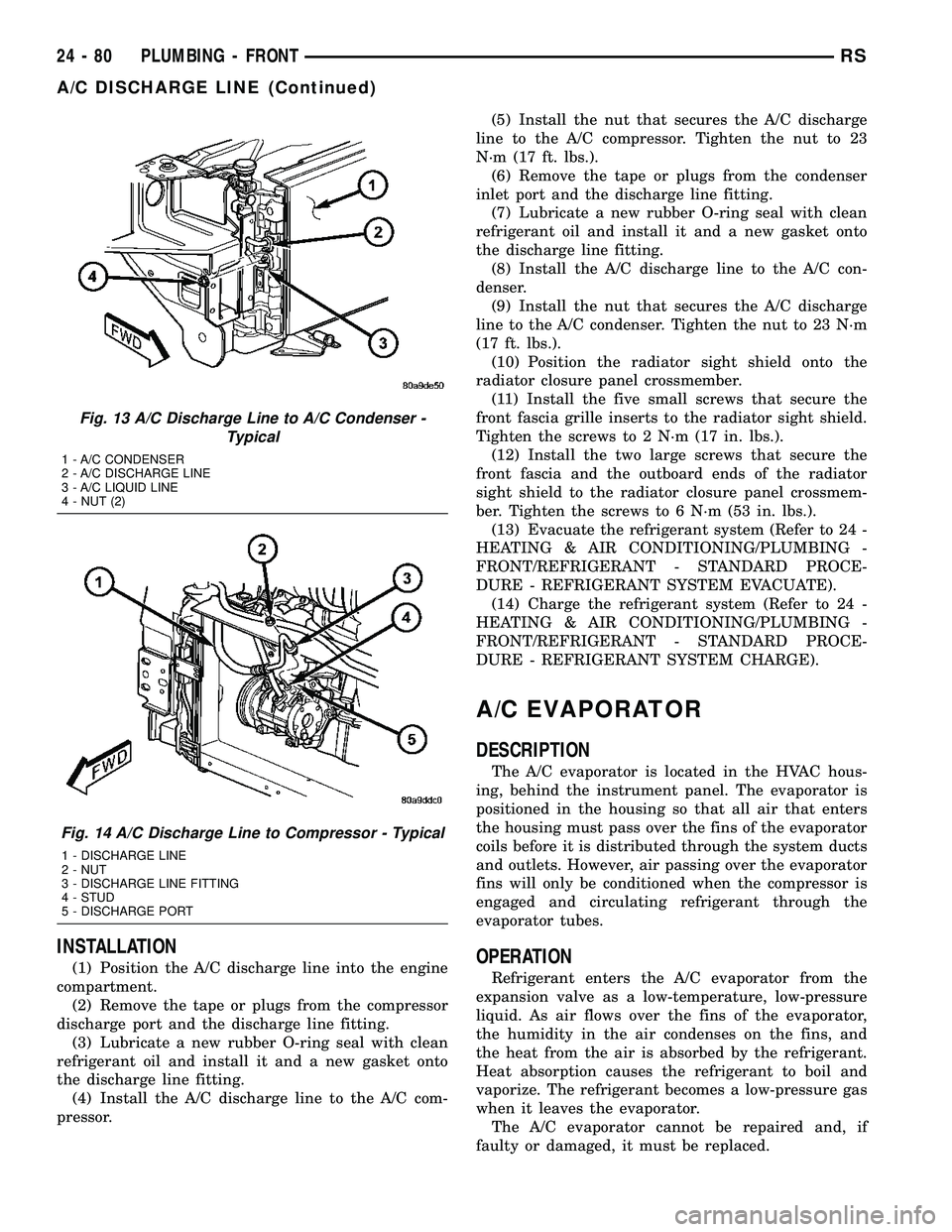
(5) Remove the nut that secures the A/C discharge
line to the right side of the A/C condenser (Fig. 13).
(6) Disconnect the A/C discharge line from the A/C
condenser and remove and discard the O-ring seal
and gasket.
(7) Install plugs in, or tape over the opened dis-
charge line fitting and the condenser inlet port.
(8) Remove the nut that secures the A/C discharge
line to the A/C compressor (Fig. 14).
(9) Disconnect the A/C discharge line from the A/C
compressor and remove and discard the O-ring seal
and gasket.
(10) Install plugs in, or tape over the opened dis-
charge line fitting and the compressor discharge port.
(11) Remove the A/C discharge line from the
engine compartment.
Fig. 12 Radiator Sight Shield - Typical
1 - LARGE SCREWS (2)
2 - SMALL SCREWS (5)
3 - RADIATOR SIGHT SHIELD
4 - GRILLE INSERTS
5 - FRONT FASCIA
RSPLUMBING - FRONT24-79
A/C CONDENSER (Continued)
Page 2231 of 2339
INSTALLATION
(1) Position the A/C discharge line into the engine
compartment.
(2) Remove the tape or plugs from the compressor
discharge port and the discharge line fitting.
(3) Lubricate a new rubber O-ring seal with clean
refrigerant oil and install it and a new gasket onto
the discharge line fitting.
(4) Install the A/C discharge line to the A/C com-
pressor.(5) Install the nut that secures the A/C discharge
line to the A/C compressor. Tighten the nut to 23
N´m (17 ft. lbs.).
(6) Remove the tape or plugs from the condenser
inlet port and the discharge line fitting.
(7) Lubricate a new rubber O-ring seal with clean
refrigerant oil and install it and a new gasket onto
the discharge line fitting.
(8) Install the A/C discharge line to the A/C con-
denser.
(9) Install the nut that secures the A/C discharge
line to the A/C condenser. Tighten the nut to 23 N´m
(17 ft. lbs.).
(10) Position the radiator sight shield onto the
radiator closure panel crossmember.
(11) Install the five small screws that secure the
front fascia grille inserts to the radiator sight shield.
Tighten the screws to 2 N´m (17 in. lbs.).
(12) Install the two large screws that secure the
front fascia and the outboard ends of the radiator
sight shield to the radiator closure panel crossmem-
ber. Tighten the screws to 6 N´m (53 in. lbs.).
(13) Evacuate the refrigerant system (Refer to 24 -
HEATING & AIR CONDITIONING/PLUMBING -
FRONT/REFRIGERANT - STANDARD PROCE-
DURE - REFRIGERANT SYSTEM EVACUATE).
(14) Charge the refrigerant system (Refer to 24 -
HEATING & AIR CONDITIONING/PLUMBING -
FRONT/REFRIGERANT - STANDARD PROCE-
DURE - REFRIGERANT SYSTEM CHARGE).
A/C EVAPORATOR
DESCRIPTION
The A/C evaporator is located in the HVAC hous-
ing, behind the instrument panel. The evaporator is
positioned in the housing so that all air that enters
the housing must pass over the fins of the evaporator
coils before it is distributed through the system ducts
and outlets. However, air passing over the evaporator
fins will only be conditioned when the compressor is
engaged and circulating refrigerant through the
evaporator tubes.
OPERATION
Refrigerant enters the A/C evaporator from the
expansion valve as a low-temperature, low-pressure
liquid. As air flows over the fins of the evaporator,
the humidity in the air condenses on the fins, and
the heat from the air is absorbed by the refrigerant.
Heat absorption causes the refrigerant to boil and
vaporize. The refrigerant becomes a low-pressure gas
when it leaves the evaporator.
The A/C evaporator cannot be repaired and, if
faulty or damaged, it must be replaced.
Fig. 13 A/C Discharge Line to A/C Condenser -
Typical
1 - A/C CONDENSER
2 - A/C DISCHARGE LINE
3 - A/C LIQUID LINE
4 - NUT (2)
Fig. 14 A/C Discharge Line to Compressor - Typical
1 - DISCHARGE LINE
2 - NUT
3 - DISCHARGE LINE FITTING
4 - STUD
5 - DISCHARGE PORT
24 - 80 PLUMBING - FRONTRS
A/C DISCHARGE LINE (Continued)
Page 2234 of 2339
(13) Install plugs in, or tape over the opened suc-
tion line and liquid line fittings and both expansion
valve ports.
(14) Remove the two screws that secure the A/C
expansion valve to the evaporator tube tapping plate.
(15) On RG models, disconnect the HVAC wire
harness connector from the evaporator temperature
sensor.
(16) Remove the A/C expansion valve from the
evaporator inlet and outlet tube fittings.
(17) Remove the seals from the evaporator inlet
and outlet tube fittings and discard.
(18) Install plugs in, or tape over the opened evap-
orator inlet and outlet tube fittings and both expan-
sion valve ports.
(19) On RG models, remove the evaporator tem-
perature sensor retainer and evaporator temperature
sensor from the A/C expansion valve, if required.
INSTALLATION
NOTE: Any grease removed with the evaporator
temperature sensor must be replaced. Failure to do
so could result in poor A/C performance.
(1) On RG models, install the evaporator tempera-
ture sensor and retainer onto the A/C expansion
valve, if removed.
(2) Remove the tape or plugs from the evaporator
inlet and outlet tube fittings and both ports on the
back of the A/C expansion valve.(3) Lubricate new rubber O-ring seals with clean
refrigerant oil and install them on the evaporator
inlet and outlet tube fittings.
(4) Position the A/C expansion valve onto the evap-
orator inlet and outlet tube fittings.
(5) Install the two screws that secure the A/C
expansion valve to the evaporator tube tapping plate
plate. Tighten the screws to 11 N´m (97 in. lbs.).
(6) On RG models, connect the HVAC wire harness
connector to the evaporator temperature sensor.
(7) Remove the tape or plugs from the front liquid
line rear section and suction line fittings for the
expansion valve and both ports on the front of the
expansion valve.
(8) Lubricate new rubber O-ring seals with clean
refrigerant oil and install them on the front liquid
line rear section and suction line fittings for the
expansion valve.
(9) Connect the liquid line and suction line fittings
to the expansion valve.
(10) Install the nut that secures the suction line
and liquid line fittings to the stud on the expansion
valve. Tighten the nut to 23 N´m (17 ft. lbs.).
(11) Remove the tape or plugs from the liquid line
rear section fitting and the receiver/drier outlet port.
(12) Lubricate a new rubber O-ring seal with clean
refrigerant oil and install it on the liquid line fitting.
(13) Connect the liquid line fitting to the receiver/
drier outlet port.
(14) Install the screw that secures the liquid line
fitting to the receiver/drier. Tighten the screw to 11
N´m (97 in. lbs.).
(15) Connect the wire harness connector to the A/C
pressure transducer.
(16) Connect the drain tube to the wiper module
drain on the right side of the engine compartment.
(17) Install the air cleaner housing.
(18) Reconnect the battery negative cable.
(19) Evacuate the refrigerant system (Refer to 24 -
HEATING & AIR CONDITIONING/PLUMBING -
FRONT/REFRIGERANT - STANDARD PROCE-
DURE - REFRIGERANT SYSTEM EVACUATE).
(20) Charge the refrigerant system (Refer to 24 -
HEATING & AIR CONDITIONING/PLUMBING -
FRONT/REFRIGERANT - STANDARD PROCE-
DURE - REFRIGERANT SYSTEM CHARGE).
HEATER CORE
DESCRIPTION
The heater core is located in the distribution hous-
ing, which is attached to the HVAC housing, behind
the instrument panel. It is a heat exchanger made of
rows of tubes and fins. One end of the core is fitted
with a molded plastic tank, which includes integral
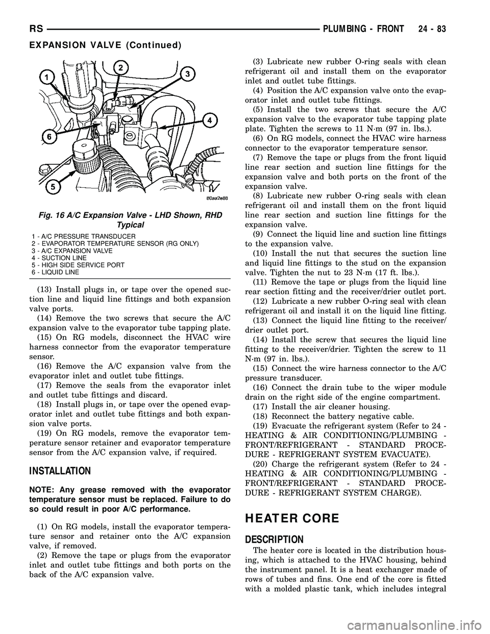
Fig. 16 A/C Expansion Valve - LHD Shown, RHD
Typical
1 - A/C PRESSURE TRANSDUCER
2 - EVAPORATOR TEMPERATURE SENSOR (RG ONLY)
3 - A/C EXPANSION VALVE
4 - SUCTION LINE
5 - HIGH SIDE SERVICE PORT
6 - LIQUID LINE
RSPLUMBING - FRONT24-83
EXPANSION VALVE (Continued)
Page 2237 of 2339
(3) Align the engine compartment ends of both
heater core tubes with the openings in the dash
panel seal and push them simultaneously forward
through the seal far enough to engage the heater
core ends of the tubes with the heater core supply
and return ports.
(4) Position both heater core tubes and the sealing
plate simultaneously to the heater core supply and
return ports.
NOTE: The heater core tubes each have a slot that
must be indexed to a location tab within each of the
heater core ports. Adjust the position of the tubes
as required so that the sealing plate fits flush
against the heater core supply and return ports,
which indicates that the tubes are properly indexed.
(5) Index both heater core tubes to the heater core
ports.
(6) Install the screw that secures the heater core
tube sealing plate to the heater core supply and
return ports. Tighten the screw to 3 N´m (27 in. lbs.).
(7) Install the silencer under the driver side end of
the instrument panel.
(8) Connect the heater hoses to the heater hose
tubes (Refer to 24 - HEATING & AIR CONDITION-
ING/PLUMBING/HEATER INLET HOSE - INSTAL-
LATION) and(Refer to 24 - HEATING & AIR
CONDITIONING/PLUMBING/HEATER RETURN
HOSE - INSTALLATION).
(9) Reconnect the battery negative cable.
(10) Refill the engine cooling system (Refer to 7 -
COOLING - STANDARD PROCEDURE - COOLING
SYSTEM REFILL).
FRONT HEATER CORE
(1) While pushing the brake pedal downward and
pulling the accelerator pedal upward far enough for
clearance, slide the heater core into the distribution
housing.
(2) Install the two screws that secure the heater
core mounting plate to the distribution housing.
Tighten the screws to 2 N´m (17 in. lbs.).(3) Install the heater core tubes (Refer to 24 -
HEATING & AIR CONDITIONING/PLUMBING/
HEATER CORE - INSTALLATION).
(4) Reconnect the power brake booster input rod
(push rod) to the pin on the brake pedal arm (Refer
to 5 - BRAKES/HYDRAULIC/MECHANICAL/
POWER BRAKE BOOSTER - INSTALLATION).
(5) Reinstall the brake lamp switch into its mount-
ing bracket (Refer to 8 - ELECTRICAL/LAMPS/
LIGHTING - EXTERIOR/BRAKE LAMP SWITCH -
INSTALLATION).
(6) Reinstall the silencer boot around the base of
the lower steering shaft on the dash panel.
(7) Reconnect the battery negative cable.
(8) Refill the engine cooling system (Refer to 7 -
COOLING - STANDARD PROCEDURE - COOLING
SYSTEM REFILL).
(9) Operate system for two thermostat cycles to
assure the elimination of any air that may be
trapped within the cooling system.
HEATER INLET HOSE
REMOVAL
WARNING: REFER TO THE APPLICABLE WARN-
INGS AND CAUTIONS FOR THIS SYSTEM BEFORE
PERFORMING THE FOLLOWING OPERATION (Refer
to 24 - HEATING & AIR CONDITIONING/PLUMBING -
WARNING).
NOTE: The heater inlet hose is constructed from
formed steel tubing and rubber hoses. Depending
on application, the ends are secured to the heater
core, engine oil cooler or the engine by spring ten-
sion clamps.
(1) Drain the engine cooling system (Refer to 7 -
COOLING - STANDARD PROCEDURE - COOLING
SYSTEM DRAIN).
24 - 86 PLUMBING - FRONTRS
HEATER CORE (Continued)
Page 2239 of 2339
HEATER RETURN HOSE
REMOVAL
WARNING: REFER TO THE APPLICABLE WARN-
INGS AND CAUTIONS FOR THIS SYSTEM BEFORE
PERFORMING THE FOLLOWING OPERATION (Refer
to 24 - HEATING & AIR CONDITIONING/PLUMBING -
WARNING).
NOTE: The heater return tube is constructed from
formed steel tubing and rubber hoses. Depending
on application, the ends are secured to the heater
core, engine oil cooler or the engine by spring ten-
sion clamps.
(1) Drain the engine cooling system (Refer to 7 -
COOLING - STANDARD PROCEDURE - COOLING
SYSTEM DRAIN).
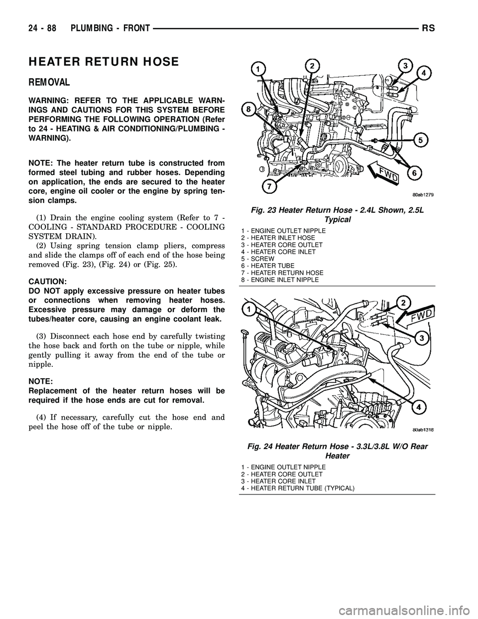
(2) Using spring tension clamp pliers, compress
and slide the clamps off of each end of the hose being
removed (Fig. 23), (Fig. 24) or (Fig. 25).
CAUTION:
DO NOT apply excessive pressure on heater tubes
or connections when removing heater hoses.
Excessive pressure may damage or deform the
tubes/heater core, causing an engine coolant leak.
(3) Disconnect each hose end by carefully twisting
the hose back and forth on the tube or nipple, while
gently pulling it away from the end of the tube or
nipple.
NOTE:
Replacement of the heater return hoses will be
required if the hose ends are cut for removal.
(4) If necessary, carefully cut the hose end and
peel the hose off of the tube or nipple.
Fig. 23 Heater Return Hose - 2.4L Shown, 2.5L
Typical
1 - ENGINE OUTLET NIPPLE
2 - HEATER INLET HOSE
3 - HEATER CORE OUTLET
4 - HEATER CORE INLET
5 - SCREW
6 - HEATER TUBE
7 - HEATER RETURN HOSE
8 - ENGINE INLET NIPPLE
Fig. 24 Heater Return Hose - 3.3L/3.8L W/O Rear
Heater
1 - ENGINE OUTLET NIPPLE
2 - HEATER CORE OUTLET
3 - HEATER CORE INLET
4 - HEATER RETURN TUBE (TYPICAL)
24 - 88 PLUMBING - FRONTRS