2005 CHRYSLER CARAVAN rear view mirror
[x] Cancel search: rear view mirrorPage 1096 of 2339
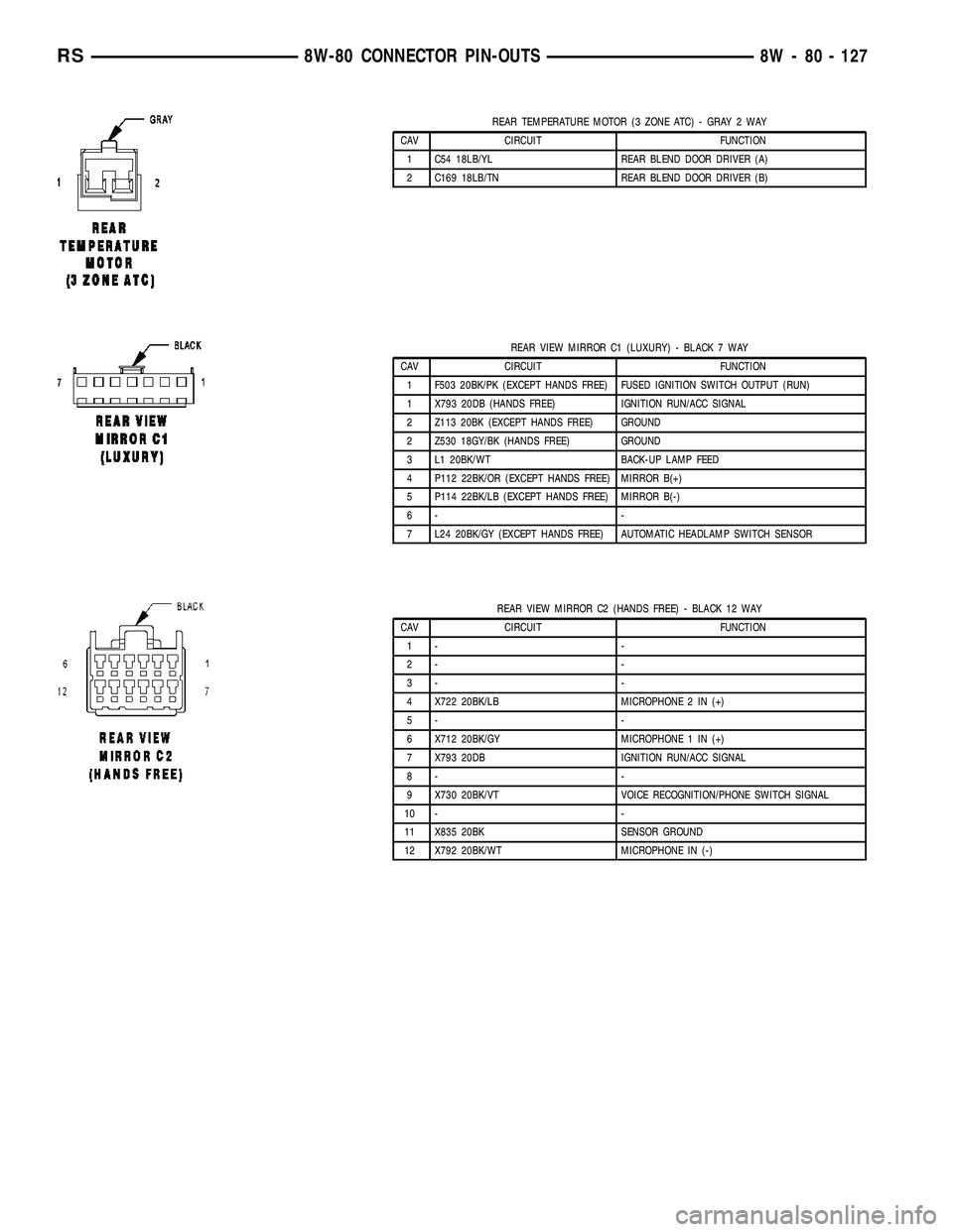
REAR TEMPERATURE MOTOR (3 ZONE ATC) - GRAY 2 WAY
CAV CIRCUIT FUNCTION
1 C54 18LB/YL REAR BLEND DOOR DRIVER (A)
2 C169 18LB/TN REAR BLEND DOOR DRIVER (B)
REAR VIEW MIRROR C1 (LUXURY) - BLACK 7 WAY
CAV CIRCUIT FUNCTION
1 F503 20BK/PK (EXCEPT HANDS FREE) FUSED IGNITION SWITCH OUTPUT (RUN)
1 X793 20DB (HANDS FREE) IGNITION RUN/ACC SIGNAL
2 Z113 20BK (EXCEPT HANDS FREE) GROUND
2 Z530 18GY/BK (HANDS FREE) GROUND
3 L1 20BK/WT BACK-UP LAMP FEED
4 P112 22BK/OR (EXCEPT HANDS FREE) MIRROR B(+)
5 P114 22BK/LB (EXCEPT HANDS FREE) MIRROR B(-)
6- -
7 L24 20BK/GY (EXCEPT HANDS FREE) AUTOMATIC HEADLAMP SWITCH SENSOR
REAR VIEW MIRROR C2 (HANDS FREE) - BLACK 12 WAY
CAV CIRCUIT FUNCTION
1- -
2- -
3- -
4 X722 20BK/LB MICROPHONE 2 IN (+)
5- -
6 X712 20BK/GY MICROPHONE 1 IN (+)
7 X793 20DB IGNITION RUN/ACC SIGNAL
8- -
9 X730 20BK/VT VOICE RECOGNITION/PHONE SWITCH SIGNAL
10 - -
11 X835 20BK SENSOR GROUND
12 X792 20BK/WT MICROPHONE IN (-)
RS8W-80 CONNECTOR PIN-OUTS8W - 80 - 127
Page 1123 of 2339
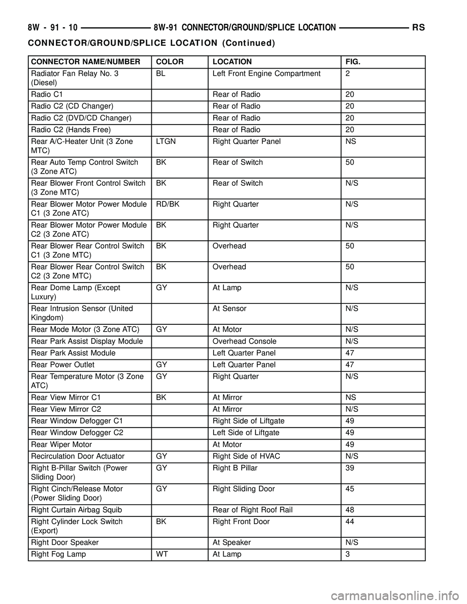
CONNECTOR NAME/NUMBER COLOR LOCATION FIG.
Radiator Fan Relay No. 3
(Diesel)BL Left Front Engine Compartment 2
Radio C1 Rear of Radio 20
Radio C2 (CD Changer) Rear of Radio 20
Radio C2 (DVD/CD Changer) Rear of Radio 20
Radio C2 (Hands Free) Rear of Radio 20
Rear A/C-Heater Unit (3 Zone
MTC)LTGN Right Quarter Panel NS
Rear Auto Temp Control Switch
(3 Zone ATC)BK Rear of Switch 50
Rear Blower Front Control Switch
(3 Zone MTC)BK Rear of Switch N/S
Rear Blower Motor Power Module
C1 (3 Zone ATC)RD/BK Right Quarter N/S
Rear Blower Motor Power Module
C2 (3 Zone ATC)BK Right Quarter N/S
Rear Blower Rear Control Switch
C1 (3 Zone MTC)BK Overhead 50
Rear Blower Rear Control Switch
C2 (3 Zone MTC)BK Overhead 50
Rear Dome Lamp (Except
Luxury)GY At Lamp N/S
Rear Intrusion Sensor (United
Kingdom)At Sensor N/S
Rear Mode Motor (3 Zone ATC) GY At Motor N/S
Rear Park Assist Display Module Overhead Console N/S
Rear Park Assist Module Left Quarter Panel 47
Rear Power Outlet GY Left Quarter Panel 47
Rear Temperature Motor (3 Zone
ATC)GY Right Quarter N/S
Rear View Mirror C1 BK At Mirror NS
Rear View Mirror C2 At Mirror N/S
Rear Window Defogger C1 Right Side of Liftgate 49
Rear Window Defogger C2 Left Side of Liftgate 49
Rear Wiper Motor At Motor 49
Recirculation Door Actuator GY Right Side of HVAC N/S
Right B-Pillar Switch (Power
Sliding Door)GY Right B Pillar 39
Right Cinch/Release Motor
(Power Sliding Door)GY Right Sliding Door 45
Right Curtain Airbag Squib Rear of Right Roof Rail 48
Right Cylinder Lock Switch
(Export)BK Right Front Door 44
Right Door Speaker At Speaker N/S
Right Fog Lamp WT At Lamp 3
8W - 91 - 10 8W-91 CONNECTOR/GROUND/SPLICE LOCATIONRS
CONNECTOR/GROUND/SPLICE LOCATION (Continued)
Page 1127 of 2339
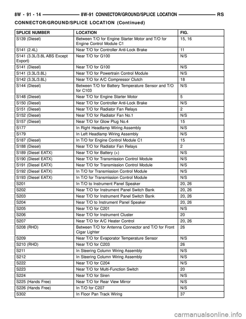
SPLICE NUMBER LOCATION FIG.
S139 (Diesel) Between T/O for Engine Starter Motor and T/O for
Engine Control Module C115, 16
S141 (2.4L) Near T/O for Controller Anti-Lock Brake 11
S141 (3.3L/3.8L ABS Except
Export)Near T/O for G100 N/S
S141 (Diesel) Near T/O for G100 N/S
S141 (3.3L/3.8L) Near T/O for Powertrain Control Module N/S
S142 (3.3L/3.8L) Near T/O for A/C Compressor Clutch 18
S144 (Diesel) Between T/O for Battery Temperature Sensor and T/O
for C103N/S
S148 (Diesel) Near T/O for Engine Starter Motor 5
S150 (Diesel) Near T/O for Controller Anti-Lock Brake N/S
S151 (Diesel) Near T/O for Radiator Fan Relays 2
S152 (Diesel) Near T/O for Radiator Fan No.1 N/S
S157 (Diesel) Near T/O for Glow Plug No.4 15
S177 In Right Headlamp Wiring Assembly N/S
S179 In Left Headlamp Wiring Assembly N/S
S187 (Diesel) In T/O for Engine Control Module C1 15
S188 (Diesel) Near T/O for Radiator Fan Relays 2
S189 (Diesel EATX) Near T/O for Battery (+) N/S
S190 (Diesel EATX) Near T/O for Transmission Control Module N/S
S191 (Diesel EATX) Near T/O for Transmission Control Module N/S
S192 (Diesel EATX) In T/O for Transmission Control Module N/S
S193 (Diesel EATX) In T/O for Transmission Control Module N/S
S201 In T/O to Instrument Panel Speaker 20, 26
S202 Near T/O for Instrument Panel Switch Bank 20, 26
S203 Near T/O for Instrument Panel Switch Bank 20, 26
S204 Near T/O to Instrument Panel Speaker 20, 26
S205 Near T/O for C201 N/S
S206 Near T/O for Instrument Cluster 20
S207 Near T/O for A/C Heater Control 20, 26
S208 (RHD) Between T/O for Antenna Connector and T/O for Front
Cigar Lighter26
S209 Near T/O for Evaporator Temperature Sensor N/S
S210 (RHD) Near T/O for C203 26
S211 In Steering Column Wiring Assembly N/S
S212 In Steering Column Wiring Assembly N/S
S222 Near T/O for C204 N/S
S223 Near T/O for Multi-Function Switch 20
S224 Near T/O for Siren N/S
S225 (Hands Free) Near T/O for Rear View Mirror N/S
S226 (Hands Free) In T/O for C207 N/S
S302 In Floor Pan Track Wiring 37
8W - 91 - 14 8W-91 CONNECTOR/GROUND/SPLICE LOCATIONRS
CONNECTOR/GROUND/SPLICE LOCATION (Continued)
Page 1790 of 2339
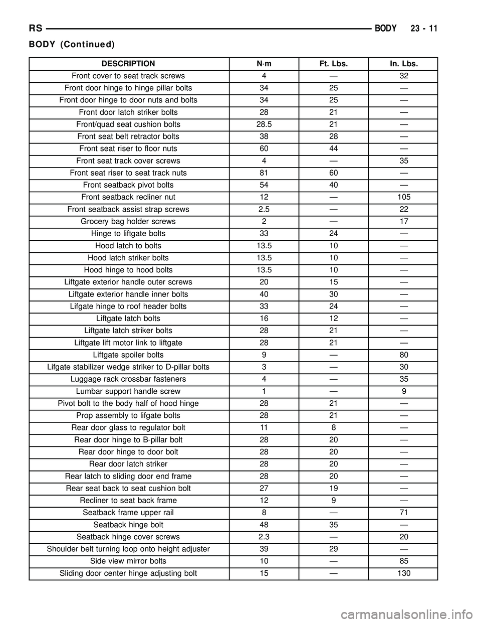
DESCRIPTION N´m Ft. Lbs. In. Lbs.
Front cover to seat track screws 4 Ð 32
Front door hinge to hinge pillar bolts 34 25 Ð
Front door hinge to door nuts and bolts 34 25 Ð
Front door latch striker bolts 28 21 Ð
Front/quad seat cushion bolts 28.5 21 Ð
Front seat belt retractor bolts 38 28 Ð
Front seat riser to floor nuts 60 44 Ð
Front seat track cover screws 4 Ð 35
Front seat riser to seat track nuts 81 60 Ð
Front seatback pivot bolts 54 40 Ð
Front seatback recliner nut 12 Ð 105
Front seatback assist strap screws 2.5 Ð 22
Grocery bag holder screws 2 Ð 17
Hinge to liftgate bolts 33 24 Ð
Hood latch to bolts 13.5 10 Ð
Hood latch striker bolts 13.5 10 Ð
Hood hinge to hood bolts 13.5 10 Ð
Liftgate exterior handle outer screws 20 15 Ð
Liftgate exterior handle inner bolts 40 30 Ð
Lifgate hinge to roof header bolts 33 24 Ð
Liftgate latch bolts 16 12 Ð
Liftgate latch striker bolts 28 21 Ð
Liftgate lift motor link to liftgate 28 21 Ð
Liftgate spoiler bolts 9 Ð 80
Lifgate stabilizer wedge striker to D-pillar bolts 3 Ð 30
Luggage rack crossbar fasteners 4 Ð 35
Lumbar support handle screw 1 Ð 9
Pivot bolt to the body half of hood hinge 28 21 Ð
Prop assembly to lifgate bolts 28 21 Ð
Rear door glass to regulator bolt 11 8 Ð
Rear door hinge to B-pillar bolt 28 20 Ð
Rear door hinge to door bolt 28 20 Ð
Rear door latch striker 28 20 Ð
Rear latch to sliding door end frame 28 20 Ð
Rear seat back to seat cushion bolt 27 19 Ð
Recliner to seat back frame 12 9 Ð
Seatback frame upper rail 8 Ð 71
Seatback hinge bolt 48 35 Ð
Seatback hinge cover screws 2.3 Ð 20
Shoulder belt turning loop onto height adjuster 39 29 Ð
Side view mirror bolts 10 Ð 85
Sliding door center hinge adjusting bolt 15 Ð 130
RSBODY23-11
BODY (Continued)
Page 1824 of 2339
EXTERIOR
TABLE OF CONTENTS
page page
BODY SIDE MOLDINGS
REMOVAL.............................45
INSTALLATION.........................46
COWL GRILLE
REMOVAL.............................50
INSTALLATION.........................50
EXTERIOR NAME PLATES - TAPE ATTACHED
REMOVAL.............................51
INSTALLATION.........................51
EXTERIOR NAME PLATES - ADHESIVE
ATTACHED
REMOVAL.............................51
INSTALLATION.........................51
FRONT FENDER
REMOVAL.............................51
INSTALLATION.........................52
FUEL FILL DOOR
REMOVAL.............................52
INSTALLATION.........................52
FUEL FILL DOOR BLOCKER LATCH
REMOVAL.............................53
INSTALLATION.........................53
FUEL FILL DOOR BLOCKER LATCH STRIKER
REMOVAL.............................53
INSTALLATION.........................53
FUEL FILL DOOR BLOCKER LOCKOUT LINK
REMOVAL.............................54
INSTALLATION.........................54
GRILLE
DESCRIPTION.........................55REMOVAL.............................55
INSTALLATION.........................55
UPPER RADIATOR CROSSMEMBER
REMOVAL.............................56
INSTALLATION.........................56
FRONT WHEELHOUSE SPLASH SHIELD
REMOVAL.............................57
INSTALLATION.........................57
LUGGAGE RACK RISER
REMOVAL.............................57
INSTALLATION.........................58
LUGGAGE RACK CROSSBAR
REMOVAL.............................58
INSTALLATION.........................59
REAR QUARTER PANEL/FENDER AIR
EXHAUSTER
DESCRIPTION.........................59
REMOVAL.............................59
INSTALLATION.........................60
ROOF JOINT MOLDING
REMOVAL.............................60
INSTALLATION.........................60
SIDE VIEW MIRROR
REMOVAL.............................60
INSTALLATION.........................60
GLASS-OUTSIDE REARVIEW MIRROR
REMOVAL.............................61
INSTALLATION.........................61
BODY SIDE MOLDINGS
REMOVAL
Refer to (Fig. 1), (Fig. 2), (Fig. 3), (Fig. 4) or (Fig.
5)for proper location of fasteners holding the molding
to the wheelhouse lip and rocker panels.
(1) Warm the affected stick on molding and body
metal to approximately 38É C (100É F) using a suit-
able heat lamp or heat gun.(2) If equipped, remove pop rivets holding molding
edge to wheelhouse lip.
(3) Pull stick on molding from painted surface.
(4) Remove adhesive tape residue from painted
surface of vehicle. Use a 3M Scotch-BriteŸ Molding
Adhesive and Stripe Removal Disc, or equivalent, to
clean adhesive residue from painted surfaces. These
products are available from automotive paint suppli-
ers. Refer to instructions supplied with the specific
product for proper usage.
RSEXTERIOR23-45
Page 1839 of 2339
INSTALLATION
SHORT WHEELBASE
(1) Position the air exhauster to the hole in the
lower aperture panel (Fig. 21).
(2) Using hand pressure, press the air exhauster
into the opening in the lower aperture panel until
the snap features are fully engaged.
(3) Reinstall the rear fascia onto the body. (Refer
to 13 - FRAMES & BUMPERS/BUMPERS/REAR
FASCIA - INSTALLATION).
LONG WHEELBASE
NOTE: Models with the optional rear heater and air
conditioner do not have an air exhauster on the
right side of the vehicle, but have a plastic plug
installed in the right lower aperture panel. This plug
is installed using the same procedure used to
install the air exhauster onto the short wheelbase
model. Refer to SHORT WHEELBASE.
(1) Position the air exhauster to the hole in the
lower aperture panel (Fig. 22).
(2) Using hand pressure, press the air exhauster
into the opening in the lower aperture panel until
the snap features are fully engaged.
(3) Reinstall the quarter trim panel onto the inside
of the left or right quarter inner panel. (Refer to 23 -
BODY/INTERIOR/RIGHT QUARTER TRIM PANEL
- INSTALLATION) or (Refer to 23 - BODY/INTERI-
OR/LEFT QUARTER TRIM PANEL - INSTALLA-
TION).
ROOF JOINT MOLDING
REMOVAL
The RAP molding is set with body side molding
tape. The temperature in the work area and the vehi-
cle should be at least 21É C (70É F) to avoid damag-
ing the RAP moldings.
(1) Warm the affected stick-on molding and body
metal to approximately 38É C (100É F) using a suit-
able heat lamp or heat gun.
(2) Pull stick-on molding from painted surface.
(3) Remove adhesive tape residue from painted
surface of vehicle. Use a 3M Scotch-BriteŸ Molding
Adhesive and Stripe Removal Discs, or equivalent, to
clean adhesive residue from painted surfaces. The
adhesive removal discs are available from automotive
paint suppliers. Refer to instructions supplied with
the discs for proper usage.
INSTALLATION
The RAP molding is set with body side molding
tape. The temperature in the work area and the vehi-
cle should be at least 21É C (70É F) to avoid damag-
ing the RAP moldings.
(1) If molding is to be reused;
(a) Remove tape residue from molding.
(b) Clean back of molding with MopartSuper
Kleen solvent, or equivalent.
(c) Wipe molding dry with lint free cloth.
(d) Apply new body side molding (two sided
adhesive) tape to back of molding.
(2) Clean body surface with MopartSuper Kleen
solvent, or equivalent. Wipe surface dry with lint free
cloth.
(3) Remove protective cover from tape on back of
molding.
(4) Apply molding to body from front of vehicle to
rear.
(5) Using a roller tool, roll molding onto body
panel with enough force to assure adhesion and not
bend roof panels.
SIDE VIEW MIRROR
REMOVAL
(1) Using a trim stick C-4755 or equivalent, lift up
the end of the instrument panel top pad enough to
gain access to the mirror electrical connector, if
equipped. (Refer to 23 - BODY/INSTRUMENT PAN-
EL/INSTRUMENT PANEL TOP COVER -
REMOVAL)
(2) Disconnect the electrical connector, if equipped.
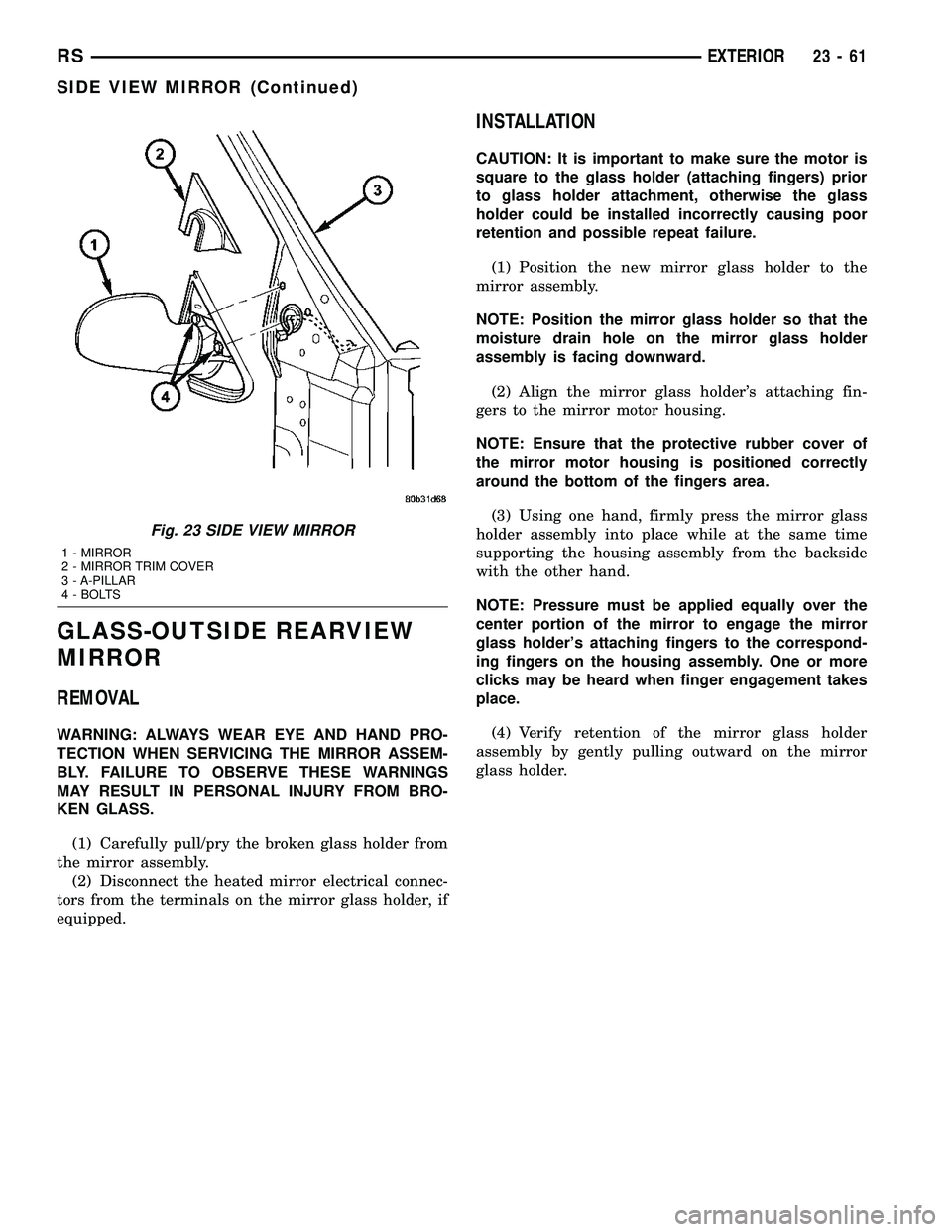
(3) Using a trim stick or equivalent, remove the
trim cover (Fig. 23).
(4) Remove the bolts.
(5) Remove the mirror from the pillar.
INSTALLATION
(1) Route the mirror wire harness, if equipped,
through the a-pillar and place side view mirror in
position on vehicle (Fig. 23).
(2) Install the bolts and tighten to 10 N´m (85 in.
lbs.).
(3) Install the mirror trim cover.
(4) Connect the electrical connector, if equipped.
(5) Install the instrument panel top cover, if
equipped with the electric mirror. (Refer to 23 -
BODY/INSTRUMENT PANEL/INSTRUMENT
PANEL TOP COVER - INSTALLATION)
23 - 60 EXTERIORRS
REAR QUARTER PANEL/FENDER AIR EXHAUSTER (Continued)
Page 1840 of 2339
GLASS-OUTSIDE REARVIEW
MIRROR
REMOVAL
WARNING: ALWAYS WEAR EYE AND HAND PRO-
TECTION WHEN SERVICING THE MIRROR ASSEM-
BLY. FAILURE TO OBSERVE THESE WARNINGS
MAY RESULT IN PERSONAL INJURY FROM BRO-
KEN GLASS.
(1) Carefully pull/pry the broken glass holder from
the mirror assembly.
(2) Disconnect the heated mirror electrical connec-
tors from the terminals on the mirror glass holder, if
equipped.
INSTALLATION
CAUTION: It is important to make sure the motor is
square to the glass holder (attaching fingers) prior
to glass holder attachment, otherwise the glass
holder could be installed incorrectly causing poor
retention and possible repeat failure.
(1) Position the new mirror glass holder to the
mirror assembly.
NOTE: Position the mirror glass holder so that the
moisture drain hole on the mirror glass holder
assembly is facing downward.
(2) Align the mirror glass holder's attaching fin-
gers to the mirror motor housing.
NOTE: Ensure that the protective rubber cover of
the mirror motor housing is positioned correctly
around the bottom of the fingers area.
(3) Using one hand, firmly press the mirror glass
holder assembly into place while at the same time
supporting the housing assembly from the backside
with the other hand.
NOTE: Pressure must be applied equally over the
center portion of the mirror to engage the mirror
glass holder's attaching fingers to the correspond-
ing fingers on the housing assembly. One or more
clicks may be heard when finger engagement takes
place.
(4) Verify retention of the mirror glass holder
assembly by gently pulling outward on the mirror
glass holder.
Fig. 23 SIDE VIEW MIRROR
1 - MIRROR
2 - MIRROR TRIM COVER
3 - A-PILLAR
4 - BOLTS
RSEXTERIOR23-61
SIDE VIEW MIRROR (Continued)
Page 1857 of 2339
INTERIOR
TABLE OF CONTENTS
page page
A-PILLAR LOWER EXTENSION TRIM
REMOVAL.............................79
INSTALLATION.........................79
A-PILLAR TRIM
REMOVAL.............................79
INSTALLATION.........................79
ASSIST HANDLE
REMOVAL.............................79
INSTALLATION.........................79
B-PILLAR LOWER TRIM
REMOVAL.............................79
INSTALLATION.........................80
B-PILLAR UPPER TRIM
REMOVAL.............................80
INSTALLATION.........................80
CARPETS AND FLOOR MATS
REMOVAL.............................81
INSTALLATION.........................81
CARPETS - FOLD-IN-FLOOR
REMOVAL.............................82
INSTALLATION.........................83
CARPET TRIM RING AND COVER - FOLD-IN-
FLOOR
REMOVAL.............................84
INSTALLATION.........................84
COWL TRIM
REMOVAL.............................88
INSTALLATION.........................88
C-PILLAR TRIM
REMOVAL.............................88
INSTALLATION.........................88
DOOR SILL TRIM PLATE
REMOVAL.............................89
INSTALLATION.........................89
FLOOR CONSOLE BASE TRAY
REMOVAL.............................89
INSTALLATION.........................89
FLOOR CONSOLE - FOLD-IN-FLOOR
REMOVAL.............................89
INSTALLATION.........................89
FLOOR CONSOLE KEY LOCK TUMBLER -
FOLD-IN-FLOOR
REMOVAL.............................90
INSTALLATION.........................90
FLOOR CONSOLE LID LATCH - FOLD-IN-
FLOOR
REMOVAL.............................90
INSTALLATION.........................90HEADLINER
REMOVAL.............................91
INSTALLATION.........................92
LEFT D-PILLAR TRIM PANEL
REMOVAL.............................94
INSTALLATION.........................94
LEFT QUARTER TRIM PANEL
REMOVAL.............................94
INSTALLATION.........................94
LIFTGATE SILL PLATE
REMOVAL.............................94
INSTALLATION.........................95
QUARTER TRIM BOLSTER
REMOVAL.............................95
INSTALLATION.........................95
REAR FLOOR TUB CARPETS INSERT -
FOLD-IN-FLOOR
REMOVAL.............................95
INSTALLATION.........................96
REAR HEADER TRIM
REMOVAL.............................96
INSTALLATION.........................96
REAR HVAC LOUVER
REMOVAL.............................96
INSTALLATION.........................97
RIGHT QUARTER TRIM PANEL
REMOVAL.............................97
INSTALLATION.........................97
REAR VIEW MIRROR
REMOVAL.............................97
INSTALLATION.........................97
RIGHT D-PILLAR TRIM PANEL
REMOVAL.............................97
INSTALLATION.........................98
SECOND ROW FLOOR TUB CARPET INSERT -
FOLD-IN-FLOOR
REMOVAL.............................98
INSTALLATION.........................98
SLIDING DOOR SILL PLATE
REMOVAL.............................98
INSTALLATION.........................99
SUN VISOR
REMOVAL.............................99
INSTALLATION.........................99
SUN VISOR SUPPORT
REMOVAL.............................99
INSTALLATION.........................99
23 - 78 INTERIORRS