2005 CHRYSLER CARAVAN glove box
[x] Cancel search: glove boxPage 1852 of 2339
LOWER CONSOLE
REMOVAL
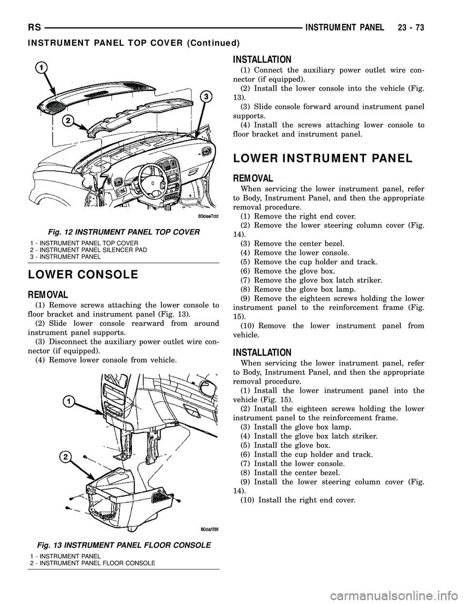
(1) Remove screws attaching the lower console to
floor bracket and instrument panel (Fig. 13).
(2) Slide lower console rearward from around
instrument panel supports.
(3) Disconnect the auxiliary power outlet wire con-
nector (if equipped).
(4) Remove lower console from vehicle.
INSTALLATION
(1) Connect the auxiliary power outlet wire con-
nector (if equipped).
(2) Install the lower console into the vehicle (Fig.
13).
(3) Slide console forward around instrument panel
supports.
(4) Install the screws attaching lower console to
floor bracket and instrument panel.
LOWER INSTRUMENT PANEL
REMOVAL
When servicing the lower instrument panel, refer
to Body, Instrument Panel, and then the appropriate
removal procedure.
(1) Remove the right end cover.
(2) Remove the lower steering column cover (Fig.
14).
(3) Remove the center bezel.
(4) Remove the lower console.
(5) Remove the cup holder and track.
(6) Remove the glove box.
(7) Remove the glove box latch striker.
(8) Remove the glove box lamp.
(9) Remove the eighteen screws holding the lower
instrument panel to the reinforcement frame (Fig.
15).
(10) Remove the lower instrument panel from
vehicle.
INSTALLATION
When servicing the lower instrument panel, refer
to Body, Instrument Panel, and then the appropriate
removal procedure.
(1) Install the lower instrument panel into the
vehicle (Fig. 15).
(2) Install the eighteen screws holding the lower
instrument panel to the reinforcement frame.
(3) Install the glove box lamp.
(4) Install the glove box latch striker.
(5) Install the glove box.
(6) Install the cup holder and track.
(7) Install the lower console.
(8) Install the center bezel.
(9) Install the lower steering column cover (Fig.
14).
(10) Install the right end cover.
Fig. 12 INSTRUMENT PANEL TOP COVER
1 - INSTRUMENT PANEL TOP COVER
2 - INSTRUMENT PANEL SILENCER PAD
3 - INSTRUMENT PANEL
Fig. 13 INSTRUMENT PANEL FLOOR CONSOLE
1 - INSTRUMENT PANEL
2 - INSTRUMENT PANEL FLOOR CONSOLE
RSINSTRUMENT PANEL23-73
INSTRUMENT PANEL TOP COVER (Continued)
Page 1856 of 2339
INSTRUMENT PANEL TOP PAD
ASSEMBLY
REMOVAL
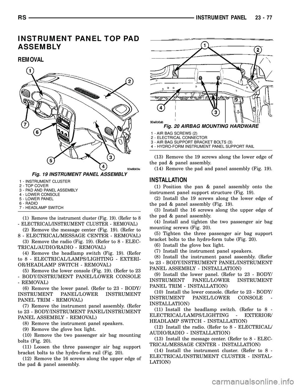
(1)Remove the instrument cluster (Fig. 19). (Refer to 8
- ELECTRICAL/INSTRUMENT CLUSTER - REMOVAL)
(2) Remove the message center (Fig. 19). (Refer to
8 - ELECTRICAL/MESSAGE CENTER - REMOVAL)
(3) Remove the radio (Fig. 19). (Refer to 8 - ELEC-
TRICAL/AUDIO/RADIO - REMOVAL)
(4) Remove the headlamp switch (Fig. 19). (Refer
to 8 - ELECTRICAL/LAMPS/LIGHTING - EXTERI-
OR/HEADLAMP SWITCH - REMOVAL)
(5) Remove the lower console (Fig. 19). (Refer to 23
- BODY/INSTRUMENT PANEL/LOWER CONSOLE
- REMOVAL)
(6) Remove the lower panel. (Refer to 23 - BODY/
INSTRUMENT PANEL/LOWER INSTRUMENT
PANEL TRIM - REMOVAL)
(7) Remove the instrument panel assembly. (Refer
to 23 - BODY/INSTRUMENT PANEL/INSTRUMENT
PANEL ASSEMBLY - REMOVAL)
(8) Remove the instrument panel speakers.
(9) Remove the glove box light.
(10) Remove the two passenger air bag mounting
bolts (Fig. 20).
(11) Loosen the three passenger air bag support
bracket bolts to the hydro-form rail (Fig. 20).
(12) Remove the 16 screws along the upper edge of
the pad & panel assembly.(13) Remove the 19 screws along the lower edge of
the pad & panel assembly.
(14) Remove the pad and panel assembly (Fig. 19).
INSTALLATION
(1) Position the pan & panel assembly onto the
instrument panel support structure (Fig. 19).
(2) Install the 19 screws along the lower edge of
the pad & panel assembly (Fig. 19).
(3) Install the 16 screws along the upper edge of
the pad & panel assembly.
(4) Install and tighten the two passenger air bag
mounting screws (Fig. 20).
(5) Tighten the three passenger air bag support
bracket bolts to the hydro-form tube (Fig. 20).
(6) Install the glove box light.
(7) Install the instrument panel speakers.
(8) Install the instrument panel assembly. (Refer
to 23 - BODY/INSTRUMENT PANEL/INSTRUMENT
PANEL ASSEMBLY - INSTALLATION)
(9) Install the lower panel. (Refer to 23 - BODY/
INSTRUMENT PANEL/LOWER INSTRUMENT
PANEL TRIM - INSTALLATION)
(10) Install the lower console. (Refer to 23 - BODY/
INSTRUMENT PANEL/LOWER CONSOLE -
INSTALLATION)
(11) Install the headlamp switch. (Refer to 8 -
ELECTRICAL/LAMPS/LIGHTING - EXTERIOR/
HEADLAMP SWITCH - INSTALLATION)
(12) Install the radio. (Refer to 8 - ELECTRICAL/
AUDIO/RADIO - INSTALLATION)
(13)
Install the message center. (Refer to 8 - ELEC-
TRICAL/MESSAGE CENTER - INSTALLATION)
(14) Install the instrument cluster. (Refer to 8 -
ELECTRICAL/INSTRUMENT CLUSTER - INSTAL-
LATION)
Fig. 19 INSTRUMENT PANEL ASSEMBLY
1 - INSTRUMENT CLUSTER
2 - TOP COVER
3 - PAD AND PANEL ASSEMBLY
4 - LOWER CONSOLE
5 - LOWER PANEL
6 - RADIO
7 - HEADLAMP SWITCH
Fig. 20 AIRBAG MOUNTING HARDWARE
1 - AIR BAG SCREWS (2)
2 - ELECTRICAL CONNECTOR
3 - AIR BAG SUPPORT BRACKET BOLTS (3)
4 - HYDRO-FORM INSTRUMENT PANEL SUPPORT RAIL
RSINSTRUMENT PANEL23-77
Page 2154 of 2339
²a rotary adjustment knob for temperature.
²a rotary adjustment for fan speed control.
AUTOMATIC TEMPERATURE CONTROL
Two different automatic temperature control (ATC)
heating-A/C systems are available for this model
depending on the market.
The Dual-Zone ATC system allows the driver and
front occupants to each select individual comfort tem-
peratures.
The Three-Zone ATC system allows both the driver
and front occupants and the rear intermediate occu-
pants to select individual comfort temperatures.
NOTE: Individual comfort temperatures are the per-
ceived temperature level at the individual seating
areas, NOT the actual passenger compartment air
temperature.
The ATC system includes a particulate air filter.
The filter element is the same size as the A/C evap-
orator to ensure ample capacity. A door at the base of
the HVAC housing below the glove box provides easy
access to the filter element.
The ATC computer utilizes integrated circuitry and
information carried on the programmable communi-
cations interface (PCI) data bus network to monitor
many sensors and switch inputs throughout the vehi-
cle. In response to those inputs, the internal circuitry
and programming of the ATC computer allow it to
control electronic functions and features of the ATC
system. The inputs to the ATC computer are:
²Vehicle Speed/Engine RPM± The ATC com-
puter monitors engine rpm, vehicle speed and mani-
fold absolute pressure information from the
powertrain control module (PCM).
²Coolant Temperature± ATC computer moni-
tors coolant temperature received from the PCM and
converts it to degrees Fahrenheit.
²Ambient Temperature± ATC computer moni-
tors ambient temperature from the compass mini trip
computer (CMTC) and converts it to degrees Fahren-
heit.
²Engine Miscellaneous Sensor Status±ATC
computer monitors A/C disable information from the
PCM.
²Refrigerant Pressure± ATC computer moni-
tors barometric pressure, intake air temperature,
high side pressure and methanol content as broad-
cast by the PCM.
²Door Ajar Status± The ATC computer moni-
tors driver front door, passenger front door, left rear
door, right rear door and liftgate ajar information, as
identified by the body control module (BCM), to
determine if all in-car temperatures should be main-
tained.²Dimming± The ATC computer monitors dim-
ming status from the BCM to determine the required
level of brightness and will dim accordingly.
²Vehicle Odometer± The ATC computer moni-
tors the vehicle odometer information from the BCM
to prevent flashing the vacuum-flourescent (VF) dig-
ital display icons if the manual motor calibration or
manual cool down tests have failed. Flashing of the
display icons will cease when the vehicle odometer is
greater than 3 miles.
²English/Metric± The ATC computer monitors
the English/Metric information broadcast by the
CMTC. The set temp displays for both the front and
rear control heads will be set accordingly.
²Vehicle Identification Number± The ATC
computer monitors the last eight characters of the
VIN broadcast by the PCM and compares it to the
information stored in EEPROM. If it is different, the
new number will be stored over the old one and a
motor calibration shall be initiated.
²A/C System Information± The ATC computer
will send a message for evaporator temperature too
low, fan blower relay status, evaporator sensor fail-
ure, rear window defogger relay and A/C select.
FRONT CONTROL PANEL
The front A/C-heater control and integral computer
is mounted in the instrument panel and contains:
²a power button which allows the system to be
completely turned off. The display is blank when the
system is off.
²a rocker switch that selects a cool-down rate.
LO-AUTO or HI-AUTO are displayed when the sys-
tem is in automatic operation.
²three rocker switches that select comfort temper-
atures from 15É to 30É C (59É to 85É F), which are
shown in the VF digital display. If the set temp is 15É
C (59É F) and the down button is pressed, the set
temp value will become 13É C (55É F) but the display
will show LO. If the set temp is 29É C (85É F) and the
up button is pressed, the set temp value will become
32É C (90É F) but the display will show HIGH. Tem-
peratures can be displayed in either metric or Fahr-
enheit, which is controlled from the overhead console.
²an air conditioning button that allows the com-
pressor to be turned off. A Snowflake symbol is illu-
minated when air conditioning is on, whether under
manual or automatic control.
²an air recirculation button. A Recirculation sym-
bol appears in the display when the button is
pressed, or when the system exceeds 80 percent recir-
culated air under automatic control due to high air
conditioning demand.
²a rear window defogger on/off switch. A graphic
symbol shows when the defroster is on.
RSHEATING & AIR CONDITIONING24-3
HEATING & AIR CONDITIONING (Continued)
Page 2170 of 2339
REMOVAL
(1) Disconnect and isolate the negative battery
cable.
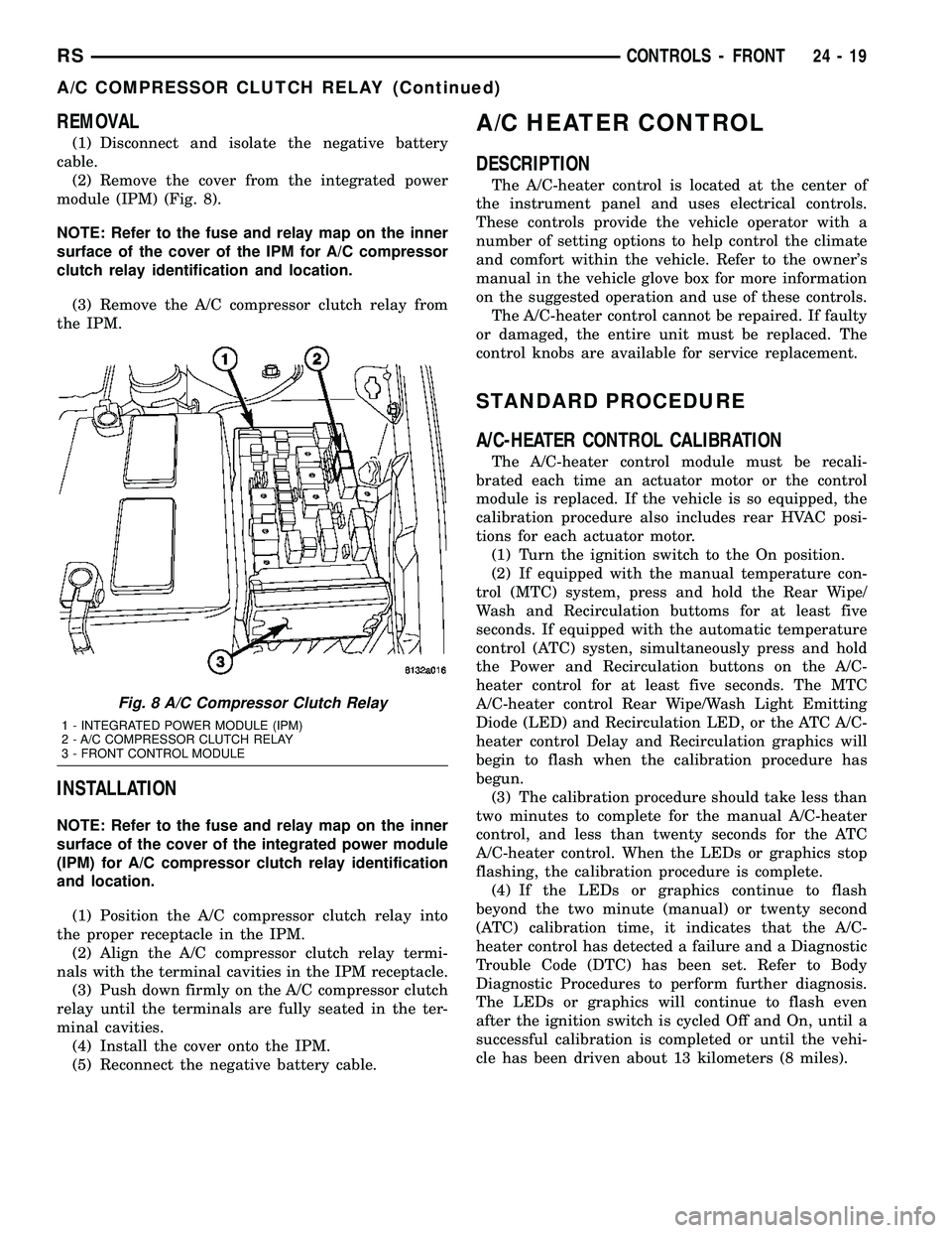
(2) Remove the cover from the integrated power
module (IPM) (Fig. 8).
NOTE: Refer to the fuse and relay map on the inner
surface of the cover of the IPM for A/C compressor
clutch relay identification and location.
(3) Remove the A/C compressor clutch relay from
the IPM.
INSTALLATION
NOTE: Refer to the fuse and relay map on the inner
surface of the cover of the integrated power module
(IPM) for A/C compressor clutch relay identification
and location.
(1) Position the A/C compressor clutch relay into
the proper receptacle in the IPM.
(2) Align the A/C compressor clutch relay termi-
nals with the terminal cavities in the IPM receptacle.
(3) Push down firmly on the A/C compressor clutch
relay until the terminals are fully seated in the ter-
minal cavities.
(4) Install the cover onto the IPM.
(5) Reconnect the negative battery cable.
A/C HEATER CONTROL
DESCRIPTION
The A/C-heater control is located at the center of
the instrument panel and uses electrical controls.
These controls provide the vehicle operator with a
number of setting options to help control the climate
and comfort within the vehicle. Refer to the owner's
manual in the vehicle glove box for more information
on the suggested operation and use of these controls.
The A/C-heater control cannot be repaired. If faulty
or damaged, the entire unit must be replaced. The
control knobs are available for service replacement.
STANDARD PROCEDURE
A/C-HEATER CONTROL CALIBRATION
The A/C-heater control module must be recali-
brated each time an actuator motor or the control
module is replaced. If the vehicle is so equipped, the
calibration procedure also includes rear HVAC posi-
tions for each actuator motor.
(1) Turn the ignition switch to the On position.
(2) If equipped with the manual temperature con-
trol (MTC) system, press and hold the Rear Wipe/
Wash and Recirculation buttoms for at least five
seconds. If equipped with the automatic temperature
control (ATC) systen, simultaneously press and hold
the Power and Recirculation buttons on the A/C-
heater control for at least five seconds. The MTC
A/C-heater control Rear Wipe/Wash Light Emitting
Diode (LED) and Recirculation LED, or the ATC A/C-
heater control Delay and Recirculation graphics will
begin to flash when the calibration procedure has
begun.
(3) The calibration procedure should take less than
two minutes to complete for the manual A/C-heater
control, and less than twenty seconds for the ATC
A/C-heater control. When the LEDs or graphics stop
flashing, the calibration procedure is complete.
(4) If the LEDs or graphics continue to flash
beyond the two minute (manual) or twenty second
(ATC) calibration time, it indicates that the A/C-
heater control has detected a failure and a Diagnostic
Trouble Code (DTC) has been set. Refer to Body
Diagnostic Procedures to perform further diagnosis.
The LEDs or graphics will continue to flash even
after the ignition switch is cycled Off and On, until a
successful calibration is completed or until the vehi-
cle has been driven about 13 kilometers (8 miles).
Fig. 8 A/C Compressor Clutch Relay
1 - INTEGRATED POWER MODULE (IPM)
2 - A/C COMPRESSOR CLUTCH RELAY
3 - FRONT CONTROL MODULE
RSCONTROLS - FRONT24-19
A/C COMPRESSOR CLUTCH RELAY (Continued)
Page 2175 of 2339

The blower motor relay terminals are connected to
the vehicle electrical system through a receptacle in
the Integrated Power Module (IPM). The inputs and
outputs of the blower motor relay include:
²The common feed terminal (30) receives a bat-
tery current input from the battery through a B(+)
circuit at all times.
²The coil ground terminal (85) receives a ground
input through the front/rear blower motor relay con-
trol circuit only when the FCM electronically pulls
the control circuit to ground.
²The coil battery terminal (86) receives a battery
current input from the battery through a B(+) circuit
at all times.
²The normally open terminal (87) provides a bat-
tery current output to the blower motor resistor
(manual heater-A/C control) or blower power module
(automatic heater-A/C control) through a fuse in the
IPM on the fused front blower motor relay output cir-
cuit only when the blower motor relay coil is ener-
gized.
²The normally closed terminal (87A) is not con-
nected to any circuit in this application, but provides
a battery current output only when the blower motor
relay coil is de-energized.
Refer to the appropriate wiring information for
diagnosis and testing of the micro-relay and for com-
plete HVAC wiring diagrams.
REMOVAL
(1) Disconnect and isolate the negative battery
cable.
(2) Remove the cover from the integrated power
module (IPM) (Fig. 13).
NOTE: Refer to the fuse and relay map on the inner
surface of the cover of the IPM for front blower
motor relay identification and location.
(3) Remove the front blower motor relay from the
IPM
INSTALLATION
NOTE: Refer to the fuse and relay map on the inner
surface of the cover of the integrated power module
(IPM) for front blower motor relay identification and
location.
(1) Position the front blower motor relay to the
proper receptacle in the IPM.
(2) Align the front blower motor relay terminals
with the terminal cavities in the IPM receptacle.
(3) Push down firmly on the front blower motor
relay until the terminals are fully seated in the ter-
minal cavities.
(4) Install the cover onto the IPM.(5) Reconnect the negative battery cable.
BLOWER MOTOR RESISTOR
BLOCK
DESCRIPTION
A blower motor resistor is used on this model when
it is equipped with the manual heater-A/C system.
Models equipped with the optional Automatic Tem-
perature Control (ATC) system use a blower power
module, instead of the blower motor resistor block
(Refer to 24 - HEATING & AIR CONDITIONING/
CONTROLS/POWER MODULE - DESCRIPTION).
The blower motor resistor block is mounted to the
rear of the HVAC housing, directly behind the glove
box opening in the instrument panel. The resistor
block consists of a molded plastic mounting plate
with two integral connector receptacles. Concealed
behind the mounting plate are four coiled resistor
wires contained within a protective stamped steel
cage. The blower motor resistor block is accessed for
service by removing the glove box from the instru-
ment panel.
OPERATION
The blower motor resistor block is connected to the
vehicle electrical system through a dedicated take
out and connector of the instrument panel wire har-
ness. A second connector receptacle receives the pig-
tail wire connector from the blower motor. The
blower motor resistor has multiple resistor wires,
Fig. 13 Front Blower Motor Relay
1 - INTEGRATED POWER MODULE (IPM)
2 - FRONT BLOWER MOTOR RELAY
2 - FRONT CONTROL MODULE (FCM)
24 - 24 CONTROLS - FRONTRS
BLOWER MOTOR RELAY (Continued)
Page 2176 of 2339
each of which will reduce the current flow through
the blower motor to change the blower motor speed.
The blower motor switch in the manual heater-A/C
system directs the ground path for the blower motor
through the correct resistor wire to obtain the
selected speed.
With the blower motor switch in the lowest speed
position, the ground path for the motor is applied
through all of the resistor wires. Each higher speed
selected with the blower motor switch applies the
blower motor ground path through fewer of the resis-
tor wires, increasing the blower motor speed.
The blower motor resistor cannot be adjusted or
repaired and, if faulty or damaged, it must be
replaced.
DIAGNOSIS AND TESTING
FRONT BLOWER MOTOR RESISTOR BLOCK
WARNING: ON VEHICLES EQUIPPED WITH AIR-
BAGS, DISABLE THE AIRBAG SYSTEM BEFORE
ATTEMPTING ANY STEERING WHEEL, STEERING
COLUMN, OR INSTRUMENT PANEL COMPONENT
DIAGNOSIS OR SERVICE. DISCONNECT AND ISO-
LATE THE BATTERY NEGATIVE (GROUND) CABLE,
THEN WAIT TWO MINUTES FOR THE AIRBAG SYS-
TEM CAPACITOR TO DISCHARGE BEFORE PER-
FORMING FURTHER DIAGNOSIS OR SERVICE. THIS
IS THE ONLY SURE WAY TO DISABLE THE AIRBAG
SYSTEM. FAILURE TO TAKE THE PROPER PRE-
CAUTIONS COULD RESULT IN ACCIDENTAL AIR-
BAG DEPLOYMENT AND POSSIBLE PERSONAL
INJURY.
For circuit descriptions and diagrams, refer to the
appropriate wiring information. The wiring informa-
tion includes wiring diagrams, proper wire and con-
nector repair procedures, further details on wire
harness routing and retention, as well as pin-out and
location views for the various wire harness connec-
tors, splices and grounds.
(1) Disconnect and isolate the battery negative
cable.
(2) Remove the glove box from the instrument
panel (Refer to 23 - BODY/INSTRUMENT PANEL/
GLOVE BOX - REMOVAL).
(3) Disconnect the two wire harness connectors
from the blower motor resistor block.
(4) Check for continuity between each of the
blower motor switch input terminals of the resistor
and the resistor output terminal. In each case there
should be continuity. If OK, repair the wire harness
circuits between the blower motor switch and the
blower motor resistor, blower motor or blower motorrelay as required. If not OK, replace the faulty
blower motor resistor block.
REMOVAL
WARNING: ON VEHICLES EQUIPPED WITH AIR-
BAGS, DISABLE THE AIRBAG SYSTEM BEFORE
ATTEMPTING ANY STEERING WHEEL, STEERING
COLUMN, OR INSTRUMENT PANEL COMPONENT
DIAGNOSIS OR SERVICE. DISCONNECT AND ISO-
LATE THE BATTERY NEGATIVE (GROUND) CABLE,
THEN WAIT TWO MINUTES FOR THE AIRBAG SYS-
TEM CAPACITOR TO DISCHARGE BEFORE PER-
FORMING FURTHER DIAGNOSIS OR SERVICE. THIS
IS THE ONLY SURE WAY TO DISABLE THE AIRBAG
SYSTEM. FAILURE TO TAKE THE PROPER PRE-
CAUTIONS COULD RESULT IN ACCIDENTAL AIR-
BAG DEPLOYMENT AND POSSIBLE PERSONAL
INJURY.
WARNING: THE BLOWER MOTOR RESISTOR
BLOCK MAY GET VERY HOT DURING NORMAL
OPERATION. IF THE BLOWER MOTOR WAS
TURNED ON PRIOR TO SERVICING THE BLOWER
MOTOR RESISTOR BLOCK, WAIT FIVE MINUTES
TO ALLOW THE BLOWER MOTOR RESISTORS TO
COOL BEFORE PERFORMING DIAGNOSIS OR SER-
VICE. FAILURE TO TAKE THIS PRECAUTION CAN
RESULT IN PERSONAL INJURY.
CAUTION: Do not operate the blower motor with the
blower motor resistor removed from the circuit.
Failure to take this precaution can result in vehicle
damage.
(1) Disconnect and isolate the battery negative
cable.
(2) Remove the glove box from the instrument
panel (Refer to 23 - BODY/INSTRUMENT PANEL/
GLOVE BOX - REMOVAL).
(3) Disconnect the two wire harness connectors
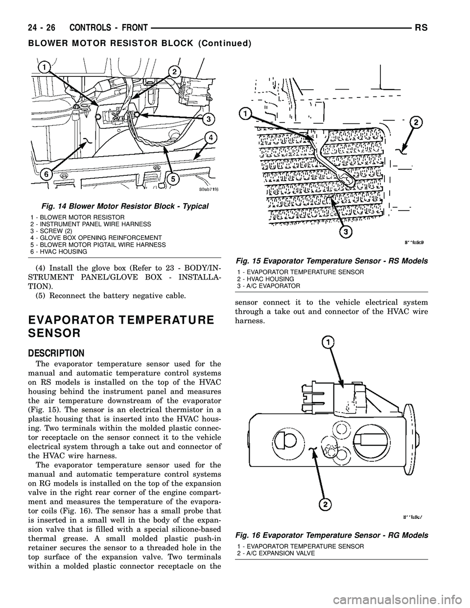
from the blower motor resistor block (Fig. 14).
(4) Remove the two screws that secure the blower
motor resistor block to the HVAC housing.
(5) Remove the resistor block from the HVAC
housing.
INSTALLATION
(1) Position the blower motor resistor block into
the HVAC housing.
(2) Install the two screws that secure the blower
motor resistor block to the HVAC housing. Tighten
the screws to 2 N´m (17 in. lbs.).
(3) Connect the two wire connectors to the resistor
block.
RSCONTROLS - FRONT24-25
BLOWER MOTOR RESISTOR BLOCK (Continued)
Page 2177 of 2339
(4) Install the glove box (Refer to 23 - BODY/IN-
STRUMENT PANEL/GLOVE BOX - INSTALLA-
TION).
(5) Reconnect the battery negative cable.
EVAPORATOR TEMPERATURE
SENSOR
DESCRIPTION
The evaporator temperature sensor used for the
manual and automatic temperature control systems
on RS models is installed on the top of the HVAC
housing behind the instrument panel and measures
the air temperature downstream of the evaporator
(Fig. 15). The sensor is an electrical thermistor in a
plastic housing that is inserted into the HVAC hous-
ing. Two terminals within the molded plastic connec-
tor receptacle on the sensor connect it to the vehicle
electrical system through a take out and connector of
the HVAC wire harness.
The evaporator temperature sensor used for the
manual and automatic temperature control systems
on RG models is installed on the top of the expansion
valve in the right rear corner of the engine compart-
ment and measures the temperature of the evapora-
tor coils (Fig. 16). The sensor has a small probe that
is inserted in a small well in the body of the expan-
sion valve that is filled with a special silicone-based
thermal grease. A small molded plastic push-in
retainer secures the sensor to a threaded hole in the
top surface of the expansion valve. Two terminals
within a molded plastic connector receptacle on thesensor connect it to the vehicle electrical system
through a take out and connector of the HVAC wire
harness.
Fig. 14 Blower Motor Resistor Block - Typical
1 - BLOWER MOTOR RESISTOR
2 - INSTRUMENT PANEL WIRE HARNESS
3 - SCREW (2)
4 - GLOVE BOX OPENING REINFORCEMENT
5 - BLOWER MOTOR PIGTAIL WIRE HARNESS
6 - HVAC HOUSING
Fig. 15 Evaporator Temperature Sensor - RS Models
1 - EVAPORATOR TEMPERATURE SENSOR
2 - HVAC HOUSING
3 - A/C EVAPORATOR
Fig. 16 Evaporator Temperature Sensor - RG Models
1 - EVAPORATOR TEMPERATURE SENSOR
2 - A/C EXPANSION VALVE
24 - 26 CONTROLS - FRONTRS
BLOWER MOTOR RESISTOR BLOCK (Continued)
Page 2181 of 2339
INSTALLATION
(1) Position the mode door actuator onto the HVAC
distribution housing. If necessary, rotate the actuator
slightly to align the splines on the actuator output
shaft with those in the mode door linkage.
(2) Install the two screws that secure the mode
door actuator to the distribution housing. Tighten the
screws to 2 N´m (17 in. lbs.).
(3) Connect the wire harness connector to the
mode door actuator.
(4) Install the silencer under the driver side end of
the instrument panel (Refer to 23 - BODY/INSTRU-
MENT PANEL/INSTRUMENT PANEL SILENCER -
INSTALLATION).
(5) Reconnect the negative battery cable.
(6) Perform the A/C-heater control calibration pro-
cedure (Refer to 24 - HEATING & AIR CONDITION-
ING/CONTROLS - FRONT/A/C-HEATER CONTROL
- STANDARD PROCEDURE - HEATER-A/C CON-
TROL CALIBRATION).
POWER MODULE - BLOWER
MOTOR
DESCRIPTION
A blower motor power module is used on this
model when it is equipped with the optional Auto-
matic Temperature Control (ATC) system. Models
equipped with the standard manual heater-A/C sys-
tem use a blower motor resistor block, instead of the
blower motor power module (Refer to 24 - HEATING
& AIR CONDITIONING/CONTROLS/BLOWER
MOTOR RESISTOR BLOCK - DESCRIPTION).
The blower motor power module is mounted to the
rear of the HVAC housing, directly behind the glove
box opening in the instrument panel. The module
consists of a molded plastic mounting plate with two
integral connector receptacles. Concealed behind the
mounting plate is the power module electronic cir-
cuitry and a large finned, heat sink. The blower
motor power module is accessed for service by remov-
ing the glove box from the instrument panel.
OPERATION
The blower motor power module is connected to the
vehicle electrical system through a dedicated lead
and connector from the instrument panel wire har-
ness. A second connector receptacle receives a wire
lead connector from the blower motor. The blower
motor power module allows the microprocessor-based
Automatic Temperature Control (ATC) heater-A/C
control module to calculate and provide infinitely
variable blower motor speeds based upon either man-
ual blower switch input or the ATC programming
using a Pulse Width Modulated (PWM) circuit strat-
egy. The PWM voltage is applied to a comparator cir-
cuit which compares the PWM signal voltage to the
blower motor feedback voltage. The resulting output
drives the power module circuitry, which adjusts the
voltage output received from the blower motor relay
to change or maintain the desired blower speed. The
blower motor power module is diagnosed using a
DRBIIItscan tool. Refer to Body Diagnostic Proce-
dures.
REMOVAL
WARNING: ON VEHICLES EQUIPPED WITH AIR-
BAGS, DISABLE THE AIRBAG SYSTEM BEFORE
ATTEMPTING ANY STEERING WHEEL, STEERING
COLUMN, OR INSTRUMENT PANEL COMPONENT
DIAGNOSIS OR SERVICE. DISCONNECT AND ISO-
LATE THE BATTERY NEGATIVE (GROUND) CABLE,
THEN WAIT TWO MINUTES FOR THE AIRBAG SYS-
TEM CAPACITOR TO DISCHARGE BEFORE PER-
FORMING FURTHER DIAGNOSIS OR SERVICE. THIS
IS THE ONLY SURE WAY TO DISABLE THE AIRBAG
SYSTEM. FAILURE TO TAKE THE PROPER PRE-
CAUTIONS COULD RESULT IN ACCIDENTAL AIR-
BAG DEPLOYMENT AND POSSIBLE PERSONAL
INJURY.
WARNING: THE HEAT SINK FOR THE BLOWER
MOTOR POWER MODULE MAY GET VERY HOT
DURING NORMAL OPERATION. IF THE BLOWER
MOTOR WAS TURNED ON PRIOR TO SERVICING
THE BLOWER MOTOR POWER MODULE, WAIT
FIVE MINUTES TO ALLOW THE HEAT SINK TO
COOL BEFORE PERFORMING DIAGNOSIS OR SER-
VICE. FAILURE TO TAKE THIS PRECAUTION CAN
RESULT IN PERSONAL INJURY.
24 - 30 CONTROLS - FRONTRS
MODE DOOR ACTUATOR (Continued)