2005 CHRYSLER CARAVAN check transmission fluid
[x] Cancel search: check transmission fluidPage 1543 of 2339
FLUID
STANDARD PROCEDURE
FLUID LEVEL AND CONDITION CHECK
NOTE: Only transmission fluid of the type labeled
Mopar ATF+4 (Automatic Transmission Fluid)
should be used in this transaxle.
FLUID LEVEL CHECK
The transmission sump has a fluid level indicator
(dipstick) to check oil similar to most automatic
transmissions. It is located on the left side of the
engine. Be sure to wipe all dirt from dipstick handle
before removing.
The torque converter fills in both the P Park and N
Neutral positions. Place the selector lever in P Park
to be sure that the fluid level check is accurate.The
engine should be running at idle speed for at
least one minute, with the vehicle on level
ground.At normal operating temperature 82É C
(180É F), the fluid level is correct if it is in the HOT
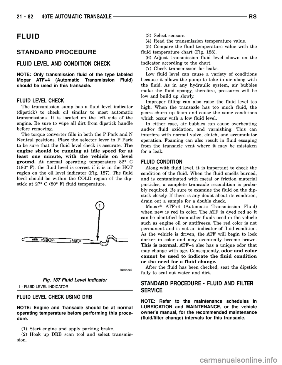
region on the oil level indicator (Fig. 187). The fluid
level should be within the COLD region of the dip-
stick at 27É C (80É F) fluid temperature.
FLUID LEVEL CHECK USING DRB
NOTE: Engine and Transaxle should be at normal
operating temperature before performing this proce-
dure.
(1) Start engine and apply parking brake.
(2) Hook up DRB scan tool and select transmis-
sion.(3) Select sensors.
(4) Read the transmission temperature value.
(5) Compare the fluid temperature value with the
fluid temperature chart (Fig. 188).
(6) Adjust transmission fluid level shown on the
indicator according to the chart.
(7) Check transmission for leaks.
Low fluid level can cause a variety of conditions
because it allows the pump to take in air along with
the fluid. As in any hydraulic system, air bubbles
make the fluid spongy, therefore, pressures will be
low and build up slowly.
Improper filling can also raise the fluid level too
high. When the transaxle has too much fluid, the
gears churn up foam and cause the same conditions
which occur with a low fluid level.
In either case, air bubbles can cause overheating
and/or fluid oxidation, and varnishing. This can
interfere with normal valve, clutch, and accumulator
operation. Foaming can also result in fluid escaping
from the transaxle vent where it may be mistaken
for a leak.
FLUID CONDITION
Along with fluid level, it is important to check the
condition of the fluid. When the fluid smells burned,
and is contaminated with metal or friction material
particles, a complete transaxle recondition is proba-
bly required. Be sure to examine the fluid on the dip-
stick closely. If there is any doubt about its condition,
drain out a sample for a double check.
MopartATF+4 (Automatic Transmission Fluid)
when new is red in color. The ATF is dyed red so it
can be identified from other fluids used in the vehicle
such as engine oil or antifreeze. The red color is not
permanent and is not an indicator of fluid condition.
As the vehicle is driven, the ATF will begin to look
darker in color and may eventually become brown.
This is normal.ATF+4 also has a unique odor that
may change with age. Consequently,odor and color
cannot be used to indicate the fluid condition
or the need for a fluid change.
After the fluid has been checked, seat the dipstick
fully to seal out water and dirt.
STANDARD PROCEDURE - FLUID AND FILTER
SERVICE
NOTE: Refer to the maintenance schedules in
LUBRICATION and MAINTENANCE, or the vehicle
owner's manual, for the recommended maintenance
(fluid/filter change) intervals for this transaxle.
Fig. 187 Fluid Level Indicator
1 - FLUID LEVEL INDICATOR
21 - 82 40TE AUTOMATIC TRANSAXLERS
Page 1545 of 2339
(6) Start engine and allow to idle for at least one
minute. Then, with parking and service brakes
applied, move selector lever momentarily to each
position, ending in the park or neutral position.
(7) Check the transaxle fluid level and add an
appropriate amount to bring the transaxle fluid level
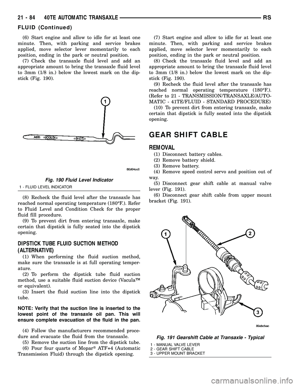
to 3mm (1/8 in.) below the lowest mark on the dip-
stick (Fig. 190).
(8) Recheck the fluid level after the transaxle has
reached normal operating temperature (180ÉF.). Refer
to Fluid Level and Condition Check for the proper
fluid fill procedure.
(9) To prevent dirt from entering transaxle, make
certain that dipstick is fully seated into the dipstick
opening.
DIPSTICK TUBE FLUID SUCTION METHOD
(ALTERNATIVE)
(1) When performing the fluid suction method,
make sure the transaxle is at full operating temper-
ature.
(2) To perform the dipstick tube fluid suction
method, use a suitable fluid suction device (VaculaŸ
or equivalent).
(3) Insert the fluid suction line into the dipstick
tube.
NOTE: Verify that the suction line is inserted to the
lowest point of the transaxle oil pan. This will
ensure complete evacuation of the fluid in the pan.
(4) Follow the manufacturers recommended proce-
dure and evacuate the fluid from the transaxle.
(5) Remove the suction line from the dipstick tube.
(6) Pour four quarts of MopartATF+4 (Automatic
Transmission Fluid) through the dipstick opening.(7) Start engine and allow to idle for at least one
minute. Then, with parking and service brakes
applied, move selector lever momentarily to each
position, ending in the park or neutral position.
(8) Check the transaxle fluid level and add an
appropriate amount to bring the transaxle fluid level
to 3mm (1/8 in.) below the lowest mark on the dip-
stick (Fig. 190).
(9) Recheck the fluid level after the transaxle has
reached normal operating temperature (180ÉF.).
(Refer to 21 - TRANSMISSION/TRANSAXLE/AUTO-
MATIC - 41TE/FLUID - STANDARD PROCEDURE)
(10) To prevent dirt from entering transaxle, make
certain that dipstick is fully seated into the dipstick
opening.
GEAR SHIFT CABLE
REMOVAL
(1) Disconnect battery cables.
(2) Remove battery shield.
(3) Remove battery.
(4) Remove speed control servo and position out of
way.
(5) Disconnect gear shift cable at manual valve
lever (Fig. 191).
(6) Disconnect gear shift cable from upper mount
bracket (Fig. 191).
Fig. 190 Fluid Level Indicator
1 - FLUID LEVEL INDICATOR
Fig. 191 Gearshift Cable at Transaxle - Typical
1 - MANUAL VALVE LEVER
2 - GEAR SHIFT CABLE
3 - UPPER MOUNT BRACKET
21 - 84 40TE AUTOMATIC TRANSAXLERS
FLUID (Continued)
Page 1590 of 2339
TORQUE CONVERTER CLUTCH (TCC)
In a standard torque converter, the impeller and
turbine are rotating at about the same speed and the
stator is freewheeling, providing no torque multipli-
cation. By applying the turbine's piston to the front
cover's friction material, a total converter engage-
ment can be obtained. The result of this engagement
is a direct 1:1 mechanical link between the engine
and the transmission.
The engagement and disengagement of the TCC
are automatic and controlled by the Powertrain Con-
trol Module (PCM). The engagement cannot be acti-
vated in the lower gears because it eliminates the
torque multiplication effect of the torque converter
necessary for acceleration. Inputs that determine
clutch engagement are: coolant temperature, vehicle
speed and throttle position. The torque converter
clutch is engaged by the clutch solenoid on the valve
body. The clutch will engage at approximately 56
km/h (35 mph) with light throttle, after the shift to
third gear.
REMOVAL
(1) Remove transmission and torque converter
from vehicle. (Refer to 21 - TRANSMISSION/TRANS-
AXLE/AUTOMATIC - 41TE - REMOVAL)
(2) Place a suitable drain pan under the converter
housing end of the transmission.
CAUTION: Verify that transmission is secure on the
lifting device or work surface, the center of gravity
of the transmission will shift when the torque con-
verter is removed creating an unstable condition.
The torque converter is a heavy unit. Use caution
when separating the torque converter from the
transmission.
(3) Pull the torque converter forward until the cen-
ter hub clears the oil pump seal.
(4) Separate the torque converter from the trans-
mission.
INSTALLATION
Check converter hub and drive notches for sharp
edges, burrs, scratches, or nicks. Polish the hub and
notches with 320/400 grit paper or crocus cloth if nec-
essary. The hub must be smooth to avoid damaging
the pump seal at installation.
(1) Lubricate converter hub and oil pump seal lip
with transmission fluid.(2) Place torque converter in position on transmis-
sion.
CAUTION: Do not damage oil pump seal or bushing
while inserting torque converter into the front of the
transmission.
(3) Align torque converter to oil pump seal open-
ing.
(4) Insert torque converter hub into oil pump.
(5) While pushing torque converter inward, rotate
converter until converter is fully seated in the oil
pump gears.
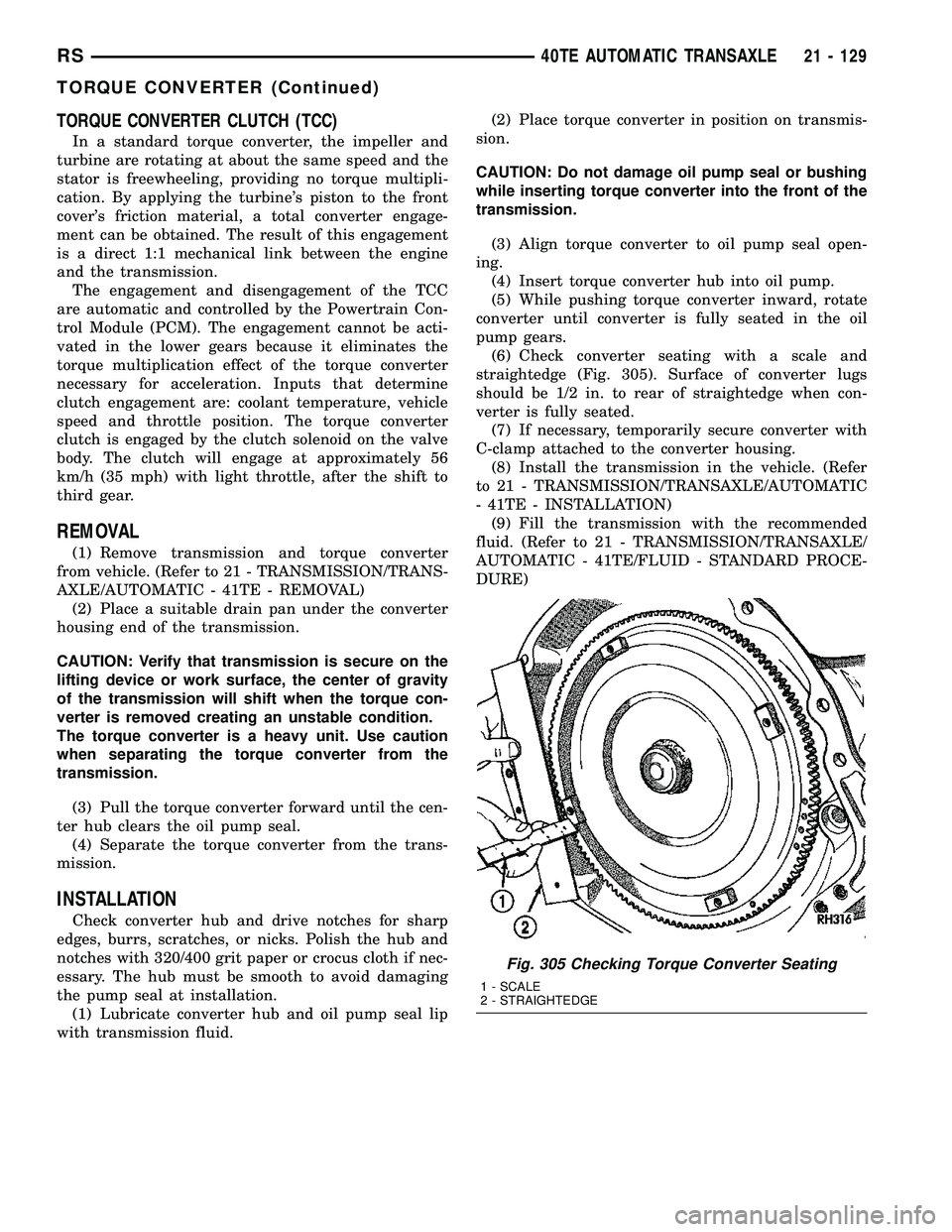
(6) Check converter seating with a scale and
straightedge (Fig. 305). Surface of converter lugs
should be 1/2 in. to rear of straightedge when con-
verter is fully seated.
(7) If necessary, temporarily secure converter with
C-clamp attached to the converter housing.
(8) Install the transmission in the vehicle. (Refer
to 21 - TRANSMISSION/TRANSAXLE/AUTOMATIC
- 41TE - INSTALLATION)
(9) Fill the transmission with the recommended
fluid. (Refer to 21 - TRANSMISSION/TRANSAXLE/
AUTOMATIC - 41TE/FLUID - STANDARD PROCE-
DURE)
Fig. 305 Checking Torque Converter Seating
1 - SCALE
2 - STRAIGHTEDGE
RS40TE AUTOMATIC TRANSAXLE21 - 129
TORQUE CONVERTER (Continued)
Page 1593 of 2339
VALVE BODY
DESCRIPTION
The valve body assembly consists of a cast alumi-
num valve body, a separator plate, and transfer
plate. The valve body contains valves and check balls
that control fluid delivery to the torque converter
clutch, solenoid/pressure switch assembly, and fric-
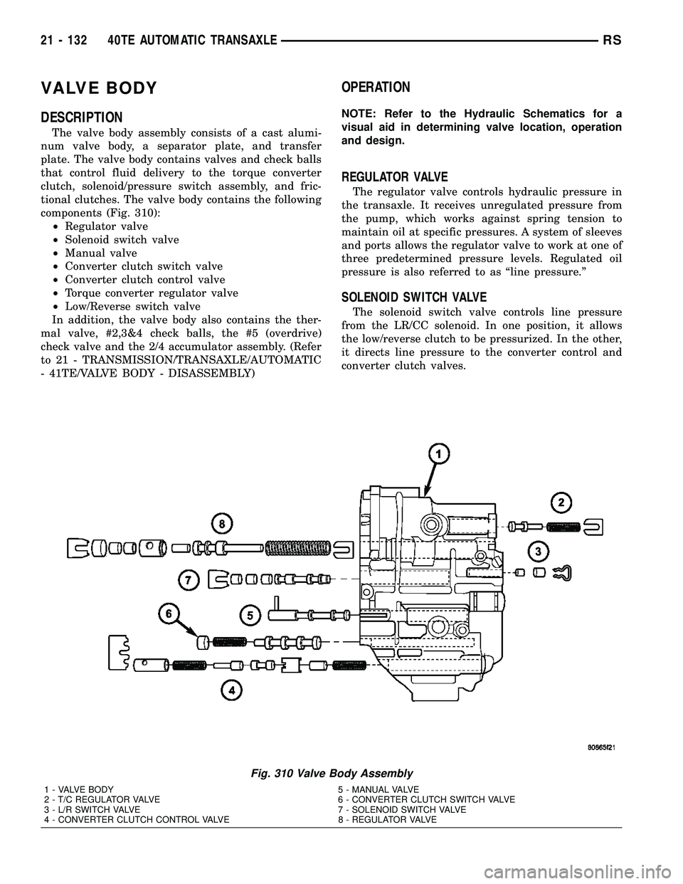
tional clutches. The valve body contains the following
components (Fig. 310):
²Regulator valve
²Solenoid switch valve
²Manual valve
²Converter clutch switch valve
²Converter clutch control valve
²Torque converter regulator valve
²Low/Reverse switch valve
In addition, the valve body also contains the ther-
mal valve, #2,3&4 check balls, the #5 (overdrive)
check valve and the 2/4 accumulator assembly. (Refer
to 21 - TRANSMISSION/TRANSAXLE/AUTOMATIC
- 41TE/VALVE BODY - DISASSEMBLY)
OPERATION
NOTE: Refer to the Hydraulic Schematics for a
visual aid in determining valve location, operation
and design.
REGULATOR VALVE
The regulator valve controls hydraulic pressure in
the transaxle. It receives unregulated pressure from
the pump, which works against spring tension to
maintain oil at specific pressures. A system of sleeves
and ports allows the regulator valve to work at one of
three predetermined pressure levels. Regulated oil
pressure is also referred to as ªline pressure.º
SOLENOID SWITCH VALVE
The solenoid switch valve controls line pressure
from the LR/CC solenoid. In one position, it allows
the low/reverse clutch to be pressurized. In the other,
it directs line pressure to the converter control and
converter clutch valves.
Fig. 310 Valve Body Assembly
1 - VALVE BODY 5 - MANUAL VALVE
2 - T/C REGULATOR VALVE 6 - CONVERTER CLUTCH SWITCH VALVE
3 - L/R SWITCH VALVE 7 - SOLENOID SWITCH VALVE
4 - CONVERTER CLUTCH CONTROL VALVE 8 - REGULATOR VALVE
21 - 132 40TE AUTOMATIC TRANSAXLERS
Page 1594 of 2339
MANUAL VALVE
The manual valve is operated by the mechanical
shift linkage. Its primary responsibility is to send
line pressure to the appropriate hydraulic circuits
and solenoids. The valve has three operating ranges
or positions.
CONVERTER CLUTCH SWITCH VALVE
The main responsibility of the converter clutch
switch valve is to control hydraulic pressure applied
to the front (off) side of the converter clutch piston.
Line pressure from the regulator valve is fed to the
torque converter regulator valve, where it passes
through the valve, and is slightly regulated. The
pressure is then directed to the converter clutch
switch valve and to the front side of the converter
clutch piston. This pressure pushes the piston back
and disengages the converter clutch.
CONVERTER CLUTCH CONTROL VALVE
The converter clutch control valve controls the
back (on) side of the torque converter clutch. When
the PCM/TCM energizes or modulates the LR/CC
solenoid to apply the converter clutch piston, both
the converter clutch control valve and the converter
control valve move, allowing pressure to be applied to
the back side of the clutch.
T/C REGULATOR VALVE
The torque converter regulator valve slightly regu-
lates the flow of fluid to the torque converter.
LOW/REVERSE SWITCH VALVE
The low/reverse clutch is applied from different
sources, depending on whether low (1st) gear or
reverse is selected. The low/reverse switch valve
alternates positions depending on from which direc-
tion fluid pressure is applied. By design, when the
valve is shifted by fluid pressure from one channel,
the opposing channel is blocked. The switch valve
alienates the possibility of a sticking ball check, thus
providing consistent application of the low/reverse
clutch under all operating conditions.
REMOVAL
NOTE: If valve body is replaced or reconditioned,
the ªQuick-Learnº Procedure must be performed.
(Refer to 8 - ELECTRICAL/ELECTRONIC CONTROL
MODULES/TRANSMISSION CONTROL MODULE -
STANDARD PROCEDURE)
(1) Disconnect battery negative cable.
(2) Disconnect gearshift cable from manual valve
lever.
(3) Remove manual valve lever from manual shaft.
(4) Raise vehicle on hoist.
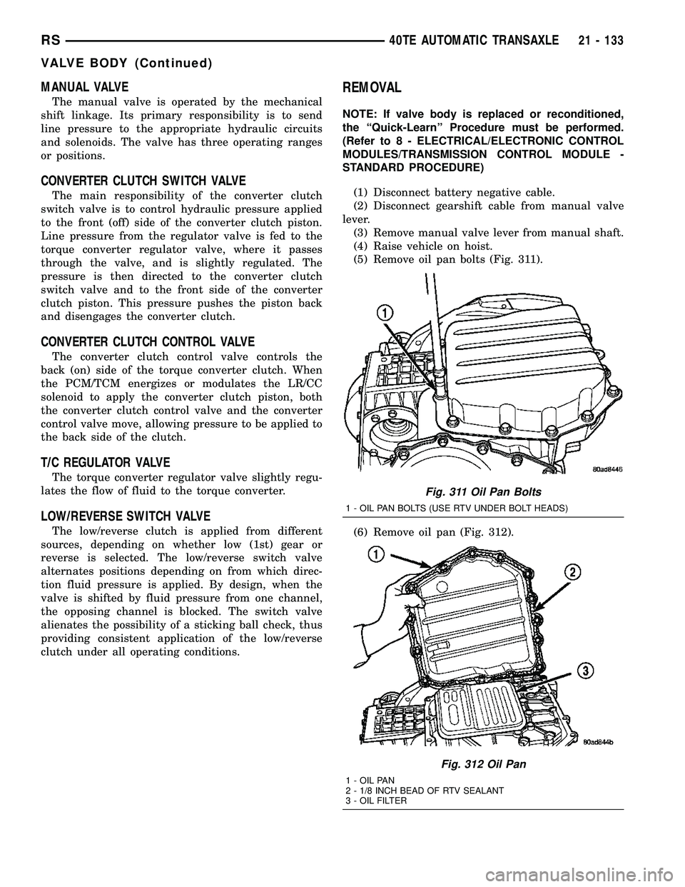
(5) Remove oil pan bolts (Fig. 311).
(6) Remove oil pan (Fig. 312).
Fig. 311 Oil Pan Bolts
1 - OIL PAN BOLTS (USE RTV UNDER BOLT HEADS)
Fig. 312 Oil Pan
1 - OIL PAN
2 - 1/8 INCH BEAD OF RTV SEALANT
3 - OIL FILTER
RS40TE AUTOMATIC TRANSAXLE21 - 133
VALVE BODY (Continued)
Page 1607 of 2339
41TE AUTOMATIC TRANSAXLE
TABLE OF CONTENTS
page page
41TE AUTOMATIC TRANSAXLE
DESCRIPTION........................147
OPERATION..........................149
DIAGNOSIS AND TESTING
DIAGNOSIS AND TESTING - 4XTE
TRANSAXLE GENERAL DIAGNOSIS......149
DIAGNOSIS AND TESTING - ROAD TEST . . 150
DIAGNOSIS AND TESTING - HYDRAULIC
PRESSURE TESTS...................150
DIAGNOSIS AND TESTING - CLUTCH AIR
PRESSURE TESTS...................153
DIAGNOSIS AND TESTING - TORQUE
CONVERTER HOUSING FLUID LEAKAGE . . 154
REMOVAL............................154
DISASSEMBLY........................157
ASSEMBLY...........................174
INSTALLATION........................196
SCHEMATICS AND DIAGRAMS
4XTE TRANSAXLE HYDRAULIC
SCHEMATICS.......................199
SPECIFICATIONS - 41TE TRANSAXLE......211
SPECIAL TOOLS
41TE AUTOMATIC TRANSAXLE.........213
ACCUMULATOR
DESCRIPTION........................218
OPERATION..........................218
DRIVING CLUTCHES
DESCRIPTION........................219
OPERATION..........................219
FINAL DRIVE
DESCRIPTION........................219
OPERATION..........................220
DISASSEMBLY........................220
ASSEMBLY...........................224
ADJUSTMENTS
ADJUSTMENT - DIFFERENTIAL BEARING
PRELOAD..........................228
FLUID
STANDARD PROCEDURE
FLUID LEVEL AND CONDITION CHECK . . . 230
STANDARD PROCEDURE - FLUID AND
FILTER SERVICE.....................231
GEAR SHIFT CABLE
REMOVAL............................233
INSTALLATION........................234
ADJUSTMENTS
GEARSHIFT CABLE ADJUSTMENT.......235
HOLDING CLUTCHES
DESCRIPTION........................236
OPERATION..........................236INPUT CLUTCH ASSEMBLY
DISASSEMBLY........................237
ASSEMBLY...........................246
OIL PUMP
DESCRIPTION........................261
OPERATION..........................261
DISASSEMBLY........................261
ASSEMBLY...........................263
PLANETARY GEARTRAIN
DESCRIPTION........................263
OPERATION..........................263
SEAL - OIL PUMP
REMOVAL............................264
INSTALLATION........................264
SHIFT INTERLOCK SOLENOID
DESCRIPTION........................264
OPERATION..........................265
DIAGNOSIS AND TESTING - BRAKE/
TRANSMISSION SHIFT INTERLOCK
SOLENOID..........................266
REMOVAL............................266
INSTALLATION........................267
SOLENOID/PRESSURE SWITCH ASSY
DESCRIPTION........................268
OPERATION..........................268
REMOVAL............................269
INSTALLATION........................270
SPEED SENSOR - INPUT
DESCRIPTION........................271
OPERATION..........................271
REMOVAL............................272
INSTALLATION........................272
SPEED SENSOR - OUTPUT
DESCRIPTION........................273
OPERATION..........................273
REMOVAL............................274
INSTALLATION........................274
TORQUE CONVERTER
DESCRIPTION........................275
OPERATION..........................278
REMOVAL............................280
INSTALLATION........................280
TRANSMISSION CONTROL RELAY
DESCRIPTION........................281
OPERATION..........................281
TRANSMISSION RANGE SENSOR
DESCRIPTION........................281
OPERATION..........................282
REMOVAL............................282
INSTALLATION........................282
21 - 146 41TE AUTOMATIC TRANSAXLERS
Page 1610 of 2339
TRANSAXLE IDENTIFICATION
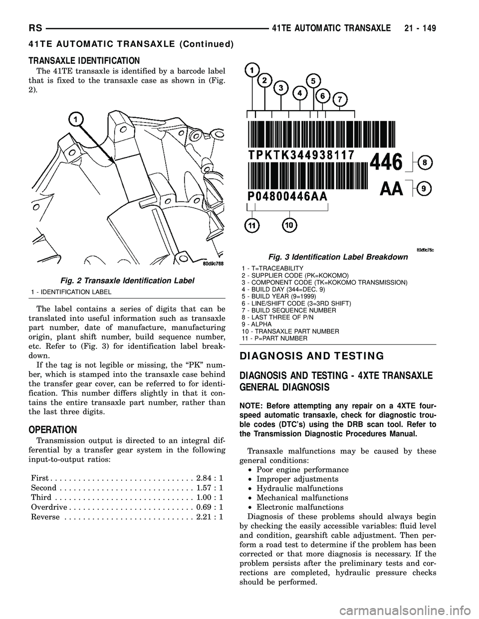
The 41TE transaxle is identified by a barcode label
that is fixed to the transaxle case as shown in (Fig.
2).
The label contains a series of digits that can be
translated into useful information such as transaxle
part number, date of manufacture, manufacturing
origin, plant shift number, build sequence number,
etc. Refer to (Fig. 3) for identification label break-
down.
If the tag is not legible or missing, the ªPKº num-
ber, which is stamped into the transaxle case behind
the transfer gear cover, can be referred to for identi-
fication. This number differs slightly in that it con-
tains the entire transaxle part number, rather than
the last three digits.
OPERATION
Transmission output is directed to an integral dif-
ferential by a transfer gear system in the following
input-to-output ratios:
First...............................2.84 : 1
Second.............................1.57 : 1
Third..............................1.00 : 1
Overdrive...........................0.69 : 1
Reverse............................2.21 : 1
DIAGNOSIS AND TESTING
DIAGNOSIS AND TESTING - 4XTE TRANSAXLE
GENERAL DIAGNOSIS
NOTE: Before attempting any repair on a 4XTE four-
speed automatic transaxle, check for diagnostic trou-
ble codes (DTC's) using the DRB scan tool. Refer to
the Transmission Diagnostic Procedures Manual.
Transaxle malfunctions may be caused by these
general conditions:
²Poor engine performance
²Improper adjustments
²Hydraulic malfunctions
²Mechanical malfunctions
²Electronic malfunctions
Diagnosis of these problems should always begin
by checking the easily accessible variables: fluid level
and condition, gearshift cable adjustment. Then per-
form a road test to determine if the problem has been
corrected or that more diagnosis is necessary. If the
problem persists after the preliminary tests and cor-
rections are completed, hydraulic pressure checks
should be performed.
Fig. 2 Transaxle Identification Label
1 - IDENTIFICATION LABEL
Fig. 3 Identification Label Breakdown
1 - T=TRACEABILITY
2 - SUPPLIER CODE (PK=KOKOMO)
3 - COMPONENT CODE (TK=KOKOMO TRANSMISSION)
4 - BUILD DAY (344=DEC. 9)
5 - BUILD YEAR (9=1999)
6 - LINE/SHIFT CODE (3=3RD SHIFT)
7 - BUILD SEQUENCE NUMBER
8 - LAST THREE OF P/N
9 - ALPHA
10 - TRANSAXLE PART NUMBER
11 - P=PART NUMBER
RS41TE AUTOMATIC TRANSAXLE21 - 149
41TE AUTOMATIC TRANSAXLE (Continued)
Page 1691 of 2339
CAUTION: Do not damage the transaxle case and/or
differential retainer sealing surface.
(9) Using the end play measurement that was
determined, add 0.18mm (0.007 inch). This should
give you between 5-18 inch pounds of bearing pre-
load. Refer to the Differential Bearing Shim Chart to
determine which shim to use.
(10) Remove the differential bearing retainer.
Remove the bearing cup.
(11) Install the oil baffle. Install the proper shim
combination under the bearing cup.
(12) Install the differential bearing retainer. Seal
the retainer to the housing with MopartSilicone
Rubber Adhesive Sealant. Torque bolts to 28 N´m
(250 in. lbs.).
(13) Using Miller Special Tool L-4436-A and an
inch-pound torque wrench, check the turning torque
of the differential (Fig. 204). The turning torque
should be between 5-18 inch-pounds.
NOTE: If turning torque is too high install a 0.05mm
(0.002 inch) thicker shim. If the turning torque is too
low, install a 0.05mm (0.002 inch) thinner shim.
Repeat until 5-18 inch-pounds of turning torque is
obtained.
FLUID
STANDARD PROCEDURE
FLUID LEVEL AND CONDITION CHECK
NOTE: Only transmission fluid of the type labeled
Mopar ATF+4 (Automatic Transmission Fluid)
should be used in this transaxle.
FLUID LEVEL CHECK
The transmission sump has a fluid level indicator
(dipstick) to check oil similar to most automatic
transmissions. It is located on the left side of the
engine. Be sure to wipe all dirt from dipstick handle
before removing.
The torque converter fills in both the P Park and N
Neutral positions. Place the selector lever in P Park
to be sure that the fluid level check is accurate.The
engine should be running at idle speed for at
least one minute, with the vehicle on level
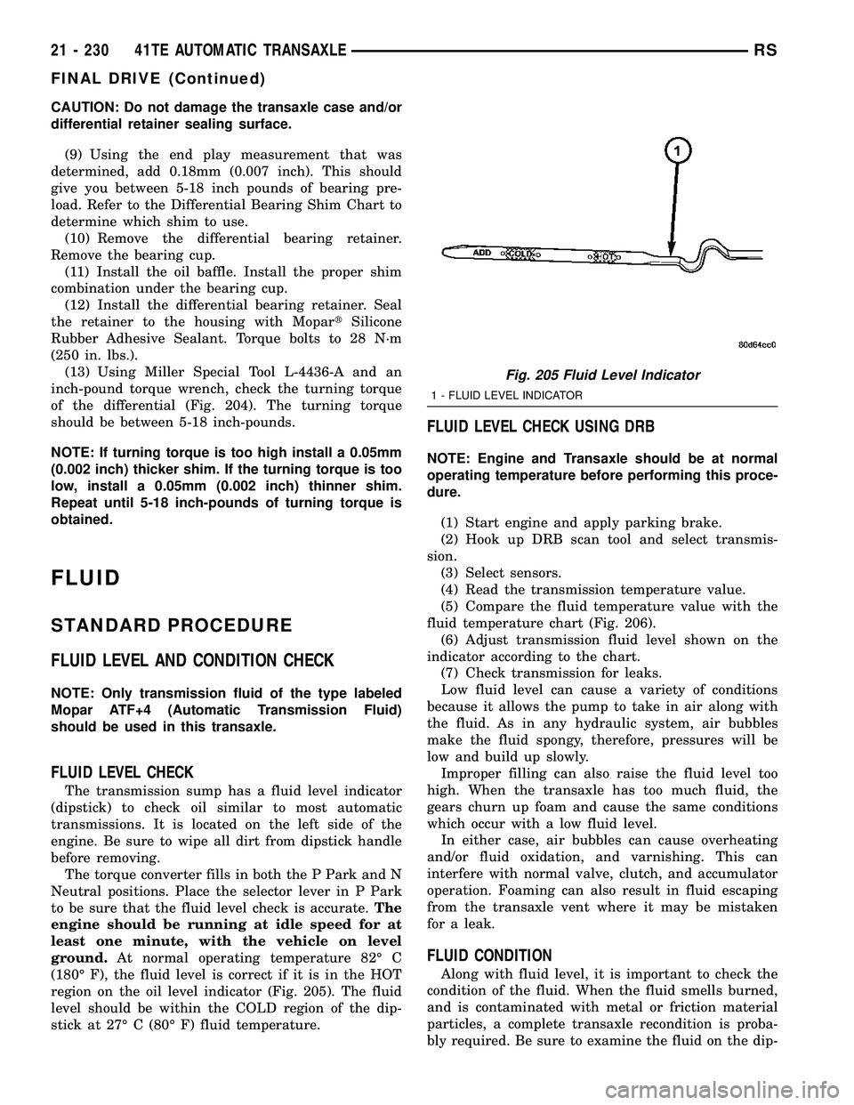
ground.At normal operating temperature 82É C
(180É F), the fluid level is correct if it is in the HOT
region on the oil level indicator (Fig. 205). The fluid
level should be within the COLD region of the dip-
stick at 27É C (80É F) fluid temperature.
FLUID LEVEL CHECK USING DRB
NOTE: Engine and Transaxle should be at normal
operating temperature before performing this proce-
dure.
(1) Start engine and apply parking brake.
(2) Hook up DRB scan tool and select transmis-
sion.
(3) Select sensors.
(4) Read the transmission temperature value.
(5) Compare the fluid temperature value with the
fluid temperature chart (Fig. 206).
(6) Adjust transmission fluid level shown on the
indicator according to the chart.
(7) Check transmission for leaks.
Low fluid level can cause a variety of conditions
because it allows the pump to take in air along with
the fluid. As in any hydraulic system, air bubbles
make the fluid spongy, therefore, pressures will be
low and build up slowly.
Improper filling can also raise the fluid level too
high. When the transaxle has too much fluid, the
gears churn up foam and cause the same conditions
which occur with a low fluid level.
In either case, air bubbles can cause overheating
and/or fluid oxidation, and varnishing. This can
interfere with normal valve, clutch, and accumulator
operation. Foaming can also result in fluid escaping
from the transaxle vent where it may be mistaken
for a leak.
FLUID CONDITION
Along with fluid level, it is important to check the
condition of the fluid. When the fluid smells burned,
and is contaminated with metal or friction material
particles, a complete transaxle recondition is proba-
bly required. Be sure to examine the fluid on the dip-
Fig. 205 Fluid Level Indicator
1 - FLUID LEVEL INDICATOR
21 - 230 41TE AUTOMATIC TRANSAXLERS
FINAL DRIVE (Continued)