Page 1449 of 2339
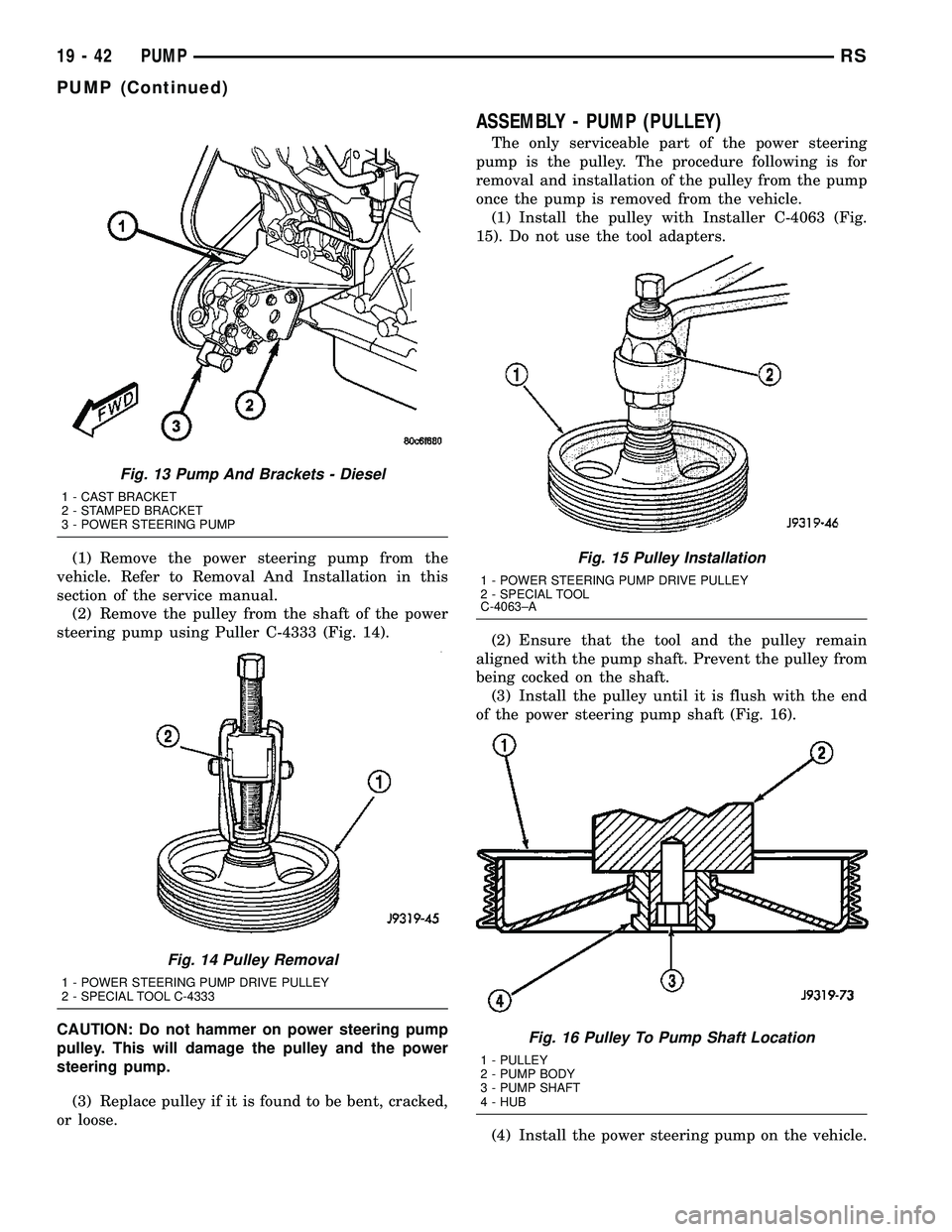
(1) Remove the power steering pump from the
vehicle. Refer to Removal And Installation in this
section of the service manual.
(2) Remove the pulley from the shaft of the power
steering pump using Puller C-4333 (Fig. 14).
CAUTION: Do not hammer on power steering pump
pulley. This will damage the pulley and the power
steering pump.
(3) Replace pulley if it is found to be bent, cracked,
or loose.
ASSEMBLY - PUMP (PULLEY)
The only serviceable part of the power steering
pump is the pulley. The procedure following is for
removal and installation of the pulley from the pump
once the pump is removed from the vehicle.
(1) Install the pulley with Installer C-4063 (Fig.
15). Do not use the tool adapters.
(2) Ensure that the tool and the pulley remain
aligned with the pump shaft. Prevent the pulley from
being cocked on the shaft.
(3) Install the pulley until it is flush with the end
of the power steering pump shaft (Fig. 16).
(4) Install the power steering pump on the vehicle.
Fig. 13 Pump And Brackets - Diesel
1 - CAST BRACKET
2 - STAMPED BRACKET
3 - POWER STEERING PUMP
Fig. 14 Pulley Removal
1 - POWER STEERING PUMP DRIVE PULLEY
2 - SPECIAL TOOL C-4333
Fig. 15 Pulley Installation
1 - POWER STEERING PUMP DRIVE PULLEY
2 - SPECIAL TOOL
C-4063±A
Fig. 16 Pulley To Pump Shaft Location
1 - PULLEY
2 - PUMP BODY
3 - PUMP SHAFT
4 - HUB
19 - 42 PUMPRS
PUMP (Continued)
Page 1462 of 2339
TRANSMISSION/TRANSAXLE
TABLE OF CONTENTS
page page
40TE AUTOMATIC TRANSAXLE..............141TE AUTOMATIC TRANSAXLE............146
40TE AUTOMATIC TRANSAXLE
TABLE OF CONTENTS
page page
40TE AUTOMATIC TRANSAXLE
DESCRIPTION..........................2
OPERATION............................4
DIAGNOSIS AND TESTING
DIAGNOSIS AND TESTING - 4XTE
TRANSAXLE GENERAL DIAGNOSIS........5
DIAGNOSIS AND TESTING - ROAD TEST....5
DIAGNOSIS AND TESTING - HYDRAULIC
PRESSURE TESTS.....................6
DIAGNOSIS AND TESTING - CLUTCH AIR
PRESSURE TESTS.....................8
DIAGNOSIS AND TESTING - TORQUE
CONVERTER HOUSING FLUID LEAKAGE....9
REMOVAL.............................9
DISASSEMBLY.........................12
ASSEMBLY............................29
INSTALLATION.........................51
SCHEMATICS AND DIAGRAMS
4XTE TRANSAXLE HYDRAULIC
SCHEMATICS........................54
SPECIFICATIONS - 41TE TRANSAXLE.......66
SPECIAL TOOLS.......................68
ACCUMULATOR
DESCRIPTION.........................73
OPERATION...........................73
DRIVING CLUTCHES
DESCRIPTION.........................74
OPERATION...........................74
FINAL DRIVE
DESCRIPTION.........................74
OPERATION...........................75
DISASSEMBLY.........................75
ASSEMBLY............................78
ADJUSTMENTS
DIFFERENTIAL BEARING PRELOAD
MEASUREMENT AND ADJUSTMENT......79FLUID
STANDARD PROCEDURE
FLUID LEVEL AND CONDITION CHECK....82
STANDARD PROCEDURE - FLUID AND
FILTER SERVICE......................82
GEAR SHIFT CABLE
REMOVAL.............................84
HOLDING CLUTCHES
DESCRIPTION.........................86
OPERATION...........................86
INPUT CLUTCH ASSEMBLY
DISASSEMBLY.........................86
ASSEMBLY............................95
OIL PUMP
DESCRIPTION........................110
OPERATION..........................110
DISASSEMBLY........................110
ASSEMBLY...........................112
PLANETARY GEARTRAIN
DESCRIPTION........................112
OPERATION..........................112
SEAL - OIL PUMP
REMOVAL............................113
INSTALLATION........................113
SHIFT INTERLOCK SOLENOID
DESCRIPTION........................113
OPERATION..........................114
DIAGNOSIS AND TESTING - BRAKE/
TRANSMISSION SHIFT INTERLOCK
SOLENOID..........................115
REMOVAL............................115
INSTALLATION........................116
SOLENOID/PRESSURE SWITCH ASSY
DESCRIPTION........................117
OPERATION..........................118
REMOVAL............................118
INSTALLATION........................119
RSTRANSMISSION/TRANSAXLE21-1
Page 1480 of 2339
NOTE: The 2/4 Clutch Piston has bonded seals
which are not individually serviceable. Seal replace-
ment requires replacement of the piston assembly.
(27) Remove 2/4 clutch retainer (Fig. 42).
(28) Remove 2/4 clutch return spring (Fig. 43).(29) Remove 2/4 clutch pack (Fig. 44).Tag 2/4
clutch pack for reassembly identification.
(30) Remove tapered snap ring (Fig. 45).
Fig. 42 2/4 Clutch Retainer
1 - 2/4 CLUTCH RETAINER
2 - 2/4 CLUTCH RETURN SPRING
Fig. 43 Remove 2/4 Clutch Return Spring
1 - 2/4 CLUTCH RETURN SPRING
Fig. 44 Remove 2/4 Clutch Pack
1 - CLUTCH DISC
2 - CLUTCH PLATE
Fig. 45 Remove Tapered Snap Ring
1 - LOW/REVERSE CLUTCH REACTION PLATE
2 - SCREWDRIVER
3 - LOW/REVERSE TAPERED SNAP RING (TAPERED SIDE UP)
4 - OIL PAN FACE
5 - LONG TAB
RS40TE AUTOMATIC TRANSAXLE21-19
40TE AUTOMATIC TRANSAXLE (Continued)
Page 1489 of 2339
NOTE: The Low/Reverse Clutch Piston has bonded
seals which are not individually serviceable. Seal
replacement requires replacement of the piston
assembly.
(62) Remove low/reverse clutch piston (Fig. 79).
(63) Remove low/reverse piston retainer-to-case
screws (Fig. 80).(64) Remove low/reverse piston retainer (Fig. 81).
(65) Remove low/reverse piston retainer-to-case
gasket (Fig. 82).
Fig. 79 Remove Low/Reverse Clutch Piston
1 - LOW/REVERSE CLUTCH PISTON
2 - BONDED SEAL
3 - BONDED SEAL
Fig. 80 Remove Piston Retainer-to-Case Screws
1 - LOW/REVERSE CLUTCH PISTON RETAINER
2 - SCREWDRIVER
3 - TORX-LOC SCREWS
Fig. 81 Remove Piston Retainer
1 - LOW/REVERSE CLUTCH PISTON RETAINER
2 - GASKET
Fig. 82 Remove Piston Retainer Gasket
1 - GASKET HOLES MUST LINE UP
2 - LOW/REVERSE CLUTCH PISTON RETAINER GASKET
21 - 28 40TE AUTOMATIC TRANSAXLERS
40TE AUTOMATIC TRANSAXLE (Continued)
Page 1491 of 2339
(3) Install low/reverse piston retainer (Fig. 87).
(4) Install low/reverse piston retainer-to-case bolts
(Fig. 88) and torque to 5 N´m (45 in. lbs.).
NOTE: The Low/Reverse Clutch Piston has bonded
seals which are not individually serviceable. Seal
replacement requires replacement of the piston
assembly.(5) Install low/reverse clutch piston (Fig. 89).
(6) Assemble park guide bracket assembly (Fig.
91) (Fig. 90).
Fig. 87 Install Piston Retainer
1 - LOW/REVERSE CLUTCH PISTON RETAINER
2 - GASKET
Fig. 88 Install Piston Retainer-to-Case Screws
1 - LOW/REVERSE CLUTCH PISTON RETAINER
2 - SCREWDRIVER
3 - TORX-LOC SCREWS
Fig. 89 Install Low/Reverse Clutch Piston
1 - LOW/REVERSE CLUTCH PISTON
2 - BONDED SEAL
3 - BONDED SEAL
Fig. 90 Guide Bracket Disassembled
1 - ANTIRATCHET SPRING
2 - GUIDE BRACKET
3 - SPLIT SLEEVE
4 - SPACER
5-PAWL
6 - STEPPED SPACER
21 - 30 40TE AUTOMATIC TRANSAXLERS
40TE AUTOMATIC TRANSAXLE (Continued)
Page 1505 of 2339
NOTE: The 2/4 Clutch Piston has bonded seals
which are not individually serviceable. Seal replace-
ment requires replacement of the piston assembly.
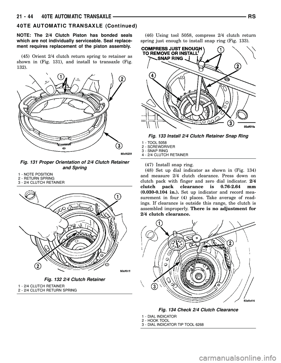
(45) Orient 2/4 clutch return spring to retainer as
shown in (Fig. 131), and install to transaxle (Fig.
132).(46) Using tool 5058, compress 2/4 clutch return
spring just enough to install snap ring (Fig. 133).
(47) Install snap ring.
(48) Set up dial indicator as shown in (Fig. 134)
and measure 2/4 clutch clearance. Press down on
clutch pack with finger and zero dial indicator.2/4
clutch pack clearance is 0.76-2.64 mm
(0.030-0.104 in.).Set up indicator and record mea-
surement in four (4) places. Take average of read-
ings. If clearance is outside this range, the clutch is
assembled improperly.There is no adjustment for
2/4 clutch clearance.
Fig. 131 Proper Orientation of 2/4 Clutch Retainer
and Spring
1 - NOTE POSITION
2 - RETURN SPRING
3 - 2/4 CLUTCH RETAINER
Fig. 132 2/4 Clutch Retainer
1 - 2/4 CLUTCH RETAINER
2 - 2/4 CLUTCH RETURN SPRING
Fig. 133 Install 2/4 Clutch Retainer Snap Ring
1 - TOOL 5058
2 - SCREWDRIVER
3 - SNAP RING
4 - 2/4 CLUTCH RETAINER
Fig. 134 Check 2/4 Clutch Clearance
1 - DIAL INDICATOR
2 - HOOK TOOL
3 - DIAL INDICATOR TIP TOOL 6268
21 - 44 40TE AUTOMATIC TRANSAXLERS
40TE AUTOMATIC TRANSAXLE (Continued)
Page 1536 of 2339
OPERATION
The differential assembly is driven by the transfer
shaft by way of the differential ring gear. The ring
gear drives the differential case, and the case drives
the driveshafts through the differential gears. The
differential pinion and side gears are supported in
the case by thrust washers and a pinion shaft. Dif-
ferential pinion and side gears make it possible for
front tires to rotate at different speeds while corner-
ing.
DISASSEMBLY
NOTE: The differential is serviced as an assembly.
The only parts that are serviceable within the differ-
ential are the differential bearing cups and cones. If
any other part fails within the differential, you must
replace the differential assembly along with the
transfer shaft.
The transfer shaft should be removed for differen-
tial repair and bearing turning torque checking.
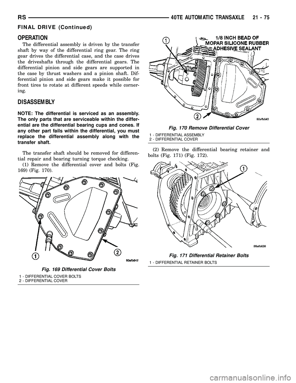
(1) Remove the differential cover and bolts (Fig.
169) (Fig. 170).(2) Remove the differential bearing retainer and
bolts (Fig. 171) (Fig. 172).
Fig. 169 Differential Cover Bolts
1 - DIFFERENTIAL COVER BOLTS
2 - DIFFERENTIAL COVER
Fig. 170 Remove Differential Cover
1 - DIFFERENTIAL ASSEMBLY
2 - DIFFERENTIAL COVER
Fig. 171 Differential Retainer Bolts
1 - DIFFERENTIAL RETAINER BOLTS
RS40TE AUTOMATIC TRANSAXLE21-75
FINAL DRIVE (Continued)
Page 1539 of 2339
DIFFERENTIAL SERVICE TOOLS
COMPONENT REMOVER INSTALLER
Diff. Bear. On
Retainer Side5048, 5048-4
Collets,
L-4539-2
Button5052, C-4171
Diff. Bear. On
Ext. Hous. Side5048, 5048-3
Collets,
L-4539-2
ButtonL-4410, C-4171
Diff. Race. On
Retainer Side6062-A 6061, C-4171
Diff. Race. On
Ext. Hous. SideL-4518 L-4520, C-4171
Extension
Housing Seal7794-A, C-637
Slide HammerL-4520, C-4171
Bearing
Retainer Seal794-A, C-637
Slide HammerL-4520, C-4171
ASSEMBLY
NOTE: The differential is serviced as an assembly.
The only parts that are serviceable within the differ-
ential are the differential bearing cups and cones. If
any other part fails within the differential, you must
replace the differential assembly along with the
transfer shaft.
NOTE: Use MoparTATF RTV (MS-GF41), or equiva-
lent, on retainer and extension housing/adapter
plate to seal to case.
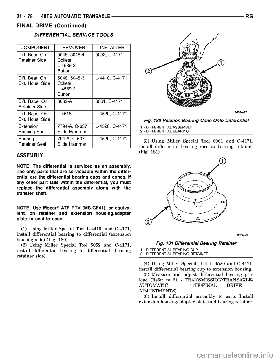
(1) Using Miller Special Tool L-4410, and C-4171,
install differential bearing to differential (extension
housing side) (Fig. 180).
(2) Using Miller Special Tool 5052 and C-4171,
install differential bearing to differential (bearing
retainer side).(3) Using Miller Special Tool 6061 and C-4171,
install differential bearing race to bearing retainer
(Fig. 181).
(4) Using Miller Special Tool L±4520 and C-4171,
install differential bearing cup to extension housing.
(5) Measure and adjust differential bearing pre-
load (Refer to 21 - TRANSMISSION/TRANSAXLE/
AUTOMATIC - 41TE/FINAL DRIVE -
ADJUSTMENTS) .
(6) Install differential assembly to case. Install
extension housing/adapter plate and bearing retainer.
Fig. 180 Position Bearing Cone Onto Differential
1 - DIFFERENTIAL ASSEMBLY
2 - DIFFERENTIAL BEARING
Fig. 181 Differential Bearing Retainer
1 - DIFFERENTIAL BEARING CUP
2 - DIFFERENTIAL BEARING RETAINER
21 - 78 40TE AUTOMATIC TRANSAXLERS
FINAL DRIVE (Continued)