2005 CHRYSLER CARAVAN wiring
[x] Cancel search: wiringPage 2169 of 2339
A/C COMPRESSOR CLUTCH
RELAY
DESCRIPTION
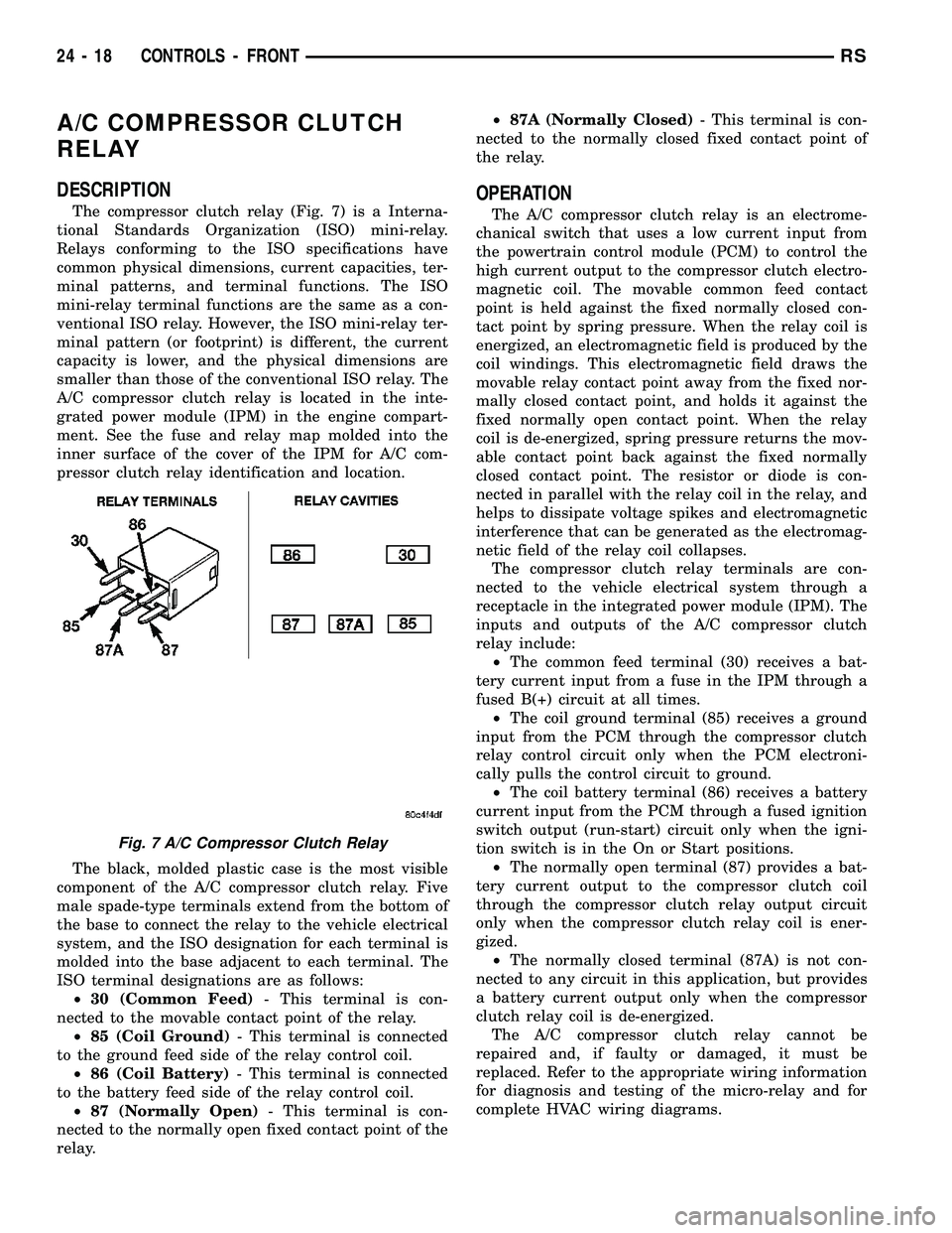
The compressor clutch relay (Fig. 7) is a Interna-
tional Standards Organization (ISO) mini-relay.
Relays conforming to the ISO specifications have
common physical dimensions, current capacities, ter-
minal patterns, and terminal functions. The ISO
mini-relay terminal functions are the same as a con-
ventional ISO relay. However, the ISO mini-relay ter-
minal pattern (or footprint) is different, the current
capacity is lower, and the physical dimensions are
smaller than those of the conventional ISO relay. The
A/C compressor clutch relay is located in the inte-
grated power module (IPM) in the engine compart-
ment. See the fuse and relay map molded into the
inner surface of the cover of the IPM for A/C com-
pressor clutch relay identification and location.
The black, molded plastic case is the most visible
component of the A/C compressor clutch relay. Five
male spade-type terminals extend from the bottom of
the base to connect the relay to the vehicle electrical
system, and the ISO designation for each terminal is
molded into the base adjacent to each terminal. The
ISO terminal designations are as follows:
²30 (Common Feed)- This terminal is con-
nected to the movable contact point of the relay.
²85 (Coil Ground)- This terminal is connected
to the ground feed side of the relay control coil.
²86 (Coil Battery)- This terminal is connected
to the battery feed side of the relay control coil.
²87 (Normally Open)- This terminal is con-
nected to the normally open fixed contact point of the
relay.²87A (Normally Closed)- This terminal is con-
nected to the normally closed fixed contact point of
the relay.
OPERATION
The A/C compressor clutch relay is an electrome-
chanical switch that uses a low current input from
the powertrain control module (PCM) to control the
high current output to the compressor clutch electro-
magnetic coil. The movable common feed contact
point is held against the fixed normally closed con-
tact point by spring pressure. When the relay coil is
energized, an electromagnetic field is produced by the
coil windings. This electromagnetic field draws the
movable relay contact point away from the fixed nor-
mally closed contact point, and holds it against the
fixed normally open contact point. When the relay
coil is de-energized, spring pressure returns the mov-
able contact point back against the fixed normally
closed contact point. The resistor or diode is con-
nected in parallel with the relay coil in the relay, and
helps to dissipate voltage spikes and electromagnetic
interference that can be generated as the electromag-
netic field of the relay coil collapses.
The compressor clutch relay terminals are con-
nected to the vehicle electrical system through a
receptacle in the integrated power module (IPM). The
inputs and outputs of the A/C compressor clutch
relay include:
²The common feed terminal (30) receives a bat-
tery current input from a fuse in the IPM through a
fused B(+) circuit at all times.
²The coil ground terminal (85) receives a ground
input from the PCM through the compressor clutch
relay control circuit only when the PCM electroni-
cally pulls the control circuit to ground.
²The coil battery terminal (86) receives a battery
current input from the PCM through a fused ignition
switch output (run-start) circuit only when the igni-
tion switch is in the On or Start positions.
²The normally open terminal (87) provides a bat-
tery current output to the compressor clutch coil
through the compressor clutch relay output circuit
only when the compressor clutch relay coil is ener-
gized.
²The normally closed terminal (87A) is not con-
nected to any circuit in this application, but provides
a battery current output only when the compressor
clutch relay coil is de-energized.
The A/C compressor clutch relay cannot be
repaired and, if faulty or damaged, it must be
replaced. Refer to the appropriate wiring information
for diagnosis and testing of the micro-relay and for
complete HVAC wiring diagrams.
Fig. 7 A/C Compressor Clutch Relay
24 - 18 CONTROLS - FRONTRS
Page 2175 of 2339

The blower motor relay terminals are connected to
the vehicle electrical system through a receptacle in
the Integrated Power Module (IPM). The inputs and
outputs of the blower motor relay include:
²The common feed terminal (30) receives a bat-
tery current input from the battery through a B(+)
circuit at all times.
²The coil ground terminal (85) receives a ground
input through the front/rear blower motor relay con-
trol circuit only when the FCM electronically pulls
the control circuit to ground.
²The coil battery terminal (86) receives a battery
current input from the battery through a B(+) circuit
at all times.
²The normally open terminal (87) provides a bat-
tery current output to the blower motor resistor
(manual heater-A/C control) or blower power module
(automatic heater-A/C control) through a fuse in the
IPM on the fused front blower motor relay output cir-
cuit only when the blower motor relay coil is ener-
gized.
²The normally closed terminal (87A) is not con-
nected to any circuit in this application, but provides
a battery current output only when the blower motor
relay coil is de-energized.
Refer to the appropriate wiring information for
diagnosis and testing of the micro-relay and for com-
plete HVAC wiring diagrams.
REMOVAL
(1) Disconnect and isolate the negative battery
cable.
(2) Remove the cover from the integrated power
module (IPM) (Fig. 13).
NOTE: Refer to the fuse and relay map on the inner
surface of the cover of the IPM for front blower
motor relay identification and location.
(3) Remove the front blower motor relay from the
IPM
INSTALLATION
NOTE: Refer to the fuse and relay map on the inner
surface of the cover of the integrated power module
(IPM) for front blower motor relay identification and
location.
(1) Position the front blower motor relay to the
proper receptacle in the IPM.
(2) Align the front blower motor relay terminals
with the terminal cavities in the IPM receptacle.
(3) Push down firmly on the front blower motor
relay until the terminals are fully seated in the ter-
minal cavities.
(4) Install the cover onto the IPM.(5) Reconnect the negative battery cable.
BLOWER MOTOR RESISTOR
BLOCK
DESCRIPTION
A blower motor resistor is used on this model when
it is equipped with the manual heater-A/C system.
Models equipped with the optional Automatic Tem-
perature Control (ATC) system use a blower power
module, instead of the blower motor resistor block
(Refer to 24 - HEATING & AIR CONDITIONING/
CONTROLS/POWER MODULE - DESCRIPTION).
The blower motor resistor block is mounted to the
rear of the HVAC housing, directly behind the glove
box opening in the instrument panel. The resistor
block consists of a molded plastic mounting plate
with two integral connector receptacles. Concealed
behind the mounting plate are four coiled resistor
wires contained within a protective stamped steel
cage. The blower motor resistor block is accessed for
service by removing the glove box from the instru-
ment panel.
OPERATION
The blower motor resistor block is connected to the
vehicle electrical system through a dedicated take
out and connector of the instrument panel wire har-
ness. A second connector receptacle receives the pig-
tail wire connector from the blower motor. The
blower motor resistor has multiple resistor wires,
Fig. 13 Front Blower Motor Relay
1 - INTEGRATED POWER MODULE (IPM)
2 - FRONT BLOWER MOTOR RELAY
2 - FRONT CONTROL MODULE (FCM)
24 - 24 CONTROLS - FRONTRS
BLOWER MOTOR RELAY (Continued)
Page 2176 of 2339
each of which will reduce the current flow through
the blower motor to change the blower motor speed.
The blower motor switch in the manual heater-A/C
system directs the ground path for the blower motor
through the correct resistor wire to obtain the
selected speed.
With the blower motor switch in the lowest speed
position, the ground path for the motor is applied
through all of the resistor wires. Each higher speed
selected with the blower motor switch applies the
blower motor ground path through fewer of the resis-
tor wires, increasing the blower motor speed.
The blower motor resistor cannot be adjusted or
repaired and, if faulty or damaged, it must be
replaced.
DIAGNOSIS AND TESTING
FRONT BLOWER MOTOR RESISTOR BLOCK
WARNING: ON VEHICLES EQUIPPED WITH AIR-
BAGS, DISABLE THE AIRBAG SYSTEM BEFORE
ATTEMPTING ANY STEERING WHEEL, STEERING
COLUMN, OR INSTRUMENT PANEL COMPONENT
DIAGNOSIS OR SERVICE. DISCONNECT AND ISO-
LATE THE BATTERY NEGATIVE (GROUND) CABLE,
THEN WAIT TWO MINUTES FOR THE AIRBAG SYS-
TEM CAPACITOR TO DISCHARGE BEFORE PER-
FORMING FURTHER DIAGNOSIS OR SERVICE. THIS
IS THE ONLY SURE WAY TO DISABLE THE AIRBAG
SYSTEM. FAILURE TO TAKE THE PROPER PRE-
CAUTIONS COULD RESULT IN ACCIDENTAL AIR-
BAG DEPLOYMENT AND POSSIBLE PERSONAL
INJURY.
For circuit descriptions and diagrams, refer to the
appropriate wiring information. The wiring informa-
tion includes wiring diagrams, proper wire and con-
nector repair procedures, further details on wire
harness routing and retention, as well as pin-out and
location views for the various wire harness connec-
tors, splices and grounds.
(1) Disconnect and isolate the battery negative
cable.
(2) Remove the glove box from the instrument
panel (Refer to 23 - BODY/INSTRUMENT PANEL/
GLOVE BOX - REMOVAL).
(3) Disconnect the two wire harness connectors
from the blower motor resistor block.
(4) Check for continuity between each of the
blower motor switch input terminals of the resistor
and the resistor output terminal. In each case there
should be continuity. If OK, repair the wire harness
circuits between the blower motor switch and the
blower motor resistor, blower motor or blower motorrelay as required. If not OK, replace the faulty
blower motor resistor block.
REMOVAL
WARNING: ON VEHICLES EQUIPPED WITH AIR-
BAGS, DISABLE THE AIRBAG SYSTEM BEFORE
ATTEMPTING ANY STEERING WHEEL, STEERING
COLUMN, OR INSTRUMENT PANEL COMPONENT
DIAGNOSIS OR SERVICE. DISCONNECT AND ISO-
LATE THE BATTERY NEGATIVE (GROUND) CABLE,
THEN WAIT TWO MINUTES FOR THE AIRBAG SYS-
TEM CAPACITOR TO DISCHARGE BEFORE PER-
FORMING FURTHER DIAGNOSIS OR SERVICE. THIS
IS THE ONLY SURE WAY TO DISABLE THE AIRBAG
SYSTEM. FAILURE TO TAKE THE PROPER PRE-
CAUTIONS COULD RESULT IN ACCIDENTAL AIR-
BAG DEPLOYMENT AND POSSIBLE PERSONAL
INJURY.
WARNING: THE BLOWER MOTOR RESISTOR
BLOCK MAY GET VERY HOT DURING NORMAL
OPERATION. IF THE BLOWER MOTOR WAS
TURNED ON PRIOR TO SERVICING THE BLOWER
MOTOR RESISTOR BLOCK, WAIT FIVE MINUTES
TO ALLOW THE BLOWER MOTOR RESISTORS TO
COOL BEFORE PERFORMING DIAGNOSIS OR SER-
VICE. FAILURE TO TAKE THIS PRECAUTION CAN
RESULT IN PERSONAL INJURY.
CAUTION: Do not operate the blower motor with the
blower motor resistor removed from the circuit.
Failure to take this precaution can result in vehicle
damage.
(1) Disconnect and isolate the battery negative
cable.
(2) Remove the glove box from the instrument
panel (Refer to 23 - BODY/INSTRUMENT PANEL/
GLOVE BOX - REMOVAL).
(3) Disconnect the two wire harness connectors
from the blower motor resistor block (Fig. 14).
(4) Remove the two screws that secure the blower
motor resistor block to the HVAC housing.
(5) Remove the resistor block from the HVAC
housing.
INSTALLATION
(1) Position the blower motor resistor block into
the HVAC housing.
(2) Install the two screws that secure the blower
motor resistor block to the HVAC housing. Tighten
the screws to 2 N´m (17 in. lbs.).
(3) Connect the two wire connectors to the resistor
block.
RSCONTROLS - FRONT24-25
BLOWER MOTOR RESISTOR BLOCK (Continued)
Page 2178 of 2339
The evaporator temperature sensor cannot be
adjusted or repaired and, if faulty or damaged, it
must be replaced.
OPERATION
The evaporator temperature sensor monitors the
temperature of the conditioned air once it passes
through the A/C evaporator. The evaporator temper-
ature sensor will change its internal resistance in
response to the air temperatures it monitors and is
connected to the A/C-heater control through sensor
ground and signal circuits. As the conditioned air
temperature increases, the resistance of the evapora-
tor temperature sensor decreases and the voltage
monitored by the A/C-heater control decreases. The
external location of the evaporator temperature sen-
sor allows the sensor to be removed or installed with-
out disturbing the refrigerant in the A/C system.
The A/C-heater control uses this monitored voltage
reading as an indication of the evaporator tempera-
ture. The A/C-heater control is programmed to
respond to this input by sending electronic messages
to the powertrain control module (PCM) over the con-
troller area network (CAN) data bus. The PCM then
cycles the A/C compressor clutch as necessary to opti-
mize A/C system performance and to protect the A/C
system from evaporator freezing.
The evaporator temperature sensor cannot be
adjusted or repaired and, if faulty or damaged, it
must be replaced.
The evaporator temperature sensor is diagnosed
using the DRBIIItscan tool. Refer to Body Diagnos-
tic Procedures.
REMOVAL
RG MODELS
(1) Disconnect and isolate the battery negative
cable.
(2) Remove the air cleaner housing from the right
side of the engine compartment.
(3) Remove the windshield wiper assembly from
the vehicle (Refer to 8 - ELECTRICAL/WIPERS/
WASHERS/WIPER MODULE - REMOVAL).
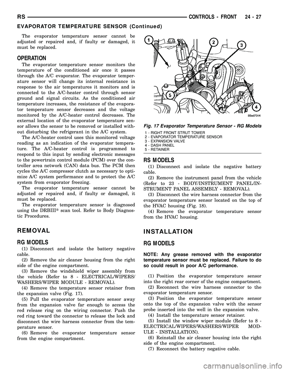
(4) Remove the temperature sensor retainer from
the expansion valve (Fig. 17).
(5) Pull the evaporator temperature sensor away
from the expansion valve far enough to access the
red release ring on the wiring connector. Push the
red ring toward the connector to release the lock and
disconnect the wire harness connector from the tem-
perature sensor.
(6) Remove the evaporator temperature sensor
from the engine compartment.
RS MODELS
(1) Disconnect and isolate the negative battery
cable.
(2) Remove the instrument panel from the vehicle
(Refer to 23 - BODY/INSTRUMENT PANEL/IN-
STRUMENT PANEL ASSEMBLY - REMOVAL).
(3) Disconnect the wire harness connector from the
evaporator temperature sensor located on the top of
the HVAC housing (Fig. 18).
(4) Remove the evaporator temperature sensor
from the HVAC housing.
INSTALLATION
RG MODELS
NOTE: Any grease removed with the evaporator
temperature sensor must be replaced. Failure to do
so could result in poor A/C performance.
(1) Position the evaporator temperature sensor
into the right rear corner of the engine compartment.
(2) Reconnect the wire harness connector to the
evaporator temperature sensor.
(3) Position the evaporator temperature sensor
onto the top of the expansion valve with the sensor
probe inserted into the well in the expansion valve.
(4) Install the temperature sensor retainer.
(5) Install the window wiper module (Refer to 8 -
ELECTRICAL/WIPERS/WASHERS/WIPER MOD-
ULE - INSTALLATION).
(6) Reinstall the air cleaner housing into the right
side of the engine compartment.
(7) Reconnect the battery negative cable.
Fig. 17 Evaporator Temperature Sensor - RG Models
1 - RIGHT FRONT STRUT TOWER
2 - EVAPORATOR TEMPERATURE SENSOR
3 - EXPANSION VALVE
4 - DASH PANEL
5 - RETAINER
RSCONTROLS - FRONT24-27
EVAPORATOR TEMPERATURE SENSOR (Continued)
Page 2188 of 2339
²The normally open terminal (87) provides a bat-
tery current output to the blower motor resistor
(manual heater-A/C control) or blower power module
(ATC heater-A/C control) through a fuse in the IPM
on the fused rear blower motor relay output circuit
only when the blower motor relay coil is energized.
²The normally closed terminal (87A) is not con-
nected to any circuit in this application, but provides
a battery current output only when the rear blower
motor relay coil is de-energized.
Refer to the appropriate wiring information for
diagnosis and testing of the micro-relay and for com-
plete HVAC wiring diagrams.
REMOVAL
(1) Disconnect and isolate the negative battery
cable.
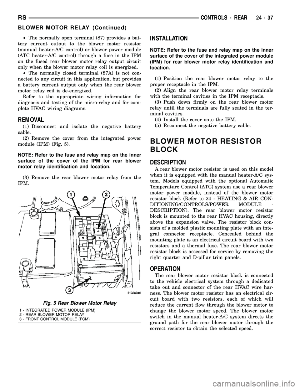
(2) Remove the cover from the integrated power
module (IPM) (Fig. 5).
NOTE: Refer to the fuse and relay map on the inner
surface of the cover of the IPM for rear blower
motor relay identification and location.
(3) Remove the rear blower motor relay from the
IPM.
INSTALLATION
NOTE: Refer to the fuse and relay map on the inner
surface of the cover of the integrated power module
(IPM) for rear blower motor relay identification and
location.
(1) Position the rear blower motor relay to the
proper receptacle in the IPM.
(2) Align the rear blower motor relay terminals
with the terminal cavities in the IPM receptacle.
(3) Push down firmly on the rear blower motor
relay until the terminals are fully seated in the ter-
minal cavities.
(4) Install the cover onto the IPM.
(5) Reconnect the negative battery cable.
BLOWER MOTOR RESISTOR
BLOCK
DESCRIPTION
A rear blower motor resistor is used on this model
when it is equipped with the manual heater-A/C sys-
tem. Models equipped with the optional Automatic
Temperature Control (ATC) system use a rear blower
motor power module, instead of the blower motor
resistor block (Refer to 24 - HEATING & AIR CON-
DITIONING/CONTROLS/POWER MODULE -
DESCRIPTION). The rear blower motor resistor
block is mounted to the rear HVAC housing, directly
above the expansion valve. The resistor block con-
sists of a molded plastic mounting plate with an inte-
gral connector receptacle. Concealed behind the
mounting plate is an electrical circuit board with two
resistors and a thermal fuse. The rear blower motor
resistor block is accessed for service by removing the
right quarter and D-pillar trim panels.
OPERATION
The rear blower motor resistor block is connected
to the vehicle electrical system through a dedicated
take out and connector of the rear HVAC wire har-
ness. The blower motor resistor has an electrical cir-
cuit board with two resistors, each of which will
reduce the current flow through the blower motor to
change the blower motor speed. The blower motor
switch in the manual heater-A/C system directs the
ground path for the rear blower motor through the
correct resistor to obtain the selected speed.
Fig. 5 Rear Blower Motor Relay
1 - INTEGRATED POWER MODULE (IPM)
2 - REAR BLOWER MOTOR RELAY
3 - FRONT CONTROL MODULE (FCM)
RSCONTROLS - REAR24-37
BLOWER MOTOR RELAY (Continued)
Page 2189 of 2339
With the blower motor switch in the lowest speed
position, the ground path for the motor is applied
through both resistors. Each higher speed selected
with the blower motor switch applies the blower
motor ground path through fewer of the resistors,
increasing the blower motor speed. When the blower
motor switch is in the highest speed position, the
blower motor resistors are bypassed and the blower
motor receives a direct path to ground through the
blower motor switch.
The rear blower motor resistor block cannot be
adjusted or repaired and, if faulty or damaged, it
must be replaced.
DIAGNOSIS AND TESTING
REAR BLOWER MOTOR RESISTOR BLOCK
For circuit descriptions and diagrams, refer to the
appropriate wiring information. The wiring informa-
tion includes wiring diagrams, proper wire and con-
nector repair procedures, further details on wire
harness routing and retention, as well as pin-out and
location views for the various wire harness connec-
tors, splices and grounds.
(1) Disconnect and isolate the battery negative
cable.
(2) Disconnect the rear HVAC wire harness con-
nector from the rear blower motor resistor.
(3) Check for continuity between each of the
blower motor switch input terminals of the blower
motor resistor and the resistor output terminal. In
each case there should be continuity. If OK, repair
the wire harness circuits between the blower motor
switch and the blower motor resistor, blower motor or
blower motor relay as required. If not OK, replace
the faulty blower motor resistor block.
REMOVAL
WARNING: THE REAR BLOWER MOTOR RESISTOR
BLOCK MAY GET VERY HOT DURING NORMAL
OPERATION. IF THE BLOWER MOTOR WAS
TURNED ON PRIOR TO SERVICING THE BLOWER
MOTOR RESISTOR BLOCK, WAIT FIVE MINUTES
TO ALLOW THE BLOWER MOTOR RESISTORS TO
COOL BEFORE PERFORMING DIAGNOSIS OR SER-
VICE. FAILURE TO TAKE THIS PRECAUTION CAN
RESULT IN PERSONAL INJURY.CAUTION: Do not operate the blower motor with the
blower motor resistor block removed from the cir-
cuit. Failure to take this precaution can result in
vehicle damage.
(1) Disconnect and isolate the battery negative
cable.
(2) Remove the right quarter trim panel and right
D-pillar trim panel from the quarter inner panel
(Refer to 23 - BODY/INTERIOR/QUARTER TRIM
PANEL - REMOVAL).
(3) Disconnect the rear HVAC wire harness con-
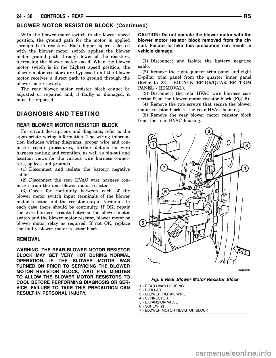
nector from the blower motor resistor block (Fig. 6).
(4) Remove the two screws that secure the blower
motor resistor block to the rear HVAC housing.
(5) Remove the rear blower motor resistor block
from the rear HVAC housing.
Fig. 6 Rear Blower Motor Resistor Block
1 - REAR HVAC HOUSING
2 - D-PILLAR
3 - BLOWER PIGTAIL WIRE
4 - CONNECTOR
5 - EXPANSION VALVE
6 - SCREW (2)
7 - BLOWER MOTOR RESISTOR BLOCK
24 - 38 CONTROLS - REARRS
BLOWER MOTOR RESISTOR BLOCK (Continued)
Page 2197 of 2339
whenever the ignition switch is in the On position
and the A/C-heater control power is turned on.
The blower motor receives battery current when-
ever the front blower motor relay is energized. The
front blower motor relay output circuit is protected
by a fuse in the Integrated Power Module (IPM)
located in the engine compartment near the battery.
In the manual heater-A/C system, the blower motor
speed is controlled by regulating the path to ground
through the blower control switch and the blower
motor resistor. In the ATC system, the blower motor
speed is controlled by an electronic blower motor
power module, which uses a pulse width modulated
input from the ATC module and feedback from the
blower motor to regulate the blower motor ground
path it provides. The blower motor and wheel are
used to control the velocity of air moving through the
HVAC housing by spinning the blower wheel within
the housing at the selected speed or, in the ATC sys-
tem, at the selected or programmed speed.
DIAGNOSIS AND TESTING
FRONT BLOWER MOTOR
BLOWER MOTOR INOPERATIVE
WARNING: ON VEHICLES EQUIPPED WITH AIR-
BAGS, DISABLE THE AIRBAG SYSTEM BEFORE
ATTEMPTING ANY STEERING WHEEL, STEERING
COLUMN, OR INSTRUMENT PANEL COMPONENT
DIAGNOSIS OR SERVICE. DISCONNECT AND ISO-
LATE THE BATTERY NEGATIVE (GROUND) CABLE,
THEN WAIT TWO MINUTES FOR THE AIRBAG SYS-
TEM CAPACITOR TO DISCHARGE BEFORE PER-
FORMING FURTHER DIAGNOSIS OR SERVICE. THIS
IS THE ONLY SURE WAY TO DISABLE THE AIRBAG
SYSTEM. FAILURE TO TAKE THE PROPER PRE-
CAUTIONS COULD RESULT IN ACCIDENTAL AIR-
BAG DEPLOYMENT AND POSSIBLE PERSONAL
INJURY.
For circuit descriptions and diagrams, refer to the
appropriate wiring information. The wiring informa-
tion includes wiring, diagrams, proper wire and con-
nector repair procedures, further details on wire
harness routing and retention, as well as pin-out and
location views for the various wire harness connec-
tors, splices and grounds.BLOWER MOTOR ELECTRICAL DIAGNOSIS
(1) Check the fuse (Fuse 10 - 40 ampere) in the
Integrated Power Module (IPM). If OK, go to Step 2.
If not OK, repair the shorted circuit or component as
required and replace the faulty fuse.
(2) Turn the ignition switch to the On position. Be
certain that the A/C-heater control power is turned
on. Check for battery voltage at the fuse (Fuse 10 -
40 ampere) in the IPM. If OK, go to Step 3. If not
OK, check the front blower motor relay.
(3) Turn the ignition switch to the Off position.
Disconnect and isolate the battery negative cable.
Disconnect the front HVAC wire harness connector
for the front blower motor resistor block (Manual
Temperature Control) or the front blower motor
power module (Automatic Temperature Control) from
the resistor or module connector receptacle. Recon-
nect the battery negative cable. Turn the ignition
switch to the On position. Be certain that the A/C-
heater control power is turned on. Check for battery
voltage at the fused front blower motor relay output
circuit cavity of the front HVAC wire harness connec-
tor for the front blower motor resistor block (MTC) or
the front blower motor power module (ATC). If OK,
go to Step 4. If not OK, repair the open fused front
blower motor relay output circuit to the IPM as
required.
(4) Turn the ignition switch to the Off position.
Disconnect and isolate the battery negative cable.
Disconnect the front blower motor pigtail wire con-
nector from the connector receptacle of the front
blower motor resistor block (MTC) or the front
blower motor power module (ATC). Use jumper wires
to connect a battery and ground feeds to the blower
motor pigtail wire connector. The blower motor
should operate. If OK with MTC, proceed to diagno-
sis of the front blower motor resistor block (Refer to
24 - HEATING & AIR CONDITIONING/CONTROLS
- FRONT/BLOWER MOTOR RESISTOR - DIAGNO-
SIS AND TESTING). If OK with ATC, use a DRBIII
scan tool to diagnose the front blower motor power
module. Refer to Body Diagnostic information. If not
OK with MTC or ATC, replace the faulty front blower
motor.
BLOWER MOTOR NOISE OR VIBRATION
Refer to the Blower Motor Noise/Vibration Diagno-
sis chart for basic checks of the blower motor when a
vibration or noise is present (Fig. 7).
24 - 46 DISTRIBUTION - FRONTRS
BLOWER MOTOR (Continued)
Page 2203 of 2339
(5) Disconnect the HVAC wire harness connector
from the blower motor.
(6) Disengage the HVAC wire harness from the
routing clips molded into the outside of the HVAC
housing.
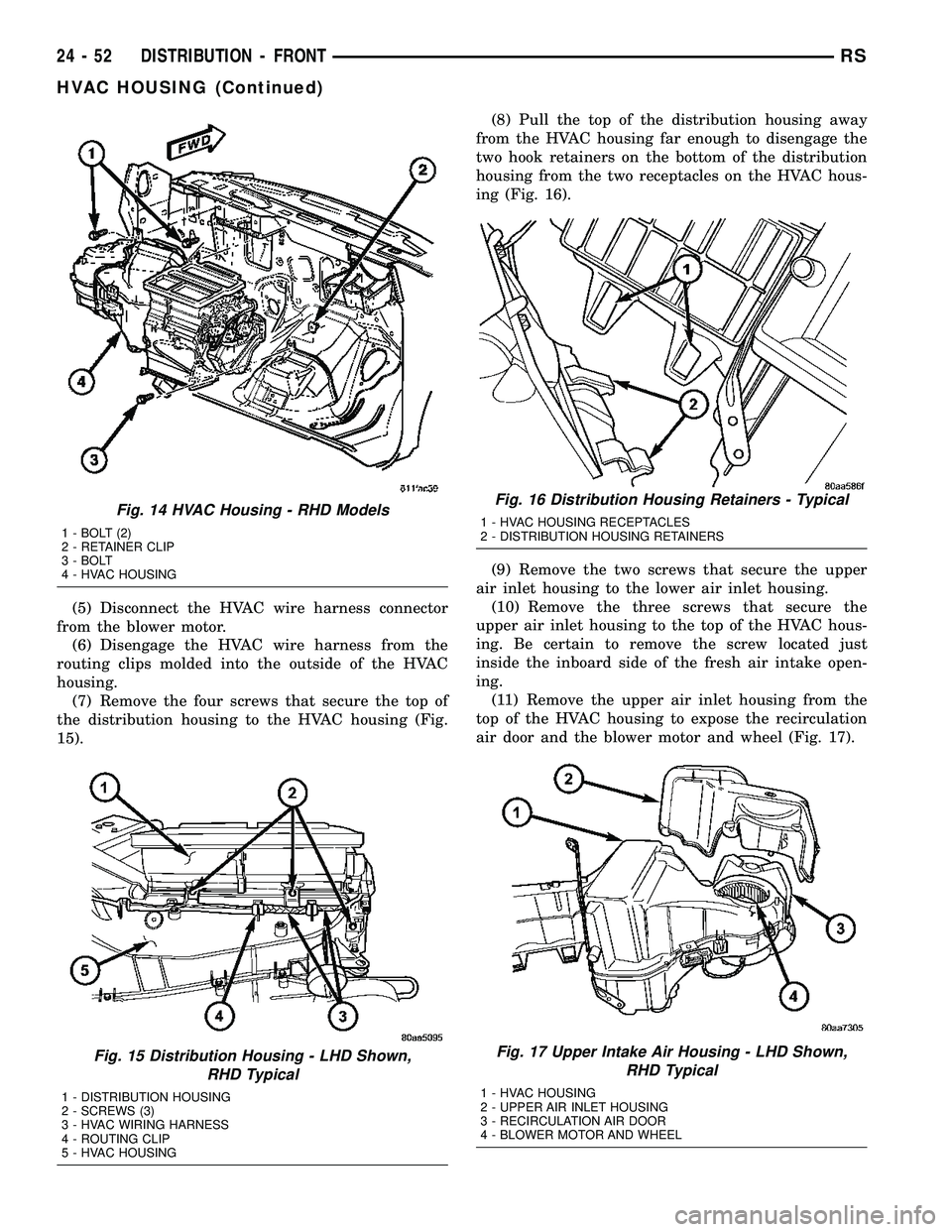
(7) Remove the four screws that secure the top of
the distribution housing to the HVAC housing (Fig.
15).(8) Pull the top of the distribution housing away
from the HVAC housing far enough to disengage the
two hook retainers on the bottom of the distribution
housing from the two receptacles on the HVAC hous-
ing (Fig. 16).
(9) Remove the two screws that secure the upper
air inlet housing to the lower air inlet housing.
(10) Remove the three screws that secure the
upper air inlet housing to the top of the HVAC hous-
ing. Be certain to remove the screw located just
inside the inboard side of the fresh air intake open-
ing.
(11) Remove the upper air inlet housing from the
top of the HVAC housing to expose the recirculation
air door and the blower motor and wheel (Fig. 17).
Fig. 15 Distribution Housing - LHD Shown,
RHD Typical
1 - DISTRIBUTION HOUSING
2 - SCREWS (3)
3 - HVAC WIRING HARNESS
4 - ROUTING CLIP
5 - HVAC HOUSING
Fig. 14 HVAC Housing - RHD Models
1 - BOLT (2)
2 - RETAINER CLIP
3 - BOLT
4 - HVAC HOUSING
Fig. 16 Distribution Housing Retainers - Typical
1 - HVAC HOUSING RECEPTACLES
2 - DISTRIBUTION HOUSING RETAINERS
Fig. 17 Upper Intake Air Housing - LHD Shown,
RHD Typical
1 - HVAC HOUSING
2 - UPPER AIR INLET HOUSING
3 - RECIRCULATION AIR DOOR
4 - BLOWER MOTOR AND WHEEL
24 - 52 DISTRIBUTION - FRONTRS
HVAC HOUSING (Continued)