2005 CHRYSLER CARAVAN steering
[x] Cancel search: steeringPage 1577 of 2339
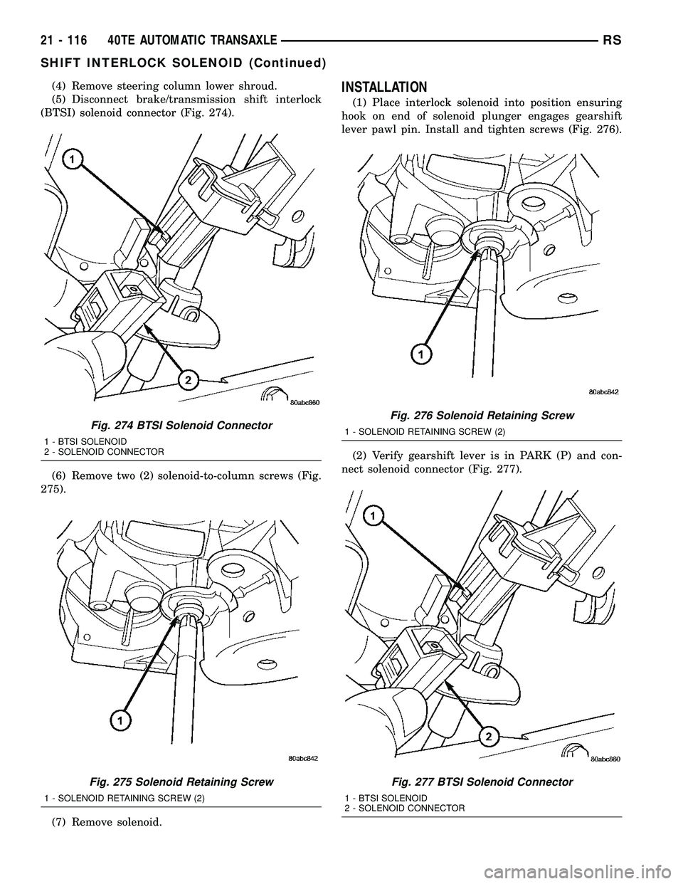
(4) Remove steering column lower shroud.
(5) Disconnect brake/transmission shift interlock
(BTSI) solenoid connector (Fig. 274).
(6) Remove two (2) solenoid-to-column screws (Fig.
275).
(7) Remove solenoid.INSTALLATION
(1) Place interlock solenoid into position ensuring
hook on end of solenoid plunger engages gearshift
lever pawl pin. Install and tighten screws (Fig. 276).
(2) Verify gearshift lever is in PARK (P) and con-
nect solenoid connector (Fig. 277).
Fig. 274 BTSI Solenoid Connector
1 - BTSI SOLENOID
2 - SOLENOID CONNECTOR
Fig. 275 Solenoid Retaining Screw
1 - SOLENOID RETAINING SCREW (2)
Fig. 276 Solenoid Retaining Screw
1 - SOLENOID RETAINING SCREW (2)
Fig. 277 BTSI Solenoid Connector
1 - BTSI SOLENOID
2 - SOLENOID CONNECTOR
21 - 116 40TE AUTOMATIC TRANSAXLERS
SHIFT INTERLOCK SOLENOID (Continued)
Page 1578 of 2339
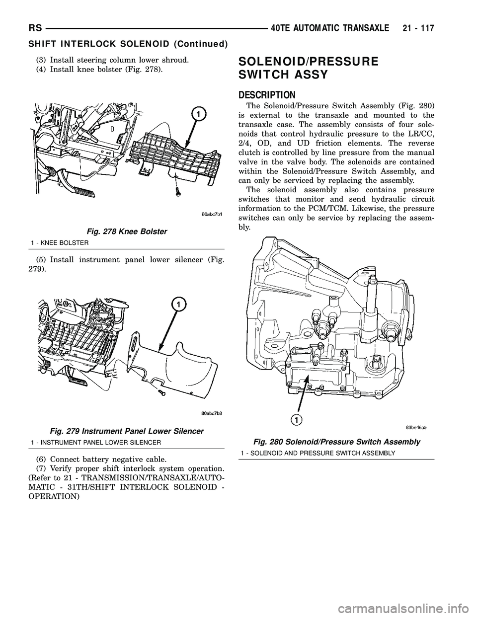
(3) Install steering column lower shroud.
(4) Install knee bolster (Fig. 278).
(5) Install instrument panel lower silencer (Fig.
279).
(6) Connect battery negative cable.
(7) Verify proper shift interlock system operation.
(Refer to 21 - TRANSMISSION/TRANSAXLE/AUTO-
MATIC - 31TH/SHIFT INTERLOCK SOLENOID -
OPERATION)SOLENOID/PRESSURE
SWITCH ASSY
DESCRIPTION
The Solenoid/Pressure Switch Assembly (Fig. 280)
is external to the transaxle and mounted to the
transaxle case. The assembly consists of four sole-
noids that control hydraulic pressure to the LR/CC,
2/4, OD, and UD friction elements. The reverse
clutch is controlled by line pressure from the manual
valve in the valve body. The solenoids are contained
within the Solenoid/Pressure Switch Assembly, and
can only be serviced by replacing the assembly.
The solenoid assembly also contains pressure
switches that monitor and send hydraulic circuit
information to the PCM/TCM. Likewise, the pressure
switches can only be service by replacing the assem-
bly.
Fig. 278 Knee Bolster
1 - KNEE BOLSTER
Fig. 279 Instrument Panel Lower Silencer
1 - INSTRUMENT PANEL LOWER SILENCERFig. 280 Solenoid/Pressure Switch Assembly
1 - SOLENOID AND PRESSURE SWITCH ASSEMBLY
RS40TE AUTOMATIC TRANSAXLE21 - 117
SHIFT INTERLOCK SOLENOID (Continued)
Page 1725 of 2339
SEAL - OIL PUMP
REMOVAL
(1) Remove transaxle from vehicle (Refer to 21 -
TRANSMISSION/TRANSAXLE/AUTOMATIC - 41TE
- REMOVAL).
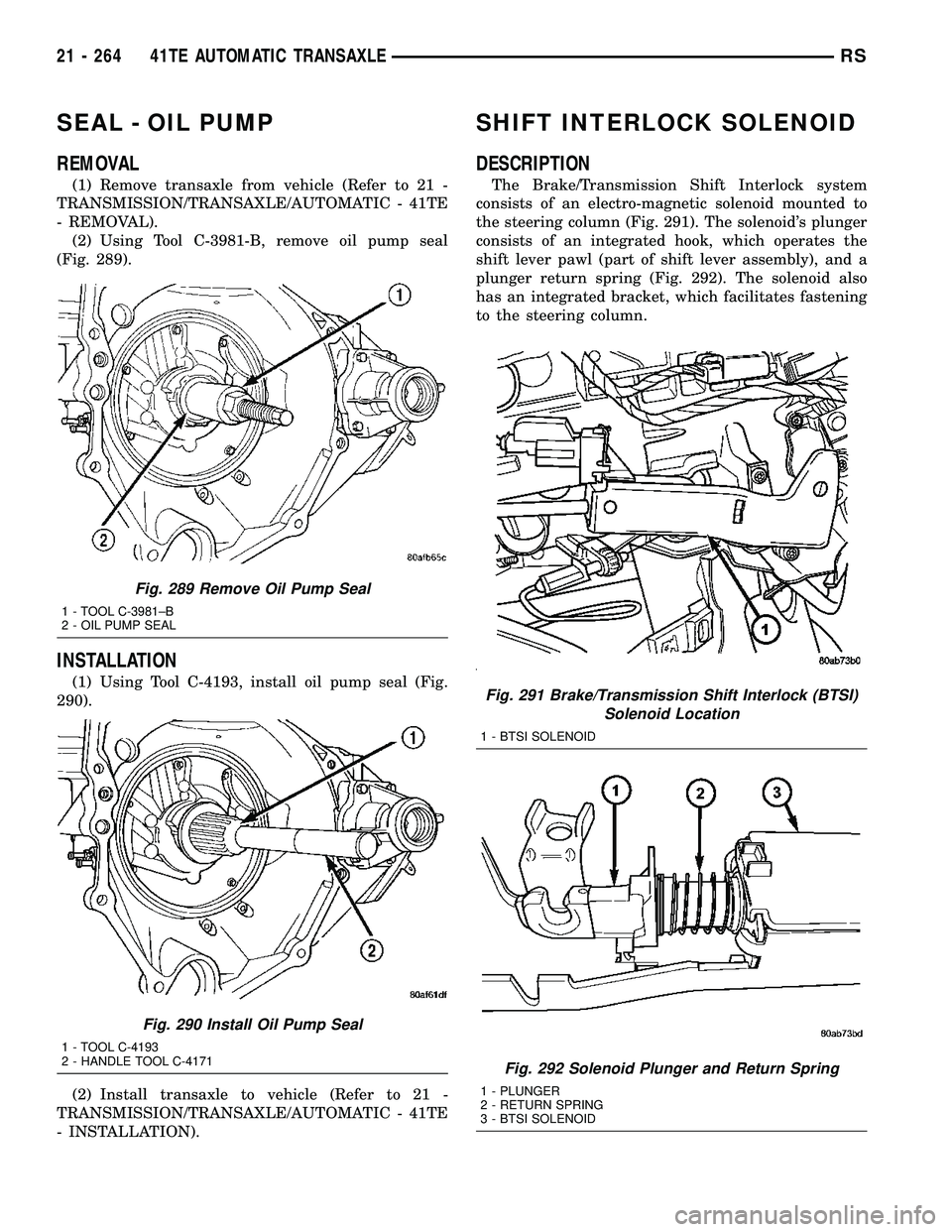
(2) Using Tool C-3981-B, remove oil pump seal
(Fig. 289).
INSTALLATION
(1) Using Tool C-4193, install oil pump seal (Fig.
290).
(2) Install transaxle to vehicle (Refer to 21 -
TRANSMISSION/TRANSAXLE/AUTOMATIC - 41TE
- INSTALLATION).
SHIFT INTERLOCK SOLENOID
DESCRIPTION
The Brake/Transmission Shift Interlock system
consists of an electro-magnetic solenoid mounted to
the steering column (Fig. 291). The solenoid's plunger
consists of an integrated hook, which operates the
shift lever pawl (part of shift lever assembly), and a
plunger return spring (Fig. 292). The solenoid also
has an integrated bracket, which facilitates fastening
to the steering column.
Fig. 289 Remove Oil Pump Seal
1 - TOOL C-3981±B
2 - OIL PUMP SEAL
Fig. 290 Install Oil Pump Seal
1 - TOOL C-4193
2 - HANDLE TOOL C-4171
Fig. 291 Brake/Transmission Shift Interlock (BTSI)
Solenoid Location
1 - BTSI SOLENOID
Fig. 292 Solenoid Plunger and Return Spring
1 - PLUNGER
2 - RETURN SPRING
3 - BTSI SOLENOID
21 - 264 41TE AUTOMATIC TRANSAXLERS
Page 1728 of 2339
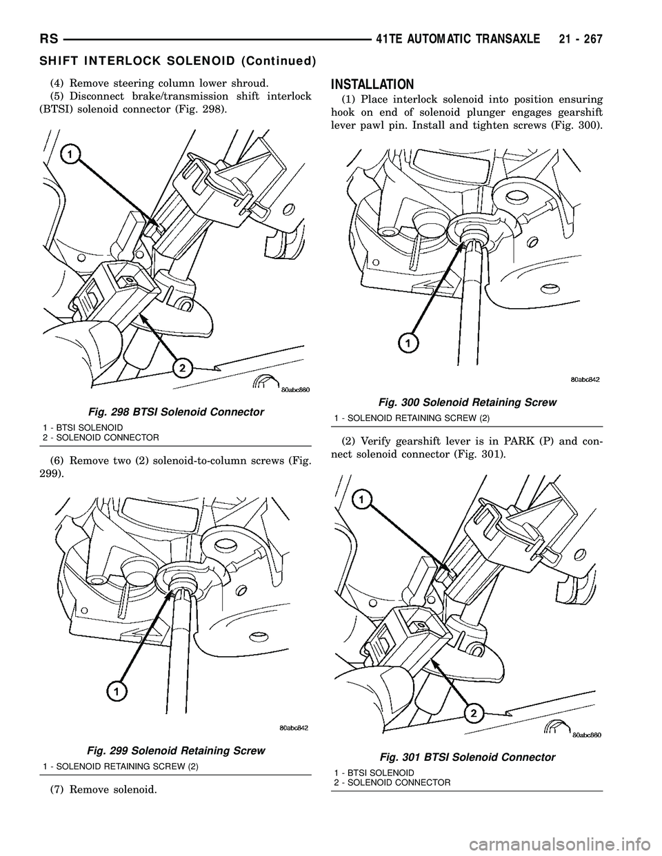
(4) Remove steering column lower shroud.
(5) Disconnect brake/transmission shift interlock
(BTSI) solenoid connector (Fig. 298).
(6) Remove two (2) solenoid-to-column screws (Fig.
299).
(7) Remove solenoid.INSTALLATION
(1) Place interlock solenoid into position ensuring
hook on end of solenoid plunger engages gearshift
lever pawl pin. Install and tighten screws (Fig. 300).
(2) Verify gearshift lever is in PARK (P) and con-
nect solenoid connector (Fig. 301).
Fig. 298 BTSI Solenoid Connector
1 - BTSI SOLENOID
2 - SOLENOID CONNECTOR
Fig. 299 Solenoid Retaining Screw
1 - SOLENOID RETAINING SCREW (2)
Fig. 300 Solenoid Retaining Screw
1 - SOLENOID RETAINING SCREW (2)
Fig. 301 BTSI Solenoid Connector
1 - BTSI SOLENOID
2 - SOLENOID CONNECTOR
RS41TE AUTOMATIC TRANSAXLE21 - 267
SHIFT INTERLOCK SOLENOID (Continued)
Page 1729 of 2339
(3) Install steering column lower shroud.
(4) Install knee bolster (Fig. 302).
(5) Install instrument panel lower silencer (Fig.
303).
(6) Connect battery negative cable.
(7) Verify proper shift interlock system operation.
(Refer to 21 - TRANSMISSION/TRANSAXLE/AUTO-
MATIC - 31TH/SHIFT INTERLOCK SOLENOID -
OPERATION)
SOLENOID/PRESSURE
SWITCH ASSY
DESCRIPTION
The Solenoid/Pressure Switch Assembly (Fig. 304)
is external to the transaxle and mounted to thetransaxle case. The assembly consists of four sole-
noids that control hydraulic pressure to the LR/CC,
2/4, OD, and UD friction elements. The reverse
clutch is controlled by line pressure from the manual
valve in the valve body. The solenoids are contained
within the Solenoid/Pressure Switch Assembly, and
can only be serviced by replacing the assembly.
The solenoid assembly also contains pressure
switches that monitor and send hydraulic circuit
information to the PCM/TCM. Likewise, the pressure
switches can only be service by replacing the assem-
bly.
OPERATION
SOLENOIDS
The solenoids receive electrical power from the
Transmission Control Relay through a single wire.
The PCM/TCM energizes or operates the solenoids
individually by grounding the return wire of the sole-
noid needed. When a solenoid is energized, the sole-
noid valve shifts, and a fluid passage is opened or
closed (vented or applied), depending on its default
operating state. The result is an apply or release of a
frictional element.
The 2/4 and UD solenoids are normally applied,
which by design allow fluid to pass through in their
relaxed or ªoffº state. This allows transaxle limp-in
(P,R,N,2) in the event of an electrical failure.
The continuity of the solenoids and circuits are
periodically tested. Each solenoid is turned on or off
depending on its current state. An inductive spike
Fig. 302 Knee Bolster
1 - KNEE BOLSTER
Fig. 303 Instrument Panel Lower Silencer
1 - INSTRUMENT PANEL LOWER SILENCER
Fig. 304 Solenoid/Pressure Switch Assembly
1 - SOLENOID AND PRESSURE SWITCH ASSEMBLY
21 - 268 41TE AUTOMATIC TRANSAXLERS
SHIFT INTERLOCK SOLENOID (Continued)
Page 1758 of 2339
TIRES/WHEELS
TABLE OF CONTENTS
page page
TIRES/WHEELS
DIAGNOSIS AND TESTING - TIRE AND
WHEEL VIBRATION.....................1
STANDARD PROCEDURE
STANDARD PROCEDURE - TIRE AND
WHEEL BALANCE......................5
STANDARD PROCEDURE - TIRE AND
WHEEL MATCH MOUNTING..............7
STANDARD PROCEDURE - TIRE AND
WHEEL ROTATION.....................7
REMOVAL
REMOVAL - TIRE AND WHEEL ASSEMBLY
(ALUMINUM WHEEL)....................8
REMOVAL - TIRE AND WHEEL ASSEMBLY
(STEEL WHEEL).......................8
INSTALLATION
INSTALLATION - TIRE AND WHEEL
ASSEMBLY (ALUMINUM WHEEL)..........8
INSTALLATION - TIRE AND WHEEL
ASSEMBLY (STEEL WHEEL)..............8
TIRE PRESSURE MONITORING
DESCRIPTION..........................9
OPERATION...........................10
SENSOR - TPM
DESCRIPTION.........................10
OPERATION...........................10
CAUTION.............................11
DIAGNOSIS AND TESTING - TIRE PRESSURE
SENSOR............................11
REMOVAL.............................11
INSTALLATION.........................11
TIRES
DESCRIPTION
DESCRIPTION - TIRE..................13
DESCRIPTION - RADIAL-PLY TIRES.......13
DESCRIPTION - REPLACEMENT TIRES....14
DESCRIPTION - SPARE TIRE
(TEMPORARY).......................14DIAGNOSIS AND TESTING
DIAGNOSIS AND TESTING - TIRE NOISE . . . 14
DIAGNOSIS AND TESTING - TIRE/VEHICLE
LEAD...............................14
DIAGNOSIS AND TESTING - TIRE WEAR
PATTERNS..........................16
DIAGNOSIS AND TESTING - TREAD WEAR
INDICATORS.........................16
STANDARD PROCEDURE
STANDARD PROCEDURE - TIRE INFLATION
PRESSURES.........................16
STANDARD PROCEDURE - TIRE
PRESSURE FOR HIGH SPEED
OPERATION.........................17
STANDARD PROCEDURE - TIRE LEAK
REPAIRING..........................17
CLEANING - TIRES.....................18
WHEELS
DESCRIPTION - WHEEL..................18
DIAGNOSIS AND TESTING - WHEEL
INSPECTION.........................19
CLEANING
WHEEL AND WHEEL TRIM CARE.........19
SPECIFICATIONS
WHEEL.............................19
WHEEL COVER
DESCRIPTION.........................19
REMOVAL.............................19
INSTALLATION.........................20
WHEEL MOUNTING STUDS - FRONT
REMOVAL.............................21
INSTALLATION.........................21
WHEEL MOUNTING STUDS - REAR
REMOVAL.............................22
INSTALLATION.........................22
TIRES/WHEELS
DIAGNOSIS AND TESTING - TIRE AND WHEEL
VIBRATION
Tire and wheel imbalance, runout and force varia-
tion can cause vehicles to exhibit steering wheel
vibration.
VISUAL INSPECTION
Visual inspection of the vehicle is recommended
prior to road testing or performing any other proce-
dure. Raise vehicle on a suitable hoist. (Refer to
LUBRICATION & MAINTENANCE/HOISTING -
STANDARD PROCEDURE)
Inspect for the following:
²Verify correct (OEM) wheel and tire, as well as
correct wheel weights. Aluminum wheels require
RSTIRES/WHEELS22-1
Page 1759 of 2339
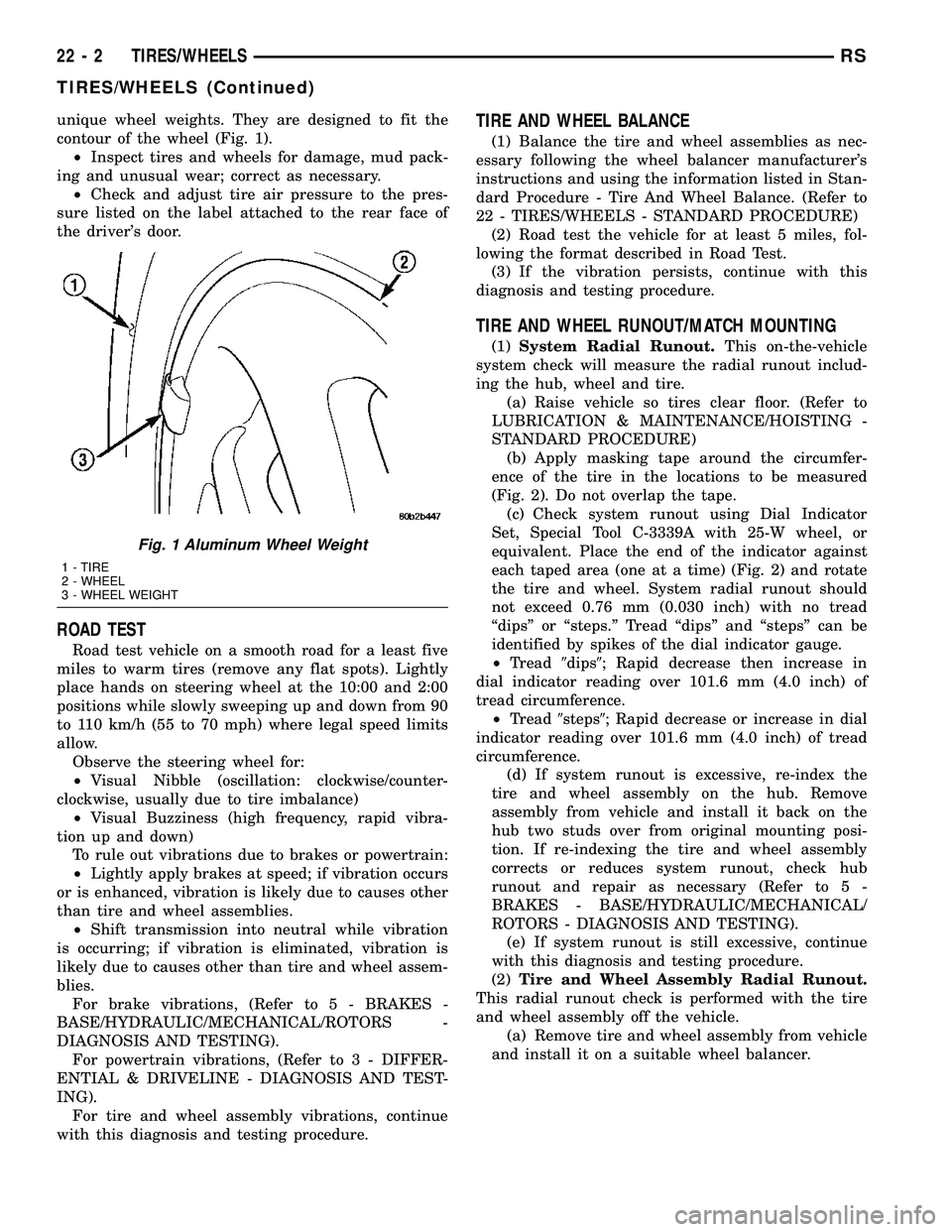
unique wheel weights. They are designed to fit the
contour of the wheel (Fig. 1).
²Inspect tires and wheels for damage, mud pack-
ing and unusual wear; correct as necessary.
²Check and adjust tire air pressure to the pres-
sure listed on the label attached to the rear face of
the driver's door.
ROAD TEST
Road test vehicle on a smooth road for a least five
miles to warm tires (remove any flat spots). Lightly
place hands on steering wheel at the 10:00 and 2:00
positions while slowly sweeping up and down from 90
to 110 km/h (55 to 70 mph) where legal speed limits
allow.
Observe the steering wheel for:
²Visual Nibble (oscillation: clockwise/counter-
clockwise, usually due to tire imbalance)
²Visual Buzziness (high frequency, rapid vibra-
tion up and down)
To rule out vibrations due to brakes or powertrain:
²Lightly apply brakes at speed; if vibration occurs
or is enhanced, vibration is likely due to causes other
than tire and wheel assemblies.
²Shift transmission into neutral while vibration
is occurring; if vibration is eliminated, vibration is
likely due to causes other than tire and wheel assem-
blies.
For brake vibrations, (Refer to 5 - BRAKES -
BASE/HYDRAULIC/MECHANICAL/ROTORS -
DIAGNOSIS AND TESTING).
For powertrain vibrations, (Refer to 3 - DIFFER-
ENTIAL & DRIVELINE - DIAGNOSIS AND TEST-
ING).
For tire and wheel assembly vibrations, continue
with this diagnosis and testing procedure.
TIRE AND WHEEL BALANCE
(1) Balance the tire and wheel assemblies as nec-
essary following the wheel balancer manufacturer's
instructions and using the information listed in Stan-
dard Procedure - Tire And Wheel Balance. (Refer to
22 - TIRES/WHEELS - STANDARD PROCEDURE)
(2) Road test the vehicle for at least 5 miles, fol-
lowing the format described in Road Test.
(3) If the vibration persists, continue with this
diagnosis and testing procedure.
TIRE AND WHEEL RUNOUT/MATCH MOUNTING
(1)System Radial Runout.This on-the-vehicle
system check will measure the radial runout includ-
ing the hub, wheel and tire.
(a) Raise vehicle so tires clear floor. (Refer to
LUBRICATION & MAINTENANCE/HOISTING -
STANDARD PROCEDURE)
(b) Apply masking tape around the circumfer-
ence of the tire in the locations to be measured
(Fig. 2). Do not overlap the tape.
(c) Check system runout using Dial Indicator
Set, Special Tool C-3339A with 25-W wheel, or
equivalent. Place the end of the indicator against
each taped area (one at a time) (Fig. 2) and rotate
the tire and wheel. System radial runout should
not exceed 0.76 mm (0.030 inch) with no tread
ªdipsº or ªsteps.º Tread ªdipsº and ªstepsº can be
identified by spikes of the dial indicator gauge.
²Tread9dips9; Rapid decrease then increase in
dial indicator reading over 101.6 mm (4.0 inch) of
tread circumference.
²Tread9steps9; Rapid decrease or increase in dial
indicator reading over 101.6 mm (4.0 inch) of tread
circumference.
(d) If system runout is excessive, re-index the
tire and wheel assembly on the hub. Remove
assembly from vehicle and install it back on the
hub two studs over from original mounting posi-
tion. If re-indexing the tire and wheel assembly
corrects or reduces system runout, check hub
runout and repair as necessary (Refer to 5 -
BRAKES - BASE/HYDRAULIC/MECHANICAL/
ROTORS - DIAGNOSIS AND TESTING).
(e) If system runout is still excessive, continue
with this diagnosis and testing procedure.
(2)Tire and Wheel Assembly Radial Runout.
This radial runout check is performed with the tire
and wheel assembly off the vehicle.
(a) Remove tire and wheel assembly from vehicle
and install it on a suitable wheel balancer.
Fig. 1 Aluminum Wheel Weight
1 - TIRE
2 - WHEEL
3 - WHEEL WEIGHT
22 - 2 TIRES/WHEELSRS
TIRES/WHEELS (Continued)
Page 1771 of 2339
Radial-ply tires must always be used in sets of four
and under no circumstances should they be used on
the front only. It is recommended that tires from dif-
ferent manufacturers NOT be mixed. They may be
mixed with a temporary spare tire when necessary. A
maximum speed of 80 km/h (50 mph) is recom-
mended while a temporary spare is in use.
Radial-ply tires have the same load-carrying capac-
ity as other types of tires of the same size. They also
use the same recommended inflation pressures.
DESCRIPTION - REPLACEMENT TIRES
WARNING: FAILURE TO EQUIP THE VEHICLE WITH
TIRES HAVING ADEQUATE SPEED CAPABILITY
CAN RESULT IN SUDDEN TIRE FAILURE.
WARNING: IN ORDER TO MAINTAIN THE SPEED
CAPABILITY OF THE VEHICLE, REPLACEMENT
TIRES MUST HAVE SPEED RATINGS EQUAL TO OR
HIGHER THAN THOSE FITTED TO THE VEHICLE AS
ORIGINAL EQUIPMENT. IF TIRES WITH LOWER
SPEED RATINGS ARE FITTED, THE VEHICLE'S
HANDLING MAY BE AFFECTED AND THE SPEED
CAPABILITY OF THE VEHICLE MAY BE LOWERED
TO THE MAXIMUM SPEED CAPABILITY OF THE
REPLACEMENT TIRES. TO AVOID AN ACCIDENT
RESULTING IN SEVERE OR FATAL INJURY, CON-
SULT THE TIRE MANUFACTURER IN REGARDS TO
MAXIMUM SPEED RATINGS.
It is recommended that tires equivalent to the orig-
inal equipment tires be used when replacement is
needed.
Failure to use equivalent replacement tires may
adversely affect the safety and handling of the vehi-
cle.
The original equipment tires provide a proper com-
bination of many characteristics such as:
²Ride
²Noise
²Handling
²Durability
²Tread life²Traction
²Rolling resistance
²Speed capability
The use of tires smaller than the minimum tire
size approved for the vehicle can result in tire over-
loading and failure.
Use tires that have the approved load rating for
the vehicle and never overload them. Failure to equip
the vehicle with tires having adequate speed capabil-
ity can result in sudden tire failure and loss of vehi-
cle control.
The use of oversize tires may cause interference
with vehicle components. Under extremes of suspen-
sion and steering travel, interference with vehicle
components may cause tire damage.
DESCRIPTION - SPARE TIRE (TEMPORARY)
The temporary (convenience) spare tire is designed
for emergency use only. The original tire should be
repaired and reinstalled, or replaced with a new, at
the first opportunity.
The temporary (convenience) spare tire should be
inflated to the pressure listed on its sidewall. Do not
exceed speeds of 80 km/h (50 mph) when the tempo-
rary spare tire is in use on the vehicle. Refer to the
Owner's Manual for more details.
DIAGNOSIS AND TESTING
DIAGNOSIS AND TESTING - TIRE NOISE
Unusual tire noise can be associated with tire and
wheel vibration or irregular tire wear. For vibration,
(Refer to 22 - TIRES/WHEELS - DIAGNOSIS AND
TESTING). For irregular tire wear, (Refer to 22 -
TIRES/WHEELS/TIRES - DIAGNOSIS AND TEST-
ING).
DIAGNOSIS AND TESTING - TIRE/VEHICLE
LEAD
Use the following Vehicle Lead Diagnosis And Cor-
rection Chart to diagnose and correct a vehicle lead
or drift problem.
22 - 14 TIRES/WHEELSRS
TIRES (Continued)