2005 CHRYSLER CARAVAN brake
[x] Cancel search: brakePage 1115 of 2339
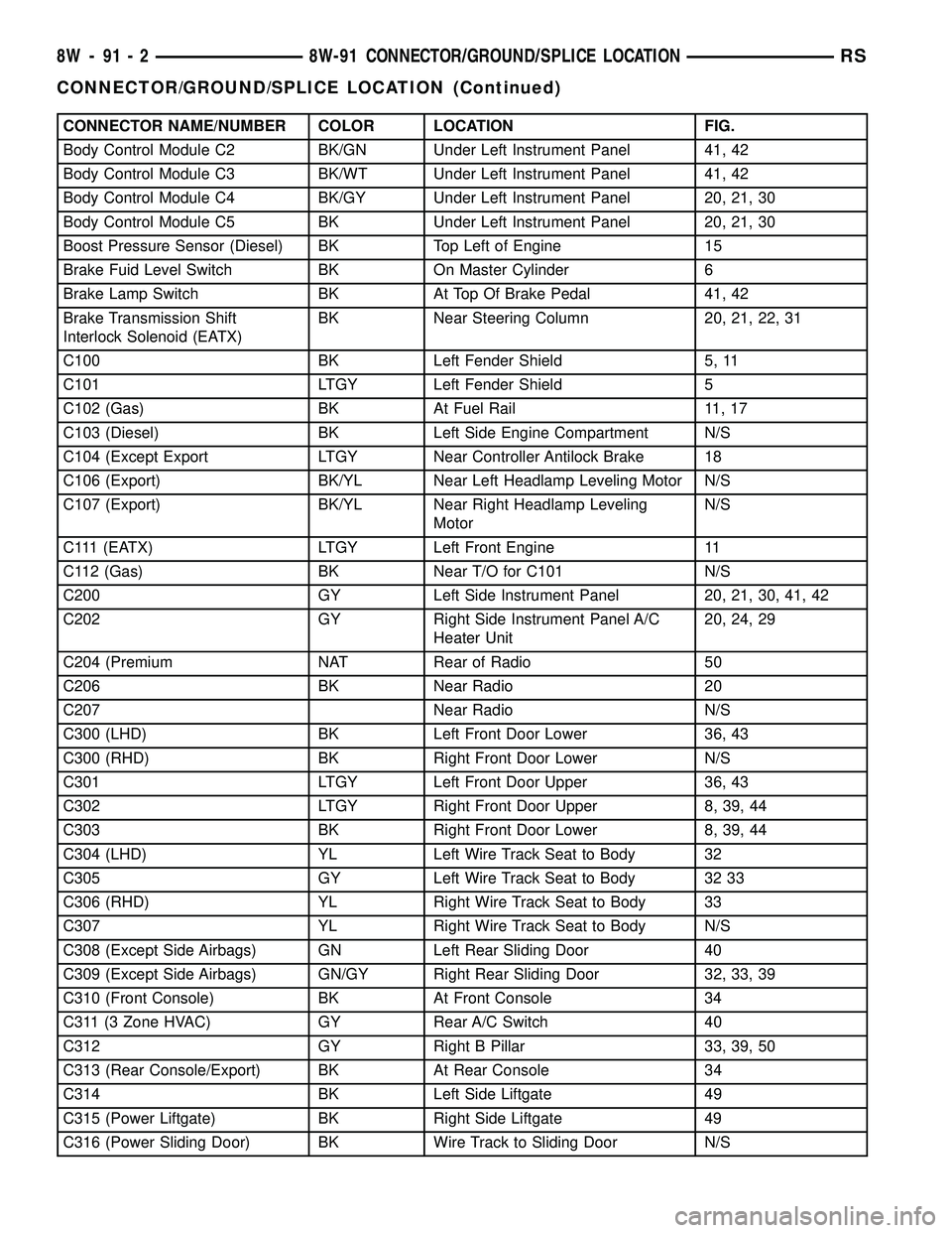
CONNECTOR NAME/NUMBER COLOR LOCATION FIG.
Body Control Module C2 BK/GN Under Left Instrument Panel 41, 42
Body Control Module C3 BK/WT Under Left Instrument Panel 41, 42
Body Control Module C4 BK/GY Under Left Instrument Panel 20, 21, 30
Body Control Module C5 BK Under Left Instrument Panel 20, 21, 30
Boost Pressure Sensor (Diesel) BK Top Left of Engine 15
Brake Fuid Level Switch BK On Master Cylinder 6
Brake Lamp Switch BK At Top Of Brake Pedal 41, 42
Brake Transmission Shift
Interlock Solenoid (EATX)BK Near Steering Column 20, 21, 22, 31
C100 BK Left Fender Shield 5, 11
C101 LTGY Left Fender Shield 5
C102 (Gas) BK At Fuel Rail 11, 17
C103 (Diesel) BK Left Side Engine Compartment N/S
C104 (Except Export LTGY Near Controller Antilock Brake 18
C106 (Export) BK/YL Near Left Headlamp Leveling Motor N/S
C107 (Export) BK/YL Near Right Headlamp Leveling
MotorN/S
C111 (EATX) LTGY Left Front Engine 11
C112 (Gas) BK Near T/O for C101 N/S
C200 GY Left Side Instrument Panel 20, 21, 30, 41, 42
C202 GY Right Side Instrument Panel A/C
Heater Unit20, 24, 29
C204 (Premium NAT Rear of Radio 50
C206 BK Near Radio 20
C207 Near Radio N/S
C300 (LHD) BK Left Front Door Lower 36, 43
C300 (RHD) BK Right Front Door Lower N/S
C301 LTGY Left Front Door Upper 36, 43
C302 LTGY Right Front Door Upper 8, 39, 44
C303 BK Right Front Door Lower 8, 39, 44
C304 (LHD) YL Left Wire Track Seat to Body 32
C305 GY Left Wire Track Seat to Body 32 33
C306 (RHD) YL Right Wire Track Seat to Body 33
C307 YL Right Wire Track Seat to Body N/S
C308 (Except Side Airbags) GN Left Rear Sliding Door 40
C309 (Except Side Airbags) GN/GY Right Rear Sliding Door 32, 33, 39
C310 (Front Console) BK At Front Console 34
C311 (3 Zone HVAC) GY Rear A/C Switch 40
C312 GY Right B Pillar 33, 39, 50
C313 (Rear Console/Export) BK At Rear Console 34
C314 BK Left Side Liftgate 49
C315 (Power Liftgate) BK Right Side Liftgate 49
C316 (Power Sliding Door) BK Wire Track to Sliding Door N/S
8W - 91 - 2 8W-91 CONNECTOR/GROUND/SPLICE LOCATIONRS
CONNECTOR/GROUND/SPLICE LOCATION (Continued)
Page 1116 of 2339
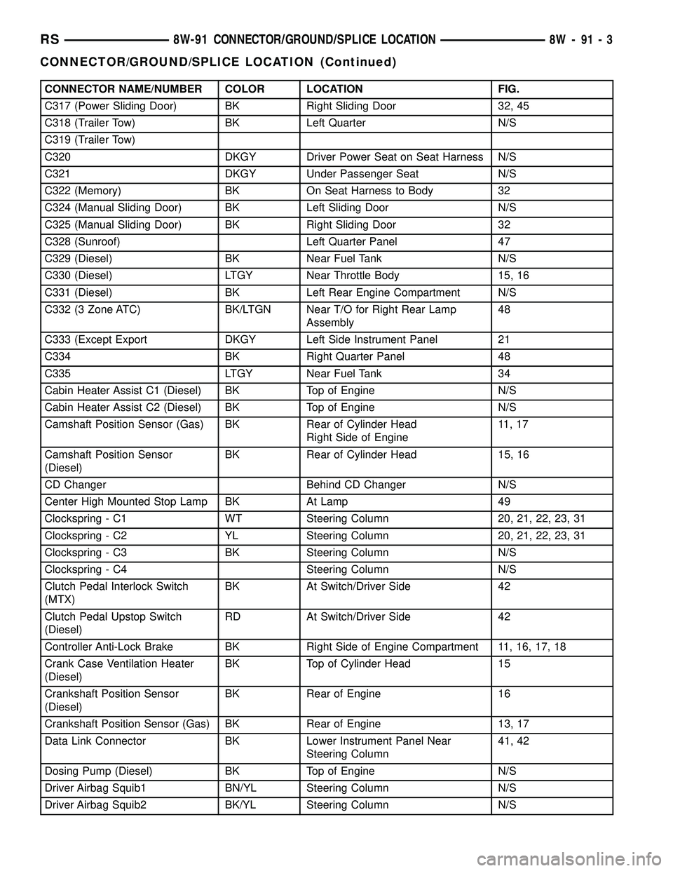
CONNECTOR NAME/NUMBER COLOR LOCATION FIG.
C317 (Power Sliding Door) BK Right Sliding Door 32, 45
C318 (Trailer Tow) BK Left Quarter N/S
C319 (Trailer Tow)
C320 DKGY Driver Power Seat on Seat Harness N/S
C321 DKGY Under Passenger Seat N/S
C322 (Memory) BK On Seat Harness to Body 32
C324 (Manual Sliding Door) BK Left Sliding Door N/S
C325 (Manual Sliding Door) BK Right Sliding Door 32
C328 (Sunroof) Left Quarter Panel 47
C329 (Diesel) BK Near Fuel Tank N/S
C330 (Diesel) LTGY Near Throttle Body 15, 16
C331 (Diesel) BK Left Rear Engine Compartment N/S
C332 (3 Zone ATC) BK/LTGN Near T/O for Right Rear Lamp
Assembly48
C333 (Except Export DKGY Left Side Instrument Panel 21
C334 BK Right Quarter Panel 48
C335 LTGY Near Fuel Tank 34
Cabin Heater Assist C1 (Diesel) BK Top of Engine N/S
Cabin Heater Assist C2 (Diesel) BK Top of Engine N/S
Camshaft Position Sensor (Gas) BK Rear of Cylinder Head
Right Side of Engine11 , 1 7
Camshaft Position Sensor
(Diesel)BK Rear of Cylinder Head 15, 16
CD Changer Behind CD Changer N/S
Center High Mounted Stop Lamp BK At Lamp 49
Clockspring - C1 WT Steering Column 20, 21, 22, 23, 31
Clockspring - C2 YL Steering Column 20, 21, 22, 23, 31
Clockspring - C3 BK Steering Column N/S
Clockspring - C4 Steering Column N/S
Clutch Pedal Interlock Switch
(MTX)BK At Switch/Driver Side 42
Clutch Pedal Upstop Switch
(Diesel)RD At Switch/Driver Side 42
Controller Anti-Lock Brake BK Right Side of Engine Compartment 11, 16, 17, 18
Crank Case Ventilation Heater
(Diesel)BK Top of Cylinder Head 15
Crankshaft Position Sensor
(Diesel)BK Rear of Engine 16
Crankshaft Position Sensor (Gas) BK Rear of Engine 13, 17
Data Link Connector BK Lower Instrument Panel Near
Steering Column41, 42
Dosing Pump (Diesel) BK Top of Engine N/S
Driver Airbag Squib1 BN/YL Steering Column N/S
Driver Airbag Squib2 BK/YL Steering Column N/S
RS8W-91 CONNECTOR/GROUND/SPLICE LOCATION8W-91-3
CONNECTOR/GROUND/SPLICE LOCATION (Continued)
Page 1121 of 2339

CONNECTOR NAME/NUMBER COLOR LOCATION FIG.
Liftgate Ajar Switch (Manual
Release)BK At Latch 49
Liftgate Ajar Switch (Power
Release)BK Lower Liftgate 49
Liftgate Cinch/Release Motor
(Power Liftgate)BL Liftgate 49
Liftgate Left Pinch Sensor (Power
Liftgate)BK Left Side of Liftgate 49
Liftgate Right Pinch Sensor
(Power Liftgate)BK Right Side of Liftgate 49
Manifold Absolute Pressure
Sensor (Gas)BK On Intake N/S
Mass Air Flow Sensor (Diesel) OR Top of Engine 15, 16
Memory Seat/Mirror/Adjustable
Pedals Module C1GY Under Driver Seat N/S
Memory Seat/Mirror/ Adjustable
Pedals Module C2GY Under Driver Seat N/S
Memory Seat/Mirror/ Adjustable
Pedals Module C3WT Under Driver Seat N/S
Memory Seat/Mirror/ Adjustable
Pedals Module C4GY Under Driver Seat N/S
Memory Set Switch BK At Switch Driver Door 43
Message Center (Highline) WT Rear of Message Center 20, 21, 28
Mode Door Actuator GY Left Side of HVAC N/S
Multi Function Switch BK At Steering Column 20, 21, 22, 23, 31
Natural Vacuum Leak Detection
Assembly (Except Export)LTGY Top of Engine 12
Occupant Classification Module BK Passenger Seat N/S
Occupant Restraint Controller C1 YL Right Side Instrument Panel
Occupant Restraint Controller C2 YL Right Side Instrument Panel 20, 24, 25
Output Speed Sensor GY Front of Transmission 14, 19
Overhead Console (Except Base) BK Front of Console N/S
Oxygen Sensor 1/1 Upstream
(Gas)Rear of Engine 11, 12, 18
Oxygen Sensor 1/2 Downstream
(Gas)Rear of Engine 11, 12,18
Park Brake Switck Bottoom Left Side of Instrument
Panel20, 21
Park Sensor No.1 (Parktronics) Rear Fascia N/S
Park Sensor No.2 (Parktronics) Rear Fascia N/S
Park Sensor No.3 (Parktronics) Rear Fascia N/S
Park Sensor No.4 (Parktronics) Rear Fascia N/S
Passenger Airbag YL Passenger Side of Instrument Panel 20, 23, 24, 29
Passenger Airbag On/Off
Indicator LampRight Center of Instrument Panel 20, 23, 25
Passenger Blend Door Actuator GY On HVAC N/S
8W - 91 - 8 8W-91 CONNECTOR/GROUND/SPLICE LOCATIONRS
CONNECTOR/GROUND/SPLICE LOCATION (Continued)
Page 1125 of 2339
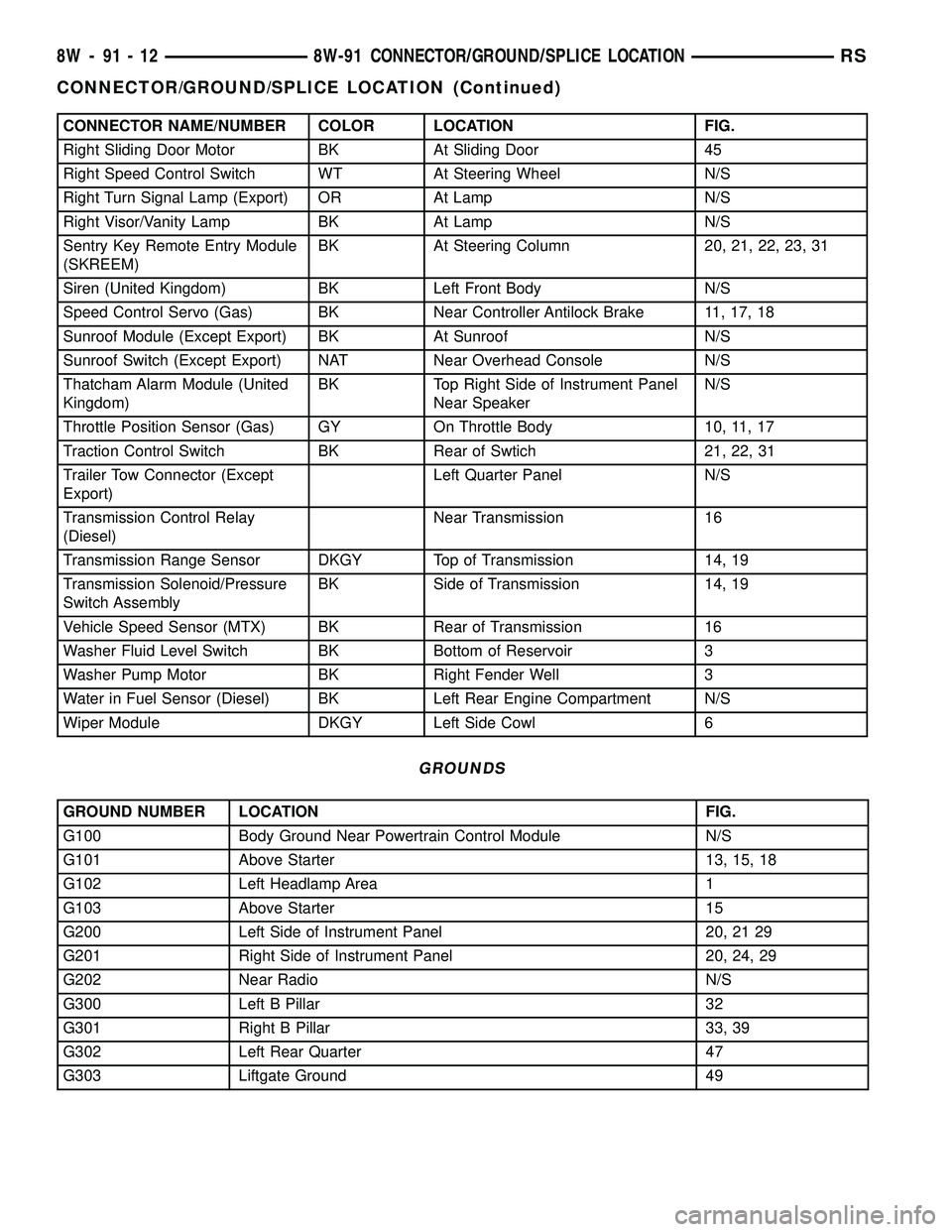
CONNECTOR NAME/NUMBER COLOR LOCATION FIG.
Right Sliding Door Motor BK At Sliding Door 45
Right Speed Control Switch WT At Steering Wheel N/S
Right Turn Signal Lamp (Export) OR At Lamp N/S
Right Visor/Vanity Lamp BK At Lamp N/S
Sentry Key Remote Entry Module
(SKREEM)BK At Steering Column 20, 21, 22, 23, 31
Siren (United Kingdom) BK Left Front Body N/S
Speed Control Servo (Gas) BK Near Controller Antilock Brake 11, 17, 18
Sunroof Module (Except Export) BK At Sunroof N/S
Sunroof Switch (Except Export) NAT Near Overhead Console N/S
Thatcham Alarm Module (United
Kingdom)BK Top Right Side of Instrument Panel
Near SpeakerN/S
Throttle Position Sensor (Gas) GY On Throttle Body 10, 11, 17
Traction Control Switch BK Rear of Swtich 21, 22, 31
Trailer Tow Connector (Except
Export)Left Quarter Panel N/S
Transmission Control Relay
(Diesel)Near Transmission 16
Transmission Range Sensor DKGY Top of Transmission 14, 19
Transmission Solenoid/Pressure
Switch AssemblyBK Side of Transmission 14, 19
Vehicle Speed Sensor (MTX) BK Rear of Transmission 16
Washer Fluid Level Switch BK Bottom of Reservoir 3
Washer Pump Motor BK Right Fender Well 3
Water in Fuel Sensor (Diesel) BK Left Rear Engine Compartment N/S
Wiper Module DKGY Left Side Cowl 6
GROUNDS
GROUND NUMBER LOCATION FIG.
G100 Body Ground Near Powertrain Control Module N/S
G101 Above Starter 13, 15, 18
G102 Left Headlamp Area 1
G103 Above Starter 15
G200 Left Side of Instrument Panel 20, 21 29
G201 Right Side of Instrument Panel 20, 24, 29
G202 Near Radio N/S
G300 Left B Pillar 32
G301 Right B Pillar 33, 39
G302 Left Rear Quarter 47
G303 Liftgate Ground 49
8W - 91 - 12 8W-91 CONNECTOR/GROUND/SPLICE LOCATIONRS
CONNECTOR/GROUND/SPLICE LOCATION (Continued)
Page 1127 of 2339
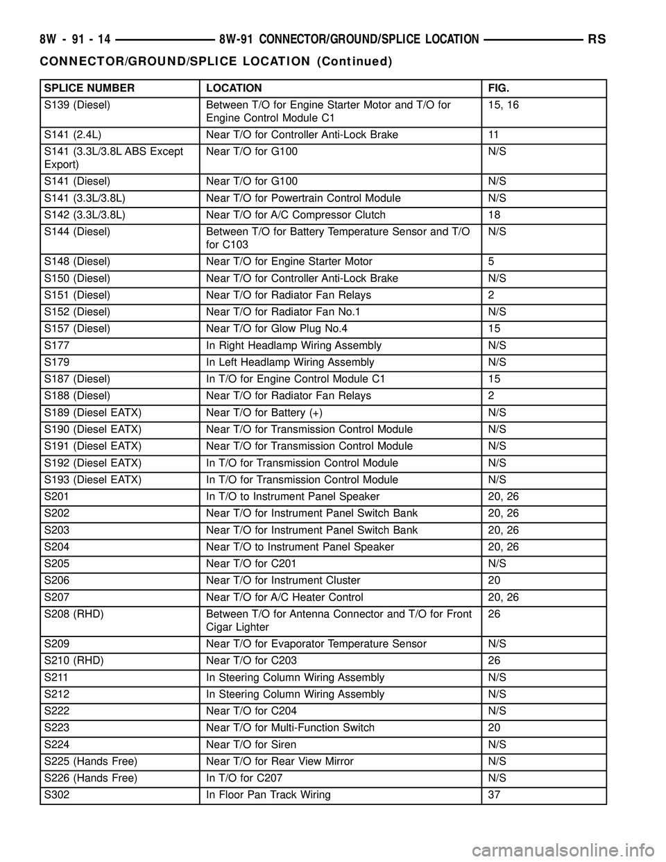
SPLICE NUMBER LOCATION FIG.
S139 (Diesel) Between T/O for Engine Starter Motor and T/O for
Engine Control Module C115, 16
S141 (2.4L) Near T/O for Controller Anti-Lock Brake 11
S141 (3.3L/3.8L ABS Except
Export)Near T/O for G100 N/S
S141 (Diesel) Near T/O for G100 N/S
S141 (3.3L/3.8L) Near T/O for Powertrain Control Module N/S
S142 (3.3L/3.8L) Near T/O for A/C Compressor Clutch 18
S144 (Diesel) Between T/O for Battery Temperature Sensor and T/O
for C103N/S
S148 (Diesel) Near T/O for Engine Starter Motor 5
S150 (Diesel) Near T/O for Controller Anti-Lock Brake N/S
S151 (Diesel) Near T/O for Radiator Fan Relays 2
S152 (Diesel) Near T/O for Radiator Fan No.1 N/S
S157 (Diesel) Near T/O for Glow Plug No.4 15
S177 In Right Headlamp Wiring Assembly N/S
S179 In Left Headlamp Wiring Assembly N/S
S187 (Diesel) In T/O for Engine Control Module C1 15
S188 (Diesel) Near T/O for Radiator Fan Relays 2
S189 (Diesel EATX) Near T/O for Battery (+) N/S
S190 (Diesel EATX) Near T/O for Transmission Control Module N/S
S191 (Diesel EATX) Near T/O for Transmission Control Module N/S
S192 (Diesel EATX) In T/O for Transmission Control Module N/S
S193 (Diesel EATX) In T/O for Transmission Control Module N/S
S201 In T/O to Instrument Panel Speaker 20, 26
S202 Near T/O for Instrument Panel Switch Bank 20, 26
S203 Near T/O for Instrument Panel Switch Bank 20, 26
S204 Near T/O to Instrument Panel Speaker 20, 26
S205 Near T/O for C201 N/S
S206 Near T/O for Instrument Cluster 20
S207 Near T/O for A/C Heater Control 20, 26
S208 (RHD) Between T/O for Antenna Connector and T/O for Front
Cigar Lighter26
S209 Near T/O for Evaporator Temperature Sensor N/S
S210 (RHD) Near T/O for C203 26
S211 In Steering Column Wiring Assembly N/S
S212 In Steering Column Wiring Assembly N/S
S222 Near T/O for C204 N/S
S223 Near T/O for Multi-Function Switch 20
S224 Near T/O for Siren N/S
S225 (Hands Free) Near T/O for Rear View Mirror N/S
S226 (Hands Free) In T/O for C207 N/S
S302 In Floor Pan Track Wiring 37
8W - 91 - 14 8W-91 CONNECTOR/GROUND/SPLICE LOCATIONRS
CONNECTOR/GROUND/SPLICE LOCATION (Continued)
Page 1216 of 2339
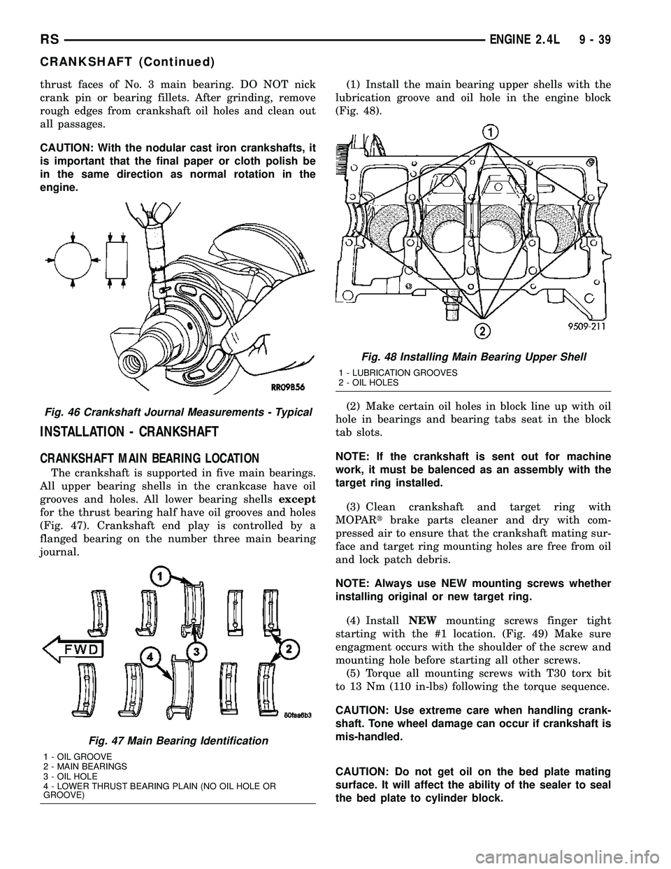
thrust faces of No. 3 main bearing. DO NOT nick
crank pin or bearing fillets. After grinding, remove
rough edges from crankshaft oil holes and clean out
all passages.
CAUTION: With the nodular cast iron crankshafts, it
is important that the final paper or cloth polish be
in the same direction as normal rotation in the
engine.
INSTALLATION - CRANKSHAFT
CRANKSHAFT MAIN BEARING LOCATION
The crankshaft is supported in five main bearings.
All upper bearing shells in the crankcase have oil
grooves and holes. All lower bearing shellsexcept
for the thrust bearing half have oil grooves and holes
(Fig. 47). Crankshaft end play is controlled by a
flanged bearing on the number three main bearing
journal.(1) Install the main bearing upper shells with the
lubrication groove and oil hole in the engine block
(Fig. 48).
(2) Make certain oil holes in block line up with oil
hole in bearings and bearing tabs seat in the block
tab slots.
NOTE: If the crankshaft is sent out for machine
work, it must be balenced as an assembly with the
target ring installed.
(3) Clean crankshaft and target ring with
MOPARtbrake parts cleaner and dry with com-
pressed air to ensure that the crankshaft mating sur-
face and target ring mounting holes are free from oil
and lock patch debris.
NOTE: Always use NEW mounting screws whether
installing original or new target ring.
(4) InstallNEWmounting screws finger tight
starting with the #1 location. (Fig. 49) Make sure
engagment occurs with the shoulder of the screw and
mounting hole before starting all other screws.
(5) Torque all mounting screws with T30 torx bit
to 13 Nm (110 in-lbs) following the torque sequence.
CAUTION: Use extreme care when handling crank-
shaft. Tone wheel damage can occur if crankshaft is
mis-handled.
CAUTION: Do not get oil on the bed plate mating
surface. It will affect the ability of the sealer to seal
the bed plate to cylinder block.
Fig. 46 Crankshaft Journal Measurements - Typical
Fig. 47 Main Bearing Identification
1 - OIL GROOVE
2 - MAIN BEARINGS
3 - OIL HOLE
4 - LOWER THRUST BEARING PLAIN (NO OIL HOLE OR
GROOVE)
Fig. 48 Installing Main Bearing Upper Shell
1 - LUBRICATION GROOVES
2 - OIL HOLES
RSENGINE 2.4L9-39
CRANKSHAFT (Continued)
Page 1232 of 2339
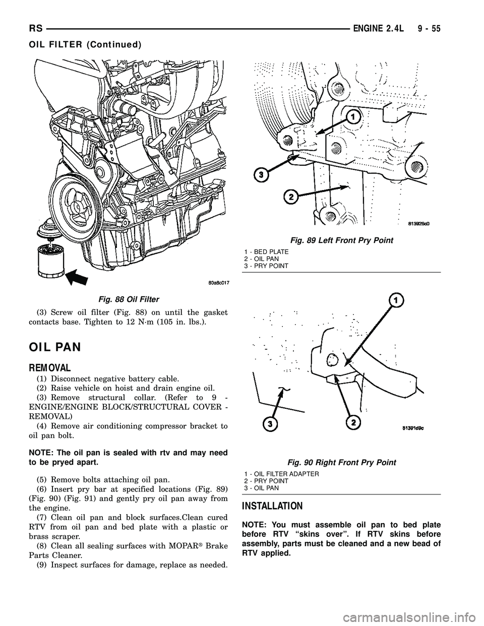
(3) Screw oil filter (Fig. 88) on until the gasket
contacts base. Tighten to 12 N´m (105 in. lbs.).
OIL PAN
REMOVAL
(1) Disconnect negative battery cable.
(2) Raise vehicle on hoist and drain engine oil.
(3) Remove structural collar. (Refer to 9 -
ENGINE/ENGINE BLOCK/STRUCTURAL COVER -
REMOVAL)
(4) Remove air conditioning compressor bracket to
oil pan bolt.
NOTE: The oil pan is sealed with rtv and may need
to be pryed apart.
(5) Remove bolts attaching oil pan.
(6) Insert pry bar at specified locations (Fig. 89)
(Fig. 90) (Fig. 91) and gently pry oil pan away from
the engine.
(7) Clean oil pan and block surfaces.Clean cured
RTV from oil pan and bed plate with a plastic or
brass scraper.
(8) Clean all sealing surfaces with MOPARtBrake
Parts Cleaner.
(9) Inspect surfaces for damage, replace as needed.
INSTALLATION
NOTE: You must assemble oil pan to bed plate
before RTV ªskins overº. If RTV skins before
assembly, parts must be cleaned and a new bead of
RTV applied.
Fig. 88 Oil Filter
Fig. 89 Left Front Pry Point
1 - BED PLATE
2 - OIL PAN
3 - PRY POINT
Fig. 90 Right Front Pry Point
1 - OIL FILTER ADAPTER
2 - PRY POINT
3 - OIL PAN
RSENGINE 2.4L9-55
OIL FILTER (Continued)
Page 1237 of 2339
INTAKE MANIFOLD
DESCRIPTION
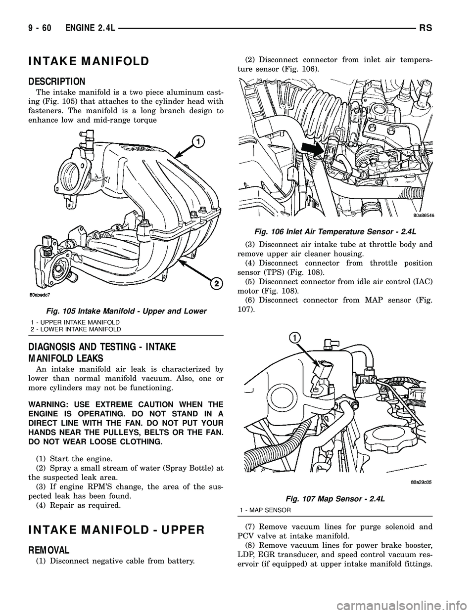
The intake manifold is a two piece aluminum cast-
ing (Fig. 105) that attaches to the cylinder head with
fasteners. The manifold is a long branch design to
enhance low and mid-range torque
DIAGNOSIS AND TESTING - INTAKE
MANIFOLD LEAKS
An intake manifold air leak is characterized by
lower than normal manifold vacuum. Also, one or
more cylinders may not be functioning.
WARNING: USE EXTREME CAUTION WHEN THE
ENGINE IS OPERATING. DO NOT STAND IN A
DIRECT LINE WITH THE FAN. DO NOT PUT YOUR
HANDS NEAR THE PULLEYS, BELTS OR THE FAN.
DO NOT WEAR LOOSE CLOTHING.
(1) Start the engine.
(2) Spray a small stream of water (Spray Bottle) at
the suspected leak area.
(3) If engine RPM'S change, the area of the sus-
pected leak has been found.
(4) Repair as required.
INTAKE MANIFOLD - UPPER
REMOVAL
(1) Disconnect negative cable from battery.(2) Disconnect connector from inlet air tempera-
ture sensor (Fig. 106).
(3) Disconnect air intake tube at throttle body and
remove upper air cleaner housing.
(4) Disconnect connector from throttle position
sensor (TPS) (Fig. 108).
(5) Disconnect connector from idle air control (IAC)
motor (Fig. 108).
(6) Disconnect connector from MAP sensor (Fig.
107).
(7) Remove vacuum lines for purge solenoid and
PCV valve at intake manifold.
(8) Remove vacuum lines for power brake booster,
LDP, EGR transducer, and speed control vacuum res-
ervoir (if equipped) at upper intake manifold fittings.
Fig. 105 Intake Manifold - Upper and Lower
1 - UPPER INTAKE MANIFOLD
2 - LOWER INTAKE MANIFOLD
Fig. 106 Inlet Air Temperature Sensor - 2.4L
Fig. 107 Map Sensor - 2.4L
1 - MAP SENSOR
9 - 60 ENGINE 2.4LRS